Table of Contents

Related Manuals for Omron ZW-S7010


Summary of Contents for Omron ZW-S7010
- Page 1 Troubleshooting 8-1 Error Messages ......... . 256 8-2 Troubleshooting .
-
Page 2: Error Messages
8-1 Error Messages For the displayed or output error messages in each communication, refer to the following manual. 6-1 Error Messages in Confocal Fiber Type Displacement Sensor User's Manual for Communication Settings (Z363). Error Messages ZW-7000/5000 User's Manual... - Page 3 − The fiber cable is disconnected. The Sensor Head and extension fiber cable need to be replaced or repaired. Please contact an OMRON branch or sales office. Display error The main display remains TIMING input is not ON.
- Page 4 Error type Phenomenon Cause Countermeasure Pages − Measurement [DARK] is displayed on Amount of the light is insufficient. Set the Exposure time to be long or error the main digital. reduce Noise Cut Level within the range of Noise Level. −...
- Page 5 The fiber cable is disconnected. The Sensor Head needs to be p.58 repaired. Please contact an OMRON branch or sales office. For Sensor Head repair, return as a set with the Calibration ROM. The logical beam does The LIGHT OFF input line is short- Check the wiring.
- Page 6 Error type Phenomenon Cause Countermeasure Pages − Communication RS-232C communication Cable wirings are wrong. Check the wiring to ensure proper error cannot be established. Cables are not connected correctly. connection. Communication settings are wrong. Set the same communication setting for both the Sensor Controller and the external devices.
- Page 7 APPENDICES 9-1 Specifications and External Dimensions ..... . 264 9-2 Firmware Update ......... 283...
-
Page 8: Specifications And External Dimensions
μ The measurement range is higher 28 s than measurement cycle. Capacity value when OMRON standard mirror surface target is measured at the measurement center distance as the average of 16,384 times μ When connected with the controller for the Export Control Trade Ordinance (ZW-7000T), the minimum resolution is 0.25 m, regardless of the Sensor head or setting condition. - Page 9 Accessories Calibration ROM fixing screws (M2), Fiber cable protective cap, Strap (1), Instruction Manual, Precautions Capacity value when OMRON standard mirror surface target is measured at the measurement center distance as the average of 16,384 times μ When connected with the controller for the Export Control Trade Ordinance (ZW-5000T), the minimum resolution is 0.25 m, regardless of the Sensor head or setting condition.
-
Page 10: External Dimensions
External Dimensions ● ZW-S7010/S7020/S7030 (Unit: mm) ● ZW-S5010/S5020/S5030 (Unit: mm) Specifications and External Dimensions ZW-7000/5000 User's Manual... - Page 11 ● Calibration ROM (Unit: mm) * This comes with the Sensor Head (ZW-S7010/S7020/S7030/S5010/S5020/S5030). Be sure to use a Calibration ROM together with the Sensor Head with the same serial number. ZW-7000/5000 Specifications and External Dimensions User's Manual...
-
Page 12: Spot Diameter
Spot diameter ● ZW-S7010/S5010 ● ZW-S7020/S5020 ● ZW-S7030/S5030 Specifications and External Dimensions ZW-7000/5000 User's Manual... -
Page 13: Sensor Controller
Sensor controller Specifications Item Specifications ZW-7000@ ZW-5000@ Input/output type NPN/PNP dual type Number of connected sensor heads Sensor head compatibility ZW-S70@@ ZW-S50@@ Light source for measurement White LED LED Safety Risk Group 3 (IEC62471) Segment Main display 11-segment white display, 6 digits Display Sub-display 11-segment green display, 6 digits... - Page 14 Item Specifications ZW-7000@ ZW-5000@ External I/F Ethernet 100BASE-TX/10BASE-T, Non-procedure (TCP/UDP), EtherNet/IP EtherCAT EtherCAT exclusive protocol 100BASE-TX RS-232C Max. 115,200 bps -10 V to +10 V, output impedance: 100 Ω Analog Analog voltage output output (OUT V) terminal 4 mA to 20 mA, max. load resistance: 300 Ω Analog current output block (OUT A)
- Page 15 Item Specifications ZW-7000@ ZW-5000@ Main functions Exposure time Automatic/Fixed 20 μs to 400 μs Measuring cycle 80 μs to 1600 μs Material setting Standard/Mirror/Rough surfaces Measurement item Height/Thickness of transparent object/Calculation Filtering Median/Average/Differentiation/High pass/Low pass/Band pass Output Scaling/Different holds/Zero reset/Logging for a measured value Display Measured value/Threshold value/Analog output voltage or current value/ Judgment result/Resolution/Light power/Internal logging condition...
-
Page 16: Status Indicators
Status indicators Mode Status Display Output Input RS-232C/ Ethernet 11-segment dis- ANALOG Judgment out- LIGHT OFF Zero play Output reset (HIGH/PASS/ LOW) Normal measurement Measurement Output Judgment Enabled Enabled Enabled result according to result measurement Non- KEEP Previous value result measurement CLAMP −... - Page 17 External Dimensions ● ZW-7000 (Unit: mm) ZW-7000/5000 Specifications and External Dimensions User's Manual...
-
Page 18: Ethercat Communications Specifications
● ZW-5000 (Unit : mm) SCREW HOLE FOR CONNECTING M2x0.4 DEPTH 2.0MAX SCREW CONNECTING FRAME GROUND TERMINAL M4 L6.0 SCREW CONNECTING FRAME GROUND TERMINAL M4 DEPTH 7.0MAX 139.5 SLIDER FOR MOUNTING DIN-RAIL 4-Dia.4.5 55±0.1 MOUNTING SCREW HOLES 4-M4 DEPTH 6.0MAX. MOUNTING HOLES EtherCAT communications specifications Item... -
Page 19: Pc Tools (Sysmac Studio)
PC tools (Sysmac Studio) (* ) Item Operating environment (*1) Operating system (OS) Windows 7 (32-bit/64-bit version) Japanese or English Windows 8 (32-bit/64-bit version) Windows 8.1 (32-bit/64-bit version) Windows 10 (32-bit/64-bit version) Windows computers with Intel® Celeron® processor 540 (1.8 GHz) or faster CPU. Intel®... -
Page 20: Extension Fiber Cable
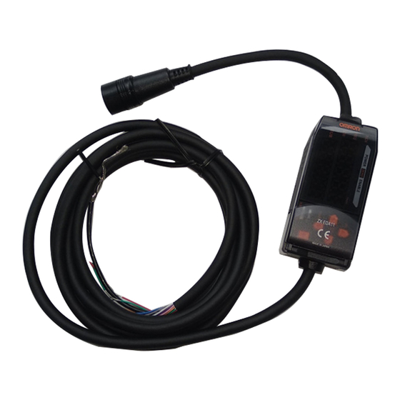
Accessories Extension fiber cable ● ZW-XF7002R/XF7005R/XF7010R/XF7020R/XF7030R Fiber cable (3.0 Dia.) Serial number label Name plate (Unit : mm) Fiber connector Fiber connector (Controller side) (Sensor head side) 2-0.7 Dia. 2-0.7 Dia. (25) (40) (30) (40) (25) 12-0.125 Dia. 12-0.125 Dia. (25.4) (60) * The following table lists cable lengths per models. - Page 21 ● ZW-XF5002R/XF5005R/XF50010R/XF5020R/XF5030R (Unit : mm) Name plate Fiber cable (3.0 Dia.) Fiber connector Serial number label Fiber connector (30) (57) (20) (60) (57) Connection adapter : ZW-XFC2 * The following table lists cable lengths per models. Type Specification L(mm) 11.9 Dia. 1.35 XF5002R 2000+200/0...
- Page 22 Connection adapter (for connecting fiber cable) ● ZW-XFCM (Unit: mm) The connection adapter (ZW-XFCM) comes packed together with the extension fiber cable (ZW-XF70 R), but the connection adapter alone can be purchased for maintenance. Extending fiber cable p.63. ● ZW-XFC2 (Unit: mm) 1.35 11.9Dia.
- Page 23 20 g Accessories Note on use EtherCAT cable Product name Manufacturer Cable length (m) Model Size/number of cores Cable with connector at OMRON XS5W-T421-AMD-K (number of pairs): AWG22 both ends (RJ45/RJ45) XS5W-T421-BMD-K × 2P XS5W-T421-CMD-K XS5W-T421-DMD-K XS5W-T421-GMD-K XS5W-T421-JMD-K Cable with connector at...
- Page 24 Kuramo Electric Co., LTD. KETH-PSB-OMR (number of pairs): AWG22 RJ45 assembled type OMRON XS6G-T421-1 × 2P connector This cable is available in 0.3, 0.5, 1, 2, 3, 5, 10, and 15 m lengths. For details, refer to the industrial Ethernet connector catalog (CDJC- 006).
- Page 25 RS-232C cable ● ZW-XPT2 (for PLC/programmable terminal connection) (Unit: mm) 2000±150 (100) (20±5) 33.6 25.4 11.7 9-pin square 17-pin square connector connector plug type Vinyl insulated round cord 5.8 Dia. 12 cores (Conductor cross sectional area: 0.08 mm /Insulated outside diameter: 0.6 Dia.) ●...
-
Page 26: Parallel Cable
Important Secure a minimum bending radius (R) for the cable that is at least as large as the specification value. If the bending radius is smaller than the specification value, this can cause damage to the cable. Parallel cable ● ZW-XCP2E (Unit: mm) +140 2110... -
Page 27: Firmware Update
Firmware Update For information on how to obtain the latest version of the firmware, please contact your OMRON sales representative. After obtaining the latest version of the firmware, follow the procedure below to update the firmware. Important Do not turn OFF the power supply to the Sensor Controller during updating. The Sensor Controller would no longer start up properly. -
Page 28: Performing The Update On Warp Engine Zw
Performing the Update on Warp Engine ZW-7 The most recent version of the software and PC Tool can be downloaded from the following website for OMRON members. Refer to the Member Registration Sheet that is enclosed with the Sensor. http://www.fa.omron.co.jp/zw Connect the the PC which is installed Warp Engine ZW-7 to ZW via Ethernet before operating. - Page 29 From the personal computer's Start menu, select [All Programs] - [OMRON] - [ZW] - [Warp Engine ZW-7]. The [Warp Engine ZW-7] screen is displayed. If Warp Engine ZW-7 fails to start up, a message and then the following screen is displayed.
- Page 30 In this case, contact an OMRON branch or sales office about the firmware version before the update and the one in the write file.
- Page 31 Index Median Filter Numeric 24 V input terminal block Terminal functions 30, 74 HIGH indicator Wiring Hold 30, 74 Clearing conditions 32-pole extension connector Signal functions Performing with Key Input Terminal functions Trigger Wiring Trigger Delay Analog output Icons Analog output terminal block Installation screw hole Terminal functions Wiring...
- Page 32 Installing on the DIN track Names of parts Precautions for installation Specifications Sensor Head Calibrate 35, 38, 66 External Dimensions Installation 25, 49 Interference Measuring range Names of parts Precautions for installation Specifications Spot diameter Setting Exposure Time Control Mode 119, 120, 121, 122 Setting Measurement Items Calculation...
- Page 33 ZW-7000/5000 Index User's Manual...
-
Page 34: Revision History
Revision History A manual revision code appears as a suffix to the catalog number at the bottom of the front and back covers of this manual. Cat. No. Z362-E1-05 Revision code Revision code Date Revision Contents April 2016 First edition. July 2016 Add the PDO synchronization mode and correct error sentences. - Page 36 OMRON ELETRÔNICA DO BRASIL LTDA • HEAD OFFICE São Paulo, SP, Brasil • 55.11.2101.6300 • www.omron.com.br OMRON EUROPE B.V. • Wegalaan 67-69, NL-2132 JD, Hoofddorp, The Netherlands. • +31 (0) 23 568 13 00 • www.industrial.omron.eu Authorized Distributor: Controllers & I/O •...