Table of Contents
Advertisement
Quick Links
Advertisement
Table of Contents

Related Manuals for Greenlee 639


Summary of Contents for Greenlee 639
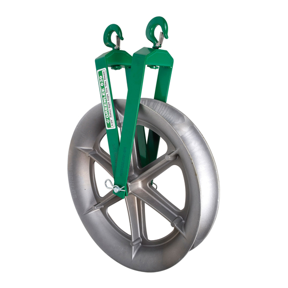
- Page 1 INSTRUCTION MANUAL Hook Sheaves 639, 650, 651, 652, and 653 8012, 8018, and 8024 Read and understand all of the instructions and safety information in this manual before operating or servicing this tool. Register this product at www.greenlee.com 52056646 REV 3 ©...
-
Page 2: Table Of Contents
Replacement manuals are available upon request at no charge at www.greenlee.com. All specifications are nominal and may change as design improvements occur. Greenlee Tools, Inc. shall not be liable for damages resulting from misapplication or misuse of its products. Tugger is a registered trademark of Tools, Inc. -
Page 3: Important Safety Information
Note: Keep all decals clean and legible, and replace when necessary. Wear eye protection when operating this tool. Failure to wear eye protection could result in serious eye injury from flying debris. Greenlee Tools, Inc. 4455 Boeing Dr. • Rockford, IL 61109-2988 USA • 815-397-7070... -
Page 4: Hook Load
30° 1.93 x T T = the tension exerted on the rope by the cable R = 2 x T puller Sheave Forces 0° 2 x T Greenlee Tools, Inc. 4455 Boeing Dr. • Rockford, IL 61109-2988 USA • 815-397-7070... -
Page 5: Some Hook Loads Illustrated
A rope that makes a 135° angle exerts 3/4 of the A rope that makes a 0° angle exerts 2 times the pulling force on the hook and structure. pulling force on the hook and structure. Greenlee Tools, Inc. 4455 Boeing Dr. • Rockford, IL 61109-2988 USA • 815-397-7070... -
Page 6: Calculating The Hook Load
T = the tension exerted on the rope by the cable puller Note: The total load on the support structure = R + the weight of the sheave. Greenlee Tools, Inc. 4455 Boeing Dr. • Rockford, IL 61109-2988 USA • 815-397-7070... - Page 7 Notes: The total load on the left support structure = R + the weight of the sheave. The total load on the right support structure = R + the weight of the sheave. Greenlee Tools, Inc. 4455 Boeing Dr. • Rockford, IL 61109-2988 USA • 815-397-7070...
-
Page 8: Hoist Hook
90 degrees, a bolt type anchor shackle or master link shall be used to attach the sling legs to the hook. 45° 45° Right Wrong Figure 3 Figure 4 Figure 5 Greenlee Tools, Inc. 4455 Boeing Dr. • Rockford, IL 61109-2988 USA • 815-397-7070... -
Page 9: Hook Latch Kit
6. Tighten self-locking nut on hook. latch clears point of hook. one end of bolt. Greenlee Tools, Inc. 4455 Boeing Dr. • Rockford, IL 61109-2988 USA • 815-397-7070... -
Page 10: Illustrations And Parts Lists
Hook Sheaves Illustration and Parts List— 639, 650, 651, 652, and 653 Maximum Pulling Force: 17.8 kN (4000 lb) 1/2" – 1-1/4" Use with Greenlee Easy Tugger and Tugger Cable Pullers ® ® Key Part No. Description Specifications A ..... 14.9 cm (5.88") -
Page 11: 8012, 8018, And 8024
Hook Sheaves Illustration and Parts List—8012, 8018, and 8024 Maximum Pulling Force: 35.6 kN (8000 lb) Use with Greenlee Easy Tugger , Tugger , Super Tugger , and Ultra Tugger Cable Pullers ® ® ® ® Key Part No. Description... - Page 12 4455 Boeing Drive • Rockford, IL 61109-2988 • USA • 815-397-7070 USA Tel: 800-435-0786 Canada Tel: 800-435-0786 International Tel: +1-815-397-7070 ©2019 Greenlee Tools, Inc. • An ISO 9001 Company Fax: 800-451-2632 Fax: 800-524-2853 Fax: +1-815-397-9247 www.greenlee.com...