Siemens SIMATIC ET 200eco PN M12-L Manual
Communication module
Hide thumbs
Also See for SIMATIC ET 200eco PN M12-L:
- Operating instructions manual (278 pages) ,
- Compact operating instructions (156 pages) ,
- System manual (127 pages)
Table of Contents
Advertisement
Quick Links
Advertisement
Table of Contents

Related Manuals for Siemens SIMATIC ET 200eco PN M12-L


Summary of Contents for Siemens SIMATIC ET 200eco PN M12-L
- Page 2 Preface ET 200eco PN M12-L Documentation Guide SIMATIC Product overview Wiring ET 200ecoPN Communication module CM 8x IO-Link + DI 4x24VDC M12-L Parameters/address space (6ES7148-6JG00-0BB0 Interrupts/diagnostics alarms Equipment Manual Technical specifications Dimension drawing 09/2020 A5E49284833-AA...
- Page 3 Note the following: WARNING Siemens products may only be used for the applications described in the catalog and in the relevant technical documentation. If products and components from other manufacturers are used, these must be recommended or approved by Siemens. Proper transport, storage, installation, assembly, commissioning, operation and maintenance are required to ensure that the products operate safely and without any problems.
-
Page 4: Preface
Preface Purpose of the documentation This equipment manual supplements the ET 200eco PN M12-L Distributed I/O System (https://support.industry.siemens.com/cs/ww/en/view/109778292) system manual. Functions that relate in general to the distributed I/O devices ET 200eco PN M12-L are described in this system manual. - Page 5 Siemens' products and solutions undergo continuous development to make them more secure. Siemens strongly recommends that product updates are applied as soon as they are available and that the latest product versions are used. Use of product versions that are no longer supported, and failure to apply the latest updates may increase customers' exposure to cyber threats.
-
Page 6: Table Of Contents
Table of contents Preface ..............................3 ET 200eco PN M12-L Documentation Guide ..................6 Product overview ..........................10 Properties .......................... 10 Operator controls and display elements ................13 Functions .......................... 14 Reset communication module to factory settings..............16 Wiring ..............................17 Terminal and block diagram .................... -
Page 7: Et 200Eco Pn M12-L Documentation Guide
This arrangement enables you to access the specific content you require. Basic information The system manual describes in detail the configuration, installation, wiring and commissioning of the SIMATIC ET 200eco PN M12-L distributed I/O system. The STEP 7 online help supports you in the configuration and programming. Device information... - Page 8 You must register once to use the full functionality of "mySupport". You can find "mySupport" on the Internet (https://support.industry.siemens.com/My/ww/en). Application examples The application examples support you with various tools and examples for solving your automation tasks.
- Page 9 You can find the SIMATIC Automation Tool on the Internet (https://support.industry.siemens.com/cs/ww/en/view/98161300). PRONETA SIEMENS PRONETA (PROFINET network analysis) allows you to analyze the plant network during commissioning. PRONETA features two core functions: • The topology overview automatically scans the PROFINET and all connected components.
- Page 10 ET 200eco PN M12-L Documentation Guide SINETPLAN SINETPLAN, the Siemens Network Planner, supports you in planning automation systems and networks based on PROFINET. The tool facilitates professional and predictive dimensioning of your PROFINET installation as early as in the planning stage. In addition, SINETPLAN supports you during network optimization and helps you to exploit network resources optimally and to plan reserves.
-
Page 11: Product Overview
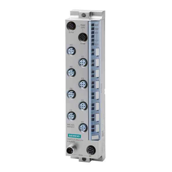
Product overview Properties Article number 6ES7148-6JG00-0BB0 View of the module Figure 2-1 View of the CM 8xIO-Link + DI 4x24VDC M12-L communication module Communication module CM 8x IO-Link + DI 4x24VDC M12-L (6ES7148-6JG00-0BB0 Equipment Manual, 09/2020, A5E49284833-AA... - Page 12 Product overview 2.1 Properties Properties The module has the following technical properties: • IO-Link master according to IO-Link specification V1.1 • 8 IO-Link ports usable as: – 4 IO-Link Ports Type Class A and 4 IO-Link Ports Type Class B •...
- Page 13 • M12 sealing cap See also You can find additional information on the accessories in the ET 200eco PN M12-L distributed I/O system (http://support.automation.siemens.com/WW/view/en/109774008) system manual. Communication module CM 8x IO-Link + DI 4x24VDC M12-L (6ES7148-6JG00-0BB0 Equipment Manual, 09/2020, A5E49284833-AA...
-
Page 14: Operator Controls And Display Elements
Product overview 2.2 Operator controls and display elements Operator controls and display elements The following figure shows the operator controls and display elements of the CM 8xIO-Link + DI 4x24VDC M12-L communication module. ① PN/MF (LAN): Sockets for connecting PROFINET ②... -
Page 15: Functions
Product overview 2.3 Functions Functions IO-Link is a point-to-point connection between an IO-Link master and an IO-Link device. On the IO-Link master, you can use IO-Link devices as well as conventional sensors/actuators with unshielded standard cables using proven 3-wire technology. IO-Link is downward- compatible to conventional digital sensors and actuators. - Page 16 You configure the IO-Link master with the Port Configuration Tool S7-PCT (PDCT) V3.5 SP2 or higher. Reference For more information on the IO-Link system, please see the IO-Link system (http://support.automation.siemens.com/WW/view/en/65949252) function manual. Communication module CM 8x IO-Link + DI 4x24VDC M12-L (6ES7148-6JG00-0BB0 Equipment Manual, 09/2020, A5E49284833-AA...
-
Page 17: Reset Communication Module To Factory Settings
• SIMATIC S7-PCT Factory Reset PROFINET factory reset You can find additional information on the PROFINET factory reset in the ET 200eco PN M12-L distributed I/O system (http://support.automation.siemens.com/WW/view/en/109774008) system manual. SIMATIC S7-PCT Factory Reset You trigger the reset to the factory settings in SIMATIC S7-PCT tool. -
Page 18: Wiring
Wiring Terminal and block diagram The following figure shows an example of the pin assignment for Port Class A and Port Class ① Bus interface with integrated 2-port switch Supply voltage 1L+ (non-switched) ② Electronics Ground 1M (non-switched) ③ Internal supply voltage Load voltage 2L+ (switched) ④... -
Page 19: Pin Assignment
Wiring 3.2 Pin assignment Figure 3-1 Terminal and block diagram Pin assignment Terminal assignment PROFINET connector The following table shows the pin assignment of the PROFINET connector. Table 3- 1 Pin assignment of the PROFINET connectors, port 1 and 2 Assignment of the core Assignment Front view of the connect-... - Page 20 Wiring 3.2 Pin assignment Pin assignment of the IO-Link sockets The table below shows the pin assignments of the 8 sockets for the connection of IO-Link. Table 3- 2 Pin assignment of the IO-Link sockets Assignment Front view of the sockets Port Class A Port Class B 24V encoder supply 1Us...
- Page 21 Wiring 3.2 Pin assignment Pin assignment of the connector for infeed of the supply voltage (M12 L-coded) The table below shows the pin assignment of the M12 L-coded connector for infeed of the supply voltage. Table 3- 3 Pin assignment of the supply voltage connector Assignment of the core Assignment Front view of the connector...
-
Page 22: Parameters/Address Space
Parameters/address space Parameters Parameters The following table shows the parameters that you can set for each port (each submodule) of the IO-Link master CM 8xIO-Link + DI 4x24VDC M12-L. Table 4- 1 Diagnostics and port parameters Parameters Value range Default Scope with configu- ration software, e.g. - Page 23 Parameters/address space 4.1 Parameters Parameters Value range Default Scope with configu- ration software, e.g. STEP 7 (TIA Portal) Inspection Level/Data Stor- Type-compatible Channel • Same type (V1.0) age* (V1.1) with Back- without Back- up&Restore up&Restore • Type compatible (V1.1) without Backup&Restore •...
-
Page 24: Explanation Of The Parameters
Parameters/address space 4.2 Explanation of the parameters Explanation of the parameters Diagnostics: Missing 2L+ Enable of the diagnostics for no or insufficient load voltage. Diagnostics: Undervoltage 1L+ Enabling of the diagnostics for insufficient supply voltage 1L+. Diagnostics port This parameter enables the diagnostics for the selected IO-Link port. In the diagnostics A distinction is made between error and maintenance interrupts. - Page 25 Set the IO-Link cycle time at the corresponding port. See also You can find out more about the vendor ID and the device ID of an IO-Link device on the Internet (https://support.industry.siemens.com/cs/ww/en/view/109748852). Communication module CM 8x IO-Link + DI 4x24VDC M12-L (6ES7148-6JG00-0BB0 Equipment Manual, 09/2020, A5E49284833-AA...
-
Page 26: Address Space
Parameters/address space 4.3 Address space Address space Introduction Der IO-Link master CM 8xIO-Link + DI 4x24VDC M12-L has eight ports. Each port is represented by a submodule. Configuration of the IO-Link ports of the IO-Link master CM 8xIO-Link + DI 4x24VDC M12-L The different operating modes of each IO-Link port are defined by configuring a corresponding submodule: •... - Page 27 * Bits are reset with function block "IO_LINK_MASTER_8" Figure 4-1 Structure of the PQI byte Reference For more information, please refer to the IO-Link system (http://support.automation.siemens.com/WW/view/en/65949252) function manual. Communication module CM 8x IO-Link + DI 4x24VDC M12-L (6ES7148-6JG00-0BB0 Equipment Manual, 09/2020, A5E49284833-AA...
-
Page 28: Interrupts/Diagnostics Alarms
Interrupts/diagnostics alarms Status and error displays LED displays The following figure shows the LED display of the CM 8xIO-Link + DI 4x24VDC M12-L communication module. ① RN/NS (RUN/network status) ② ER/MS (ERROR/module status) ③ MT/IO (MAINT/IO status) ④ PWR (POWER-LED) ⑤... - Page 29 Interrupts/diagnostics alarms 5.1 Status and error displays Meaning of the LEDs The following tables set out the meaning of the status and error displays. Behavior of the LEDs RN/NS (RUN/network status), ER/MS (ERROR/module status) and MT/IO (MAINT/IO status) Table 5- 1 Error display of the LED Meaning Remedy...
- Page 30 Interrupts/diagnostics alarms 5.1 Status and error displays Meaning Remedy RN/NS ERR/MS MT/IO (green) (red) (yellow) Not rele- Not rele- Maintenance Evaluate the maintenance vant vant events. On (yellow) The "Node flash test" is run- ning (the P1 LK and P2 LK flashes flashes flash...
- Page 31 Interrupts/diagnostics alarms 5.1 Status and error displays LEDs channel status DI Table 5- 4 Status displays of the DI0, DI1, DI2, and DI3 LEDs LEDs Meaning Channel status/channel error Process value = 0 Process value = 1 On (green) Channel status/channel error LEDs IO-Link The LEDs of IO-Link port class A and port class B have the same behavior.
-
Page 32: Interrupts
Interrupts/diagnostics alarms 5.2 Interrupts Interrupts Interrupts The IO-Link Master CM 8x IO-Link + DI 4x24VDC M12-L supports the following interrupts: • Diagnostics interrupts • Hardware interrupts (at submodule port) • Pull/plug interrupt (at submodule port) In case of an alarm, the CPU of the IO controller automatically calls the interrupt OBs. Information on the cause and class of the error is available, based on the OB number and start information. -
Page 33: Alarms
Interrupts/diagnostics alarms 5.3 Alarms Alarms The IO-Link master can generate diagnostic alarms of the type (severity) "Diagnostics" or "Maintenance" on behalf of the IO-Link device or the IO-Link port. • Alarms of the "Diagnostics" type indicate a malfunction of the IO-Link device / port and should be corrected immediately. - Page 34 Interrupts/diagnostics alarms 5.3 Alarms The IO-Link master generates channel diagnostics for each port. The port-specific channel diagnostics are shown in the port diagnostics (CET 0x9502 The following table gives you an overview of the possible diagnostic events and their meaning. Table 5- 6 Overview of error types IO-Link port diagnostics Error...
-
Page 35: Maintenance Events
Interrupts/diagnostics alarms 5.3 Alarms See also Diagnostics function manual (https://support.industry.siemens.com/cs/ww/en/view/59192926) 5.3.2 Maintenance events Maintenance events All IO-Link events of the type Warning generated by the IO-Link device or port are mapped to the PROFINET diagnostics alarm of the type "Maintenance" of the assigned submodule. The aim is the early detection and elimination of potential faults. -
Page 36: Technical Specifications
Technical specifications of the CM 8xIO-Link + DI 4x24VDC M12-L communication module The following table shows the technical specifications as of 09/2020. You can find a data sheet including daily updated technical specifications on the Internet (https://support.industry.siemens.com/cs/de/en/pv/6ES7148-6JG00-0BB0/td?dl=de). Article number 6ES7148-6JG00-0BB0... - Page 37 Technical specifications Article number 6ES7148-6JG00-0BB0 0.5 A; Per channel • Output current, max. Power loss Power loss, typ. 5.5 W Address area Address space per module 265 byte; + 8 bytes for QI information • Inputs 256 byte • Outputs Hardware configuration Submodules •...
- Page 38 Technical specifications Article number 6ES7148-6JG00-0BB0 Size of process data, output per module 256 byte Memory size for device parameter 2 kbyte; for each port Master backup possible with function block IO_LINK_MASTER_8 Configuration without S7-PCT Possible; autostart/manual function Cable length unshielded, max. 20 m Operating modes •...
- Page 39 Technical specifications Article number 6ES7148-6JG00-0BB0 Redundancy mode Media redundancy – Open IE communication • TCP/IP • SNMP • LLDP Interrupts/diagnostics/status information Alarms Yes; Parameterizable • Diagnostic alarm Yes; Parameterizable • Maintenance interrupt Diagnoses • Diagnostic information readable • Monitoring the supply voltage parameterizable –...
- Page 40 Technical specifications Article number 6ES7148-6JG00-0BB0 Ambient conditions Ambient temperature during operation -40 °C • min. 60 °C • max. Altitude during operation relating to sea level Up to max. 5 000 m, at installation height > 2 000 • Ambient air temperature-barometric pres- m additional restrictions, see manual for details sure-altitude Connection method...
-
Page 41: Dimension Drawing
Dimension drawing The following figure shows the dimension drawing of the CM 8xIO-Link + DI 4x24VDC M12-L communication module in front and side view. Figure A-1 Dimension drawing Communication module CM 8x IO-Link + DI 4x24VDC M12-L (6ES7148-6JG00-0BB0 Equipment Manual, 09/2020, A5E49284833-AA...