
Related Manuals for Agilent Technologies 11982A


Summary of Contents for Agilent Technologies 11982A
- Page 1 (217) 352-9330 | Click HERE Find the Keysight / Agilent 11982A at our website:...
- Page 2 Agilent 11982A Amplified Lightwave Converter Operation and Service Manual...
- Page 3 ❍ © Copyright material and workmanship for gies shall not be liable for any The OFF symbols Agilent Technologies 2000 a period of one year from date direct, indirect, special, inci- are used to mark the All Rights Reserved. Repro- of shipment.
- Page 4 To prevent electrical shock, do not remove covers. W A R N I N G To prevent electrical shock, disconnect the Agilent 11982A from mains before cleaning. Use a dry cloth or one slightly dampened with water to clean the external case parts. Do not attempt to clean internally.
- Page 5 Measurement accuracy—it’s up to you! Fiber-optic connectors are easily damaged when connected to dirty or damaged cables and accessories. The Agilent 11982A front-panel OPTICAL OUT connector is no excep- tion. When you use improper cleaning and handling techniques, you risk expensive instrument repairs, damaged cables, and compromised measurements.
-
Page 6: Table Of Contents
Connecting the Agilent 11982A to an Oscilloscope 3-2 Changing the Oscilloscope Display Units to Watts of Optical Power 3-4 4 Verification and Service Information Performing a Verification Check of the Agilent 11982A 4-2 Returning the Instrument for Service 4-4 Agilent Technologies Service Offices 4-7... -
Page 8: General Information
Description of the Agilent 11982A Lightwave Converter 1-2 Accessories 1-4 Agilent 11982A Specifications and Characteristics 1-5 Serial Numbers 1-8 Cleaning Connections for Accurate Measurements 1-9 Electrostatic Discharge Information 1-19 General Information... -
Page 9: Description Of The Agilent 11982A Lightwave Converter
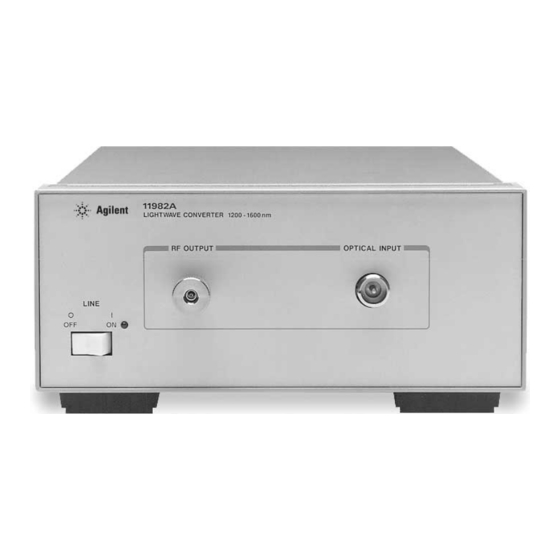
The Agilent 11982A covers the wavelengths from 1200 to 1600 nm with dc to 15 GHz (optical) modulating bandwidth. Its 300 volts/watt (nominal) conver- sion gain and 0.05% input optical reflections, significantly improves sensitivity for characterizing lightwave devices. - Page 10 Description of the Agilent 11982A Lightwave Converter Frequency-Domain Measurements with the Agilent 11982A Used with an electrical spectrum analyzer, the Agilent 11982A displays optical modulation power as a function of frequency. Intensity modulation, distortion, and laser intensity noise can also be displayed and measured. Using fre- quency-response corrections, you can predict and observe the effects of laser modulation on a system.
-
Page 11: Accessories
General Information Accessories Accessories Accessories Connector The Agilent 11982A has a variety of connector interfaces available. You must Interfaces specify one of the following connector interfaces when ordering your Agilent 11982A: • Diamond® HMS-10 Connector Interface (Option 011) • PC/FC Connector Interface (Option 012) •... -
Page 12: Agilent 11982A Specifications And Characteristics
General Information Agilent 11982A Specifications and Characteristics Agilent 11982A Specifications and Characteristics Table 1-1 lists specification, characteristics, typical performance, and nomi- nal values. The distinction between these terms is described as follows: • Specifications describe warranted performance over the temperature range 0°C to +55°C (unless otherwise noted). - Page 13 Plus or minus the connector variation. µ b. Equivalent to 3.7 W in a 15 GHz bandwidth. c. Corrections can be obtained from the lightwave personality ROM card or the Agilent 11982A Calibration Chart. d. Refers to electrical power units.
- Page 14 General Information Agilent 11982A Specifications and Characteristics Table 1-2. Agilent 11982A Specifications and Characteristics GENERAL SPECIFICATIONS Temperature Range Operating 0°C to +55°C Storage –40°C to +55°C EMI Compatibility Conducted and radiated emissions are in compliance with the requirements of FTZ 1046, CISPR Pub. 11 (1975), and MIL- STD-461C, Part 7, Methods CE03 and RE02.
-
Page 15: Serial Numbers
General Information Serial Numbers Serial Numbers Agilent Technologies makes frequent improvements to its products to enhance their performance, usability, or reliability, and to control costs. Agi- lent Technologies service personnel have access to complete records of design changes to each type of equipment, based on the equipment’s serial number. -
Page 16: Cleaning Connections For Accurate Measurements
Connectors also vary in the polish, curve, and concentricity of the core within the cladding. Mating one style of cable to another requires an adapter. Agilent Technologies offers adapters for most instruments to allow testing with many different cables. - Page 17 General Information Cleaning Connections for Accurate Measurements tions take repeatability uncertainty into account? • Will a connector degrade the return loss too much, or will a fusion splice be re- quired? For example, many DFB lasers cannot operate with reflections from connectors.
- Page 18 0.2 µm. This process, plus the keyed axis, allows very precise core-to-core alignments. This connector is found on most Agilent Technologies lightwave instruments. 1-11...
- Page 19 General Information Cleaning Connections for Accurate Measurements The soft core, while allowing precise centering, is also the chief liability of the connector. The soft material is easily damaged. Care must be taken to mini- mize excessive scratching and wear. While minor wear is not a problem if the glass face is not affected, scratches or grit can cause the glass fiber to move out of alignment.
- Page 20 General Information Cleaning Connections for Accurate Measurements Use the following guidelines to achieve the best possible performance when making measurements on a fiber-optic system: • Never use metal or sharp objects to clean a connector and never scrape the connector. •...
- Page 21 General Information Cleaning Connections for Accurate Measurements Figure 1-8. Damage from improper cleaning. While these often work well on first insertion, they are great dirt magnets. The oil or gel grabs and holds grit that is then ground into the end of the fiber. Also, some early gels were designed for use with the FC, non-contacting con- nectors, using small glass spheres.
- Page 22 General Information Cleaning Connections for Accurate Measurements • Keep connectors covered when not in use. • Use fusion splices on the more permanent critical nodes. Choose the best con- nector possible. Replace connecting cables regularly. Frequently measure the return loss of the connector to check for degradation, and clean every connec- tor, every time.
- Page 23 Cleaning Connectors The procedures in this section provide the proper steps for cleaning fiber- optic cables and Agilent Technologies universal adapters. The initial cleaning, using the alcohol as a solvent, gently removes any grit and oil. If a caked-on layer of material is still present, (this can happen if the beryllium-copper sides of the ferrule retainer get scraped and deposited on the end of the fiber during insertion of the cable), a second cleaning should be performed.
- Page 24 General Information Cleaning Connections for Accurate Measurements Table 1-4. Dust Caps Provided with Lightwave Instruments Item Agilent Part Number Laser shutter cap 08145-64521 FC/PC dust cap 08154-44102 Biconic dust cap 08154-44105 DIN dust cap 5040-9364 HMS10/dust cap 5040-9361 ST dust cap 5040-9366 To clean a non-lensed connector C A U T I O N...
- Page 25 To clean an adapter The fiber-optic input and output connectors on many Agilent Technologies instruments employ a universal adapter such as those shown in the following picture. These adapters allow you to connect the instrument to different types of fiber-optic cables.
-
Page 26: Electrostatic Discharge Information
General Information Electrostatic Discharge Information Electrostatic Discharge Information Electrostatic discharge (ESD) can damage or destroy electronic components. All work on electronic assemblies should be performed at a static-safe work station. Figure 1-10 shows an example of a static-safe work station using two types of ESD protection: •... - Page 27 General Information Electrostatic Discharge Information Figure 1-10. Example of a Static-Safe Work Station Reducing Damage Caused by ESD The following suggestions may help reduce ESD damage that occurs during testing and servicing operations. • Before connecting any coaxial cable to an analyzer connector for the first time each day, momentarily ground the center and outer conductors of the cable.
- Page 28 • Be sure that all instruments are properly earth-grounded to prevent build-up of static charge. Table 1-5 on page 1-21 lists static-safe accessories that can be obtained from Agilent Technologies by using the Agilent part numbers shown. Static-Safe Accessories Table 1-5. Static-Safe Accessories Agilent Part Number Description Set includes: 3M static control mat 0.6 m×...
-
Page 30: Installation And Preparation For Use
Preparing the Agilent 11982A for Use 2-2 Initial Inspection 2-2 Connecting the Agilent 11982A to a Power Source 2-4 Power Requirements 2-4 Setting the Line Voltage Selector 2-4 Checking the Fuse 2-5 Power Cable 2-6 Power Cords 2-7 Turning on the Agilent 11982A 2-9... -
Page 31: Preparing The Agilent 11982A For Use
Preparing the Agilent 11982A for Use Initial Inspection Inspect the Agilent 11982A shipping container for damage. If the shipping container or cushioning material is damaged, keep it until you have verified that the contents are complete and you have tested the lightwave converter mechanically and electrically. - Page 32 Item Description Agilent Part Number Outer Carton 9211-6485 Foam Pad Set 9220-4805 Table 2-2. Accessories Supplied with the Agilent 11982A (but not shown) Description Agilent Part Number Comments Adapter, SMA (f) to (f) 1250-1158 Shipped with the lightwave converter. Power cable Table 2-3 on page 2-4 Shipped with the lightwave converter.
-
Page 33: Connecting The Agilent 11982A To A Power Source
Power 75 VA (maximum) Setting the Line Voltage Selector Use the following procedure to set the Agilent 11982A’s voltage selector to the voltage range (100, 120, 220, or 240 V) corresponding to the available ac volt- age. C A U T I O N... -
Page 34: Checking The Fuse
Checking the Fuse The recommended fuse is a 0.5 A, 250 V, slow blow, Agilent Technologies part number 2110-0202. The line fuse is housed in a small container next to the voltage tumbler (see Figure 2-3 on page 2-6). -
Page 35: Power Cable
Installation and Preparation for Use Preparing the Agilent 11982A for Use Figure 2-3. Selecting the Line Voltage Value and Checking the Fuse Power Cable The lightwave converter is equipped with a three-wire power cable, in accor- dance with international safety standards. When connected to an appropriate power line outlet, this cable grounds the instrument cabinet. -
Page 36: Power Cords
79/200 Mint Gray Denmark 8120-2957 90° 79/200 Mint Gray * Part number shown for plug is the industry identifier for the plug only. Number shown for cable is the Agilent Technologies part number for the complete cable including the plug. - Page 37 Straight MITI 90/230 Dark Gray Japan 8120-4754 90° 90/230 * Part number shown for plug is the industry identifier for the plug only. Number shown for cable is the Agilent Technologies part number for the complete cable including the plug.
-
Page 38: Turning On The Agilent 11982A
The green light-emitting diode (LED) should light. If the LED should fail to light, see Chapter 4, “Verification and Service Information”. Figure 2-4. The Agilent 11982A Front Panel Table 2-4. Agilent 11982A Front-Panel Features Index Number Description Line Switch. -
Page 40: Time-Domain Measurements
Connecting the Agilent 11982A to an Oscilloscope 3-2 Changing the Oscilloscope Display Units to Watts of Optical Power 3-4 Time-Domain Measurements... -
Page 41: Connecting The Agilent 11982A To An Oscilloscope
Agilent 11982A to an ac power supply. 2 Connect an SMA or APC 3.5 mm adapter to the Agilent 11982A RF OUTPUT. Note The SMA female-to-female adapter that is shipped with the Agilent 11982A has been provided as a "connector saver."... - Page 42 Time-Domain Measurements Connecting the Agilent 11982A to an Oscilloscope Do not exceed the maximum input to the Agilent 11982A’s OPTICAL INPUT. The C A U T I O N maximum input power is shown on the front panel of the Agilent 11982A.
-
Page 43: Changing The Oscilloscope Display Units To Watts Of Optical Power
For the oscilloscope to display optical power, the voltage responsivity (also called the conversion gain) of the Agilent 11982A must be taken into account. The probe attenuation field is not available with some oscilloscopes. The oscilloscope display can still be con- verted to watts by dividing the oscilloscope’s reading (in volts) by the respon-... - Page 44 Table 3-1. The Agilent 11982A Calibration Chart Index Number Description Serial number of the Agilent 11982A. Calibration date of the Agilent 11982A. Frequency response of the Agilent 11982A in dB. The amplitude corrections at specific frequencies. Responsivity at 1300 nm and 1550 nm wavelengths.
-
Page 46: Verification And Service Information
Performing a Verification Check of the Agilent 11982A 4-2 If the Agilent 11982A verification check fails 4-3 Returning the Instrument for Service 4-4 Preparing the instrument for shipping 4-4 Agilent Technologies Service Offices 4-7 Service Information 4-8 General Information 4-8... -
Page 47: Performing A Verification Check Of The Agilent 11982A
1 Connect a laser with a wavelength of 1300 or 1550 nm (approximate) to an optical power meter, and measure the output power of the laser. 2 Connect the RF OUTPUT of the Agilent 11982A lightwave converter to a 50Ω load in parallel with a voltmeter (for example, an Agilent 3456A digital voltmeter). -
Page 48: If The Agilent 11982A Verification Check Fails
Performing a Verification Check of the Agilent 11982A If the Agilent 11982A verification check fails If the Agilent 11982A does not pass the verification check, you should recheck what was being done when the problem occurred. A few minutes spent per- forming some simple checks may save waiting for your instrument to be repaired. -
Page 49: Returning The Instrument For Service
Technologies Service Offices” on page 4-7 for a list of service offices. Agilent Technologies Instrument Support Center ... (800) 403-0801 If the instrument is still under warranty or is covered by an Agilent Technolo- gies maintenance contract, it will be repaired under the terms of the warranty or contract (the warranty is at the front of this manual). - Page 50 They may also cause instrument damage by generating static electricity. 3 Pack the instrument in the original shipping containers. Original materials are available through any Agilent Technologies office. Or, use the following guidelines: • Wrap the instrument in antistatic plastic to reduce the possibility of damage caused by electrostatic discharge.
- Page 51 Verification and Service Information Returning the Instrument for Service Sealed Air Corporation (Commerce, California 90001). Air Cap looks like a plastic sheet filled with air bubbles. Use the pink (antistatic) Air Cap™ to reduce static electricity. Wrapping the instrument several times in this ma- terial will protect the instrument and prevent it from moving in the carton.
-
Page 52: Agilent Technologies Service Offices
Verification and Service Information Agilent Technologies Service Offices Agilent Technologies Service Offices Before returning an instrument for service, call the Agilent Technologies Instrument Support Center at (800) 403-0801, visit the Test and Measurement Web Sites by Country page at http://www.tm.agilent.com/tmo/country/English/ index.html, or call one of the numbers listed below. -
Page 53: Service Information
Verification and Service Information Service Information Service Information This section describes how to service the Agilent 11982A. It contains the fol- lowing service information: • General Information. • Adjustment Procedure. • Troubleshooting. • Replacement Procedures. • Replaceable Parts. General Information... - Page 54 All work on electronic assemblies should be performed at a static-safe work Discharge station. See “Electrostatic Discharge Information” on page 1-19 for more infor- mation on preventing ESD. Required Service Table 4-1 on page 4-10 lists the tools that may be required to service the Tools Agilent 11982A.
-
Page 55: Adjustment Procedure
8710-1217 Adjustment Procedure The only adjustment for the Agilent 11982A is the +5.7 V dc voltage supply. To adjust the power supply, use an Agilent 3456A digital multimeter (or equiva- lent) to measure the dc output voltage at the power supply terminals. If the dc output voltage is not within tolerance, adjust the power supply. -
Page 56: Troubleshooting
3 If the voltage reading is not +5.7 V dc, adjust the +5V ADJ potentiometer (R12) for a reading of +5.7 V dc ±50 mV. Troubleshooting The main functional blocks of the Agilent 11982A are the power supply, the photodetector and the electrical amplifier unit. Figure 4-1. Agilent 11982A Block Diagram... -
Page 57: Replacement Procedures
The amplifier unit and the optical input connector cannot be replaced; if defective, the Agilent 11982A must be returned to Agilent Technologies for service. The –12 V and +12 V power supplies are not adjusted. The voltages on the... - Page 58 If a torque-measuring tool is not available, make semirigid cable connections finger-tight only. Do not overtighten! Note Replacing the RF cable or the RF connector may cause the Agilent 11982A to no longer meet the specifications and characteristics shown in Table 1-1 on page 1-6.
- Page 59 Verification and Service Information Service Information Figure 4-2. Wiring Diagram for the Line Module Table 4-4. Line Module to DC Power Supply Connections Cable Attachment Index Number Cable Color (from the Line Module) ac power harness White/brown/gray ac power harness Gray dc power supply (labeled 5) White...
- Page 60 Verification and Service Information Service Information Replacing the Unsolder the connections to the dc power supply. Remove the four screws Power Supply that attach the power supply to the chassis. Use Figure 4-3 Table 4-5 when installing a new power supply. Figure 4-3.
-
Page 61: Replaceable Parts
Verification and Service Information Service Information Replaceable Parts This section contains information for identifying and ordering replacement assemblies and mechanical parts for the Agilent 11982A lightwave converter. Replaceable Parts Table 4-6 on page 4-19 lists information for each major assembly and for each Table Format major mechanical and electrical part that is not part of a major assembly. - Page 62 Verification and Service Information Service Information Direct Mail-Order Within the USA, Agilent Technologies can supply parts through a direct mail- System order system. Advantages of using the system are as follows: • Direct ordering and shipment from Agilent Technologies. • No maximum or minimum on any mail order. (There is a minimum order amount for parts ordered through a local Agilent Technologies office when the orders require billing and invoicing.)
- Page 63 Verification and Service Information Service Information Figure 4-4. Agilent 11982A Assembly Level Replaceable Parts 4-18...
- Page 64 Verification and Service Information Service Information Table 4-6. Assembly-Level Replaceable Parts Index Agilent Part Number Description Number 5021-5814 REAR FRAME 08449-00002 PANEL, REAR 11982-00003 INSULATOR 11982-00004 DECK 5021-5830 SIDE STRUT 5086-7863 PHOTODETECTOR AND ELECTRICAL AMPLIFIER UNIT 08673-60040 RF CONNECTOR 11982-00001 FRONT PANEL, DRESS 1990-1238 LED, GREEN...
- Page 65 Verification and Service Information Service Information Figure 4-5. Agilent 11982A Replaceable Hardware Figure 4-6. Back of Front Frame 4-20...
- Page 66 Verification and Service Information Service Information Table 4-7. Replaceable Hardware Index Agilent Part Number Description Number 0515-1331 SCREW, MACH M4.0 X 6MM FLAT-HD 0515-0866 SCREW, MACH M3.0 X 8MM PAN-HD 0515-1090 SCREW, MACH M3.5 X 8MM PAN-HD 0515-0889 SCREW, MACH M3.5 X 6MM FLAT-HD 0380-0019 STANDOFFS (NUTS AND LOCK WASHERS ARE INCLUDED WITH THE...
- Page 68 1-9, 1-17 input non-lensed connectors, 1-17 connector, compressed dust remover, 1-16 voltage, connecting the Agilent 11982A to an oscillo- instrument, returning for service, scope, connector care, interfaces, light-emitting diode, cotton swabs, 1-16 lightwave converter, crowbar, overvoltage...
- Page 69 4-16 replacement procedures, 4-12 VA power requirements, replacing verification of the Agilent 11982A, the ac cable assembly, 4-13 verification test, failing, the line module, 4-13 voltage the power supply, 4-15 range, responsivity tumbler,...