
Related Manuals for Abit IP-95


Summary of Contents for Abit IP-95
- Page 1 IP-95 Motherboard Socket 775 Intel Core 2 Duo Intel Pentium D Intel Pentium 4 Intel Celeron D Intel Celeron VIA P4M890 / VT8237R Plus FSB1066 DDR2 533 or DDR 400 PCI Express 2x SATA 1.5Gb/s 5.1 Channel AC97 Audio...
- Page 2 No part of this manual may be reproduced, transmitted or transcribed without the expressed written permission of the manufacturer and authors of this manual. If you do not properly set the motherboard settings, causing the motherboard to malfunction or fail, we cannot guarantee any responsibility.
-
Page 3: Table Of Contents
1. Hardware Setup ... 1-1 1.1 Specifications ...1-1 1.2 Motherboard Layout...1-2 1.3 Choosing a Computer Chassis ...1-3 1.4 Installing Motherboard ...1-3 1.5 Checking Jumper Settings ...1-4 1.5.1 CMOS Memory Clearing Header and Backup Battery ...1-4 1.6 Connecting Chassis Components...1-6 1.6.1 ATX Power Connectors ...1-6 1.6.2 Front Panel Switches &... - Page 4 IP-95 IP-95...
-
Page 5: Hardware Setup
1. Hardware Setup 1.1 Specifications • LGA775 socket for Intel Core 2 Duo / Pentium D / Pentium 4 / Celeron D / Celeron processor with 1066MHz FSB • Supports Intel Hyper-Threading Technology Chipset • VIA P4M890 / VT8237R Plus Memory •... -
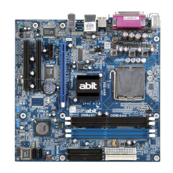
Page 6: Motherboard Layout
1.2 Motherboard Layout IP-95... -
Page 7: Choosing A Computer Chassis
Most chassis have alternatives for I/O shield located at the rear panel. Make sure the I/O shield of the chassis matches the I/O port configuration of this motherboard. You can find an I/O shield specifically designed for this motherboard in its package. -
Page 8: Checking Jumper Settings
1.5 Checking Jumper Settings • For a 2-pin jumper, plug the jumper cap on both pins will make it CLOSE (SHORT). Remove the jumper cap, or plug it on either pin (reserved for future use) will leave it at OPEN position. •... - Page 9 CMOS Backup Battery: An onboard battery saves the CMOS memory to keep the BIOS information stays on even after disconnected your system with power source. Nevertheless, this backup battery exhausts after some five years. Once the error message like “CMOS BATTERY HAS FAILED” or “CMOS checksum error”...
-
Page 10: Connecting Chassis Components
1.6 Connecting Chassis Components 1.6.1 ATX Power Connectors These connectors provide the connection from an ATX power supply. As the plugs from the power supply fit in only one orientation, find the correct one and push firmly down into these connectors. -
Page 11: Front Panel Switches & Indicators Headers
1.6.2 Front Panel Switches & Indicators Headers This header is used for connecting switches and LED indicators on the chassis front panel. Watch the power LED pin position and orientation. The mark “+” align to the pin in the figure below stands for positive polarity for the LED connection. -
Page 12: Fan Power Connectors
1.6.3 FAN Power Connectors These connectors each provide power to the cooling fans installed in your system. • CPU_FAN: CPU Fan Power Connector • SYS_FAN: System Fan Power Connector • PWR_FAN: Auxiliary Fan Power Connector ※ These fan connectors are not jumpers. DO NOT place jumper caps on these connectors. -
Page 13: Chassis Speaker Connector
1.6.4 Chassis Speaker Connector This header provides the connection to chassis speaker. IP-95... -
Page 14: Installing Hardware
1.7 Installing Hardware ※ DO NOT scratch the motherboard when installing hardware. An accidentally scratch of a tiny surface-mount component may seriously damage the motherboard. ※ In order to protect the contact pins, please pay attention to these notices: 1. A maximum 20 cycles of CPU installation is recommended. - Page 15 IP-95 8. Place the heatsink and fan assembly onto the socket. Align the four fasteners toward the four mounting holes on the motherboard. 9. Press each of the four fasteners down into the mounting holes. Rotate the fastener clock-wise to lock the heatsink and fan assembly into position.
-
Page 16: Ddr2/Ddr Memory Slots
1.7.2 DDR2/DDR Memory Slots This motherboard supports two DDR or two DDR2 DIMMs. Note that DDR & DDR2 cannot be both applied at the same time. Apply either DDR or DDR2 memory modules only! ※ Usually there is no hardware or BIOS setup required after adding or removing memory modules, but you will have to clear the CMOS memory first if any memory module related problem occurs. -
Page 17: Connecting Peripheral Devices
1.8 Connecting Peripheral Devices 1.8.1 Floppy and IDE Disk Drive Connectors The FDC1 connector connects up to two floppy drives with a 34-wire, 2-connector floppy cable. Connect the single end at the longer length of ribbon cable to the FDC1 on the board, the two connectors on the other end to the floppy disk drives connector. -
Page 18: Serial Ata Connectors
SATA device and connect the other end from the power supply. ※ The motherboard in this illustration is served for DEMO only, may not be the same type or model as the one described in this user’s manual. 1-14 IP-95... -
Page 19: Additional Usb 2.0 Port Headers
1.8.3 Additional USB 2.0 Port Headers Each header supports 2x additional USB 2.0 ports by connecting bracket or cable to the rear I/O panel or the front-mounted USB ports of your chassis. ※ Make sure the connecting cable bears the same pin assignment. 1.8.4 Internal Audio Connectors This connector connects to the audio output of internal CD-ROM drive or add-on card. -
Page 20: Front Panel Audio Connection Header
1.8.5 Front Panel Audio Connection Header This header provides the connection to audio connector at front panel. • To use the audio connector at front panel, remove all the jumpers on this header, and then connect to front panel by the extension cable provided with the chassis. •... -
Page 21: Pci And Pci Express X16, X1 Slots
1.8.6 PCI and PCI Express X16, X1 Slots Install PCI Express X16 graphics card into slot “PCIEX16”. Install PCI Express X1 card into slot “PCIEX1”. Install PCI cards into slots “PCI1” and/or “PCI2”. IP-95 1-17... -
Page 22: Connecting Rear Panel I/O Devices
1.9 Connecting Rear Panel I/O Devices The rear I/O part of this motherboard provides the following I/O ports: • Mouse: Connects to PS/2 mouse. • Keyboard: Connects to PS/2 keyboard. • LPT1: Connects to printer or other devices that support this communication protocol. -
Page 23: Bios Setup
2. BIOS Setup This motherboard provides a programmable EEPROM so that you can update the BIOS utility. The BIOS (Basic Input/Output System) is a program that deals with the basic level of communication between processor and peripherals. Use the BIOS Setup program only when installing motherboard, reconfiguring system, or prompted to “Run Setup”. - Page 24 IP-95...
-
Page 25: Driver & Utility
[Manual]: Click to enter the user’s manual menu. • [Utility]: Click to enter the utilities installation menu. • [ABIT Utility]: Click to enter the installation menu of utilities exclusively developed by ABIT. • Browse CD]: Click to browse the contents of this “Driver & Utility CD”. - Page 26 IP-95 IP-95...
-
Page 27: Multilingual Quick Installation Guide
4. Multilingual Quick Installation Guide 4.1 繁體中文 4.1.1 規格 處理器 • 1066MHz Core 2 Duo / Pentium D / Pentium 4 / Celeron D / Celeron • Intel Hyper-Threading 晶片組 • VIA P4M890 / VT8237R Plus 記憶體 • DDR2 533 DDR 400 •... -
Page 28: 快速安裝指南
• • • • • • • • • • • CMOS CMOS BIOS BIOS CMOS CMOS CMOS BIOS abit • [ATXPWR1] • [CPUFAN1] CPU • [SYSFAN1] • [AUXFAN1] • [NBFAN1] • [HLED] • [RST] • [SPKR] • [SLED] •... - Page 29 [FP-USB1] [FP-USB2] IEEE1394 [FP-1394-2] IEEE1394 IEEE1394 TPA0 + TPB0 + +12V [CD1] [AUX1] (Central Processing Unit, CPU) [CPUFAN1] IP-95 [FDC1] [FP-1394-1] TPA0 - TPB0 - +12V • Mouse • Keyboard • LPT1 • COM1 • OPT-IN1 S/PDIF • OPT-OUT1 S/PDIF AUDIO1: 7.1 •...
- Page 30 IP-95 IP-95...
-
Page 31: 简体中文
4.2 简体中文 4.2.1 规格 处理器 • 1066MHz 2 Duo / Pentium D / Pentium 4 / Celeron D / Celeron • Intel 芯片组 • VIA P4M890 / VT8237R Plus 内存 • DDR2 533 DDR 400 • 2 DIMM DDR 400 •... -
Page 32: 快速安装指南
4.2.2 快速安装指南 abit 硬件设置注意事项 • • • • • 将主板安装到底盘上 • • • • • • • • • CMOS 清除跳线 CMOS BIOS BIOS 正常 (默认) CMOS CMOS CMOS BIOS 连接底盘元件 ATX 电源:[ATXPWR1]、[ATX12V1] • [ATXPWR1] • 风扇连接器: [CPUFAN1]:CPU • [SYSFAN1]:... - Page 33 附加的 USB 端口接头:[FP-USB1]、[FP-USB2] 针脚 针脚定义 针脚 附 加 的 IEEE1394 端 口 接 头 : [FP-1394-1] 、 [FP-1394-2] IEEE1394 IEEE1394 针脚 针脚定义 针脚 TPA0 + TPB0 + +12V 内部音频连接器:[CD1]、[AUX1] CD-ROM 安装 CPU 和过热降温装置 (CPU) [CPUFAN1] 安装内存模块 静电可能会损坏计算机或板卡选件上的电子元件。在 开始上述操作之前,请触摸一下接地的金属物品,以 确保释放身上的静电。 IP-95 连接存储设备...
- Page 34 4-10 4-10 IP-95 IP-95...
-
Page 35: Appendix
5.1 Troubleshooting (How to Get Technical Support?) 5.1.1 Q & A Q: Do I need to clear the CMOS before I use a new motherboard to assemble my new computer system? A: Yes, we highly recommend that you clear the CMOS before installing a new motherboard. - Page 36 Motherboard: Type in the model name and revision number of your motherboard. Example: AA8XE REV: 1.00 • BIOS Version: Type in the BIOS version of your motherboard. (You can find it on the screen during the POST sequence.) • CPU: Type in the brand name and the speed (MHz) of your CPU. (Illustrate the over-clocking status if you had done so.)
- Page 37 See the next page for a blank Technical Support Form, or visit our website to fill in the form on line (http://www.abit.com.tw/page/en/contact/technical.php). Q. Is the motherboard dead? Do I need to return it to where I bought from or go through an RMA process? A: After you had gone through the troubleshooting procedures, yet the problem still exists, or you find an evident damage on the motherboard.
-
Page 38: Technical Support Form
5.1.2 Technical Support Form Region: E-mail: First name: Last Name: Subject: Motherboard: BIOS Version: CPU: Memory brand: Memory size: Memory configuration: Graphics card: Graphics driver version: Power supply maker: Power supply wattage: Storage devices: Optical devices: Other devices: Operating system:... -
Page 39: Contact Information
Wien, Austria Tel: 43-1-7346709 Fax: 43-1-7346713 Contact: office@abit-austria.at Website: http://www.abit-austria.at Shanghai Universal ABIT (Shanghai) Co. Ltd. FL 19 Xuhui Yuan BLOG NO.1089 ZhongShan s 2 RD, ShangHai 200030 The People's Republic of China Tel: (86-21) 54102211 Fax: (86-21) 54104791 Website: http://www.abit.com.cn Poland Universal ABIT Poland (Rep. - Page 40 P/N: 4310-0000-51 Rev. 1.00...