Table of Contents
Advertisement
Advertisement
Table of Contents

Related Manuals for Abit IL9 Pro


Summary of Contents for Abit IL9 Pro
- Page 1 IL9 Pro IL9 Pro-V Motherboard Intel Socket 775 Installation Guide...
- Page 2 If you do not properly set the motherboard settings, causing the motherboard to malfunction or fail, we cannot guarantee any responsibility. IL9 Pro/IL9 Pro-V...
-
Page 3: Table Of Contents
1.7.5 Front Panel Audio Connection Header ...11 1.7.6 PCI and PCI Express X16, X1 Slots ...12 1.8 Connecting Rear Panel I/O Devices... 12 IL9 Pro/IL9 Pro-V 2. BIOS Setup ... 13 3. Driver & Utility ... 14 4. Appendix ... 15 4.1 規格(繁體中文)...15... - Page 4 IL9 Pro/IL9 Pro-V...
-
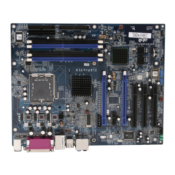
Page 5: Hardware Setup
1. Hardware Setup 1.1 Specifications • IL9 Pro: Support Intel Core 2 Duo, Pentium D, Pentium 4, Celeron D Processor with 1066MHz FSB • IL9 Pro-V: Support Intel Core 2 Duo, Pentium Dual-Core, Pentium D, Pentium 4, Celeron D Processor with 800MHz FSB •... -
Page 6: Choosing A Computer Chassis
Plug in the AC power cord only after you have carefully checked everything. To install this motherboard: 1. Locate all the screw holes on the motherboard and the chassis base. 2. Place all the studs or spacers needed on the chassis base and have them tightened. -
Page 7: Checking Jumper Settings
CPU or memory modules. This header uses a jumper cap to clear the CMOS memory and have it reconfigured to the default values stored in BIOS. IL9 Pro/IL9 Pro-V OPEN • Pins 2 and 3 shorted (Default): Normal operation. -
Page 8: Connecting Chassis Components
This connector supplies power to CPU. The system will not start without connecting power to this one. equivalent type Auxiliary 12V Power Connector: This connector provides an auxiliary power source for devices added on PCI Express slots. IL9 Pro/IL9 Pro-V... -
Page 9: Front Panel Switches And Indicators Headers
Definition HD LED + HD LED - RESET RESET Reserved IL9 Pro/IL9 Pro-V 1.5.3 FAN Power Connectors These connectors each provide power to the cooling fans installed in your system. • CPUFAN1: CPU Fan Power Connector •... -
Page 10: Installing Hardware
Aim at the socket and place the CPU package vertical down into the socket. 4. Visually inspect if the CPU is seated well into the socket. The alignment key must be located in the notch of package. IL9 Pro/IL9 Pro-V... - Page 11 7. Secure the lever with the hook under retention tab. IL9 Pro/IL9 Pro-V 8. Place the heatsink and fan assembly onto the socket. Align the four fasteners toward the four mounting holes on the motherboard.
-
Page 12: Ddr2 Memory Slots
1.6.2 DDR2 Memory Slots Both [DIMM2] and [DIMM4] slots appear in model IL9 Pro only. ※ To reach the performance of Dual Channel DDR2, the following rules must be obeyed: • For a 2-DIMM dual-channel installation: Populate DIMM modules of the same type and size on slots [DIMM1]+[DIMM3], or slots [DIMM2]+[DIMM4]. -
Page 13: Pci Express X16 Add-On Slots
Two PCIE graphics cards installation (CrossFire Mode): Install one CrossFire Edition graphics card into [Master] slot (the ™ PCIEX1 slot on this motherboard), and one CrossFire graphics card into [Slave] slot (the PCIEX2 slot on this motherboard). ™ The ATI CrossFire technology currently supports the ※... -
Page 14: Serial Ata Connectors
2. Attach the SATA power cable to the SATA device and connect the other end from the power supply. The motherboard in this photo is served for DEMO only, and ※ may not be the same type or model as the one described in this manual. -
Page 15: Internal Audio Connectors
1.7.4 Internal Audio Connectors This connector connects to the audio output of internal CD-ROM drive or add-on card. IL9 Pro/IL9 Pro-V 1.7.5 Front Panel Audio Connection Header This header provides the connection to audio connector at front panel. Signal Name... -
Page 16: Pci And Pci Express X16, X1 Slots
Install PCI cards into slots “PCI1”, “PCI2”, and/or “PCI3”. Slot PCI-E1 will be disabled when slot PCIEX2 is installed. ※ 1.8 Connecting Rear Panel I/O Devices The rear I/O part of this motherboard provides the following I/O ports: • Mouse: Connects to PS/2 mouse. •... -
Page 17: Bios Setup
2. BIOS Setup This motherboard provides a programmable EEPROM so that you can update the BIOS utility. The BIOS (Basic Input/Output System) is a program that deals with the basic level of communication between processor and peripherals. Use the BIOS Setup program only when installing motherboard, reconfiguring system, or prompted to “Run... -
Page 18: Driver & Utility
3. Driver & Utility The “Driver & Utility CD” that came packed with this motherboard contains drivers, utilities and software applications required for its basic and advanced features. Place the “Driver & Utility CD” into the CD-ROM drive in your system. -
Page 19: Appendix
晶片組 • IL9 Pro:Intel 945P / ICH7 • IL9 Pro-V:Intel 945PL / ICH7 記憶體 • IL9 Pro:4 條 (DIMM1~DIMM4) 240 針腳 DIMM 插槽支援最大 4GB 記憶體容量 支援雙通道 DDR2 667 無緩衝非 ECC 記憶體 • IL9 Pro-V:2 條(DIMM1 與 DIMM3)240 針腳 DIMM 插槽支援最... -
Page 20: 规格(简体中文
4.2 规格(简体中文) 处理器 • IL9 Pro: 支持具备 1066MHz 前端总线的 Intel Core 2 Duo, Pentium D, Pentium 4, Celeron D 处理器 • IL9 Pro-V: 支持具备 800MHz 前端总线的 Intel Core 2 Duo, Pentium Dual-Core, Pentium D, Pentium 4, Celeron D 处理器 • 支持 Intel 超线程技术... -
Page 21: Troubleshooting (How To Get Technical Support?)
4.3 Troubleshooting (How to Get Technical Support?) 4.3.1 Q & A Do I need to clear the CMOS before I use a new motherboard to assemble my new computer system? Yes, we highly recommend that you clear the CMOS before installing a new motherboard. -
Page 22: Technical Support Form
See the blank Technical Support Form, or visit our website to fill in the form on line (http://www.abit.com.tw/page/en/contact/technical.php). Is the motherboard dead? Do I need to return it to where I bought from or go through an RMA process? After you have gone through the troubleshooting procedures, yet the problem still exists, or you find an evident damage on the motherboard, please contact our RMA center. -
Page 23: Contact Information
Fax: 1-510-623-1092 Website: http://www.abit-usa.com Latin America: ventas@abit-usa.com RMA Center: http://rma.abit-usa.com UK, Ireland Universal ABIT UK Co. Ltd. Unit 3, 24-26 Boulton Road, Stevenage, Herts SG1 4QX, United Kingdom Tel: 44-1438-228888 Fax: 44-1438-226333 For technical support and RMA return: technical@abitcomputer.co.uk returns@abitcomputer.co.uk... - Page 24 P/N: 4310-0000-68 Rev. 2.00...