Table of Contents
Advertisement
Advertisement
Table of Contents

Related Manuals for CONCORD QV5200


Summary of Contents for CONCORD QV5200
- Page 1 Revised Manual DVRs...
- Page 2 Index Title Page Title Page Title Page Safety Precautions 4.3 Network Configuration 5.5.1 Information Chapter 1 Product Overview 4.4 Set Date & Time 5.5.2 Channel Information 1.1 What’s in the box? 4.5 Camera Configuration 5.5.3 Record Info 1.2 What’s what on the box? 4.6 Configure Storage 5.5.4 Network State Chapter 2 DVR Installation &...
- Page 3 Index Title Page Title Page Title Page 6.7 Motion Menu 7.3.1 Record Schedule 9.1.2 General – Port Configuration 6.7.1 Motion Detection Set-up 7.4 Capture Setup 9.2 DDNS 6.8 PIR Set-up 7.5 Motion & PIR Alarm Setup 9.3 Email 6.9 Intelligent Set-up 7.6 Exception Setup 9.3.1 Email Schedule Chapter 7 Record Setup...
- Page 4 Index Title Page Title Page 11.1.3 Output Configuration 11.5.3 Record Info 11.2 Multi-User 11.5.4 Network State 11.2.1 Changing Admin Password 11.2.2 Add New Users 11.2.3 New Users 11.3 Maintenance 11.3.1 Log 11.3.2 Load Default 11.3.3 System Upgrade 11.3.4 Parameter Management 11.3.5 Auto Reboot 11.4 IP Camera Maintain 11.5 IP Information...
-
Page 5: Safety Precautions
Safety Precautions Please carefully read the following safety precautions so as to avoid personal injuries and prevent the equipment and other connection devices from being damaged. 1. Power supply Never operate the equipment with any power supply other than the one supplied in the box. 2. -
Page 6: Chapter 1 Product Overview
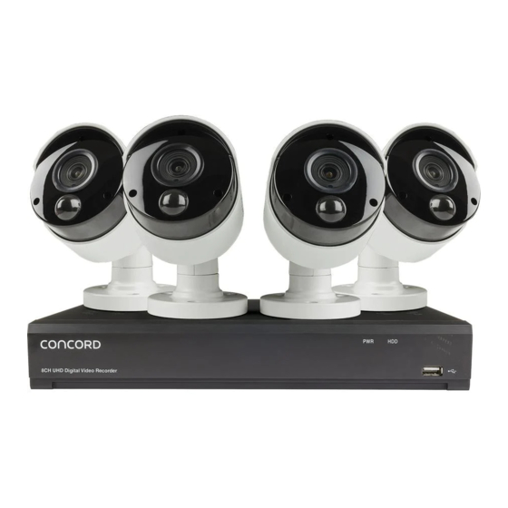
What’s in the box? 1.1 What’s in the box? Congratulations on your new Concord Professional Surveillance System. Inside the box you will find everything you need to connect your DVR and cameras to your TV or monitor. Cameras (4, 6 or 8) - Page 7 Chapter 1 Product Overview 1.2 What’s what on the box? Power Input Connect to the supplied mains power adaptor USB Port Connect the supplied mouse or external USB Hard Drive. Connect Connect to your TV or monitor, using either supplied Monitor HDMI or, if not available use the VGA Output (cable not supplied).
-
Page 8: Chapter 2 Dvr Installation & Connection
Chapter 2 DVR Installation & Connection 2.1 Connection Diagram Note: The above diagram is for reference purposes only, and uses a 4 channel DVR for the example. Your connections and setup may differ from this description. Any DVR with more than four cameras will come with an extra power supply. - Page 9 Chapter 2 DVR Installation & Connection 2.2 Power Supply Connection A mains power adaptor is included in the kit. Plug the adaptor into an available mains power outlet and the other end into the power socket on the back of the DVR.
-
Page 10: Chapter 3 Dvr Common Operations
Chapter 3 DVR Common Operations 3.1 Using the Supplied Mouse A USB Mouse is supplied to navigate the on-screen menus. Plug the mouse into an available USB port on the front or back of the DVR. 1. Left Button: Click to select menu options. During live viewing in split-screen view, double-click on a channel to view it in full-screen. -
Page 11: Using The Virtual Keyboard
Chapter 3 DVR Common Operations 3.2 Using the Virtual Keyboard A virtual keyboard will automatically appear on the screen when you need to enter data. Use the mouse to operate this keyboard. Backspace Shift key Enter Click shift key to display upper case letters and symbols Move Cursor... -
Page 12: Start Menu
Chapter 3 DVR Common Operations 3.3 Start Menu In this menu you can switch users, search videos, set up your DVR/NVR, manually lock the screen and shutdown, reboot or logout of the system. Whenever you want to make changes to the way your system operates you will need to use your password to unlock the screen. -
Page 13: Chapter 4 Dvr Setup
Chapter 4 DVR Setup 4.1 Before You Begin Before you begin setting up your DVR make sure: You complete the hardware installation. Your DVR/NVR is connected to a display. The DVR/NVR is connected to the Internet. Cameras are connected to the DVR/NVR and powered up. ATTENTION This initial Setup Guide is intended to provide a minimal effort guide to setting up a basic operational DVR system with default settings. - Page 14 Be sure to write down your login credentials in a secure place. If you forget your password you will not be able to access the DVR, and you will need to contact Concord customer support to reset the DVR password.
-
Page 15: Network Configuration
Chapter 4 DVR Setup 4.3 Network Configuration After setting up your password the next step is the Network Configuration Screen. There isn’t much you should need to do here but ensure the “DHCP” checkbox is ticked. The DVR/NVR automatically configures all other network parameters. Click the ‘Next”... -
Page 16: Set Date And Time
Chapter 4 DVR Setup 4.4 Set Date & Time This menu will set the system date and time, click the tabs to make adjustments. Date and Time: Set date, time, formats and time zone. NTP: You can also choose NTP (network time protocol) to automatically set the time using the network. -
Page 17: Camera Configuration
Chapter 4 DVR Setup 4.5 Camera Configuration This menu is for use when adding IP cameras through a router, it will not be necessary for most users so simply click Next. -
Page 18: Configure Storage
Chapter 4 DVR Setup 4.6 Configure Storage It is recommended to Format the HDD before first use – this will erase all stored data on the HDD. Auto Overwrite makes new data overwrite the old data as the HDD fills up. If you disable the Auto Overwrite feature, no new footage will be captured once the HDD is full. - Page 19 Chapter 4 DVR Setup 4.7 Configure Resolution Output Resolution drop down menu sets the image resolution displayed on the monitor or TV screen. This sets automatically when using the HDMI cable but can be adjusted manually if using the VGA option or if you intend to display a lot of channels on your screen.
- Page 20 Apple App Store ™ 2. When you first open the Concord Security App, you will see a blank screen, on the top right hand click on the ‘+’ symbol. 3. The smart phone camera will be activated, position your phone in front of the DVR screen over the QR code.
-
Page 21: Finish Set-Up
Chapter 4 DVR Setup 4.9 Finish Set-Up Review the settings and if you are happy with everything simply click the “Finish” button to save & exit the Wizard. -
Page 22: Chapter 5 Live View
Chapter 5 Live View... - Page 23 Chapter 5 Live View 5.0 Live View The Live View screen is the default display you will see when the DVR is on. You will be able to see each of the connected cameras and you can select the format in which they are displayed with either single images, scrolling single images or multiple images on the one screen.
- Page 24 Chapter 5 Live View 5.0 Live View If you click the icon above the recent events a menu will appear, you can then filter the recent events to only show a particular type or channel.
- Page 25 Chapter 5 Live View 5.1 Live View Iconography Channel Status Icon Check the status, date and time of your DVR with icons and text on the Live View screen DVR is recording on this channel. A PIR detection has been made on this channel.
-
Page 26: Camera Quick Toolbar
Chapter 5 Live View 5.2 Camera Quick Toolbar Manually record this channel. Click once to start and again to stop. Manually capture an image. Must be enabled in Capture Menu. Play back the last five minutes of recorded footage. Open PTZ control window. Zoom in on the image. - Page 27 Chapter 5 Live View 5.2 Camera Quick Toolbar When you click on the zoom icon channel that you have selected will expand to full screen and a small screen will appear in the bottom right hand corner showing the full channel image.
- Page 28 Chapter 5 Live View 5.3 Live View Task Bar Left Hand Side Open the Start Menu to access Shutdown, Unlock, Setup, Search and Admin. Four channel layout view. Select alternate channel layout views. Scrolls between full screen views of each channel. Play back latest recordings from each channel.
-
Page 29: Manual Record
Chapter 5 Live View 5.4 Manual Record When you click on the Manual Record icon the taskbar a menu will pop up that allows you to immediately begin recording on any of the channels by clicking on the slider next to the channel you wish to record. - Page 30 Chapter 5 Live View 5.5 System Information 5.5.1 Information When you click on the Information icon in the taskbar a window will pop up with a summary of your system settings and the versions you are running. This is a useful resource if you are upgrading cameras or if you have forgotten your password and need the MAC address to get us to reset your password.
-
Page 31: Channel Information
Chapter 5 Live View 5.5.2 Channel Information The next tab in the System Information window is Channel Information which gives you a summary of the settings for each channel including online status, resolution for each stream, frame rate set for each stream and the amount of bandwidth (Mbps) being used for each stream. -
Page 32: Record Info
Chapter 5 Live View 5.5.3 Record Info Under the Record Info tab you will find information on any channels that are currently recording. It will show you the whether or not the channel is recording under Record State, which stream it is recording at under Stream Type and the Resolution at which it is recording. -
Page 33: Network State
Chapter 5 Live View 5.5.4 Network State Under the Network State tab you will find a summary of the network settings for your system. You may need this information when connecting to your system through a network. -
Page 34: System Setup
System Setup When you click on the setup icon in the start menu, after you have entered your password you will be taken to this screen where you can select where you want to go in the System Setup Menu. Here you are able to configure the settings for Channel, Record, Alarm, Network, Device &... -
Page 35: Chapter 6 Channel Setup
Chapter 6 Channel Setup 6.1 General Controls When you are setting up your system there are a few processes that are common throughout that are worth remembering: 1. Wherever you see the Setup symbol means you are able to make further adjustments to this feature by clicking on the symbol. -
Page 36: Channel Menu
Chapter 6 Channel Setup 6.2 Channel Menu Under the top Channel Menu tab you can click on the lower Channel menu on the left of the screen and this will bring up three tabs to the right for: Analogue Channels IP Channels Protocol Management These tabs give you a summary of... - Page 37 Chapter 6 Channel Setup 6.2.1 Channel Live Menu The next menu on the left of the screen is the Live menu, in this menu you can adjust various parameters of the cameras. Each camera is identified by their channel number. In order to change settings for a camera click on the Setup icon.
- Page 38 You can change the camera protocol if you have a camera that you want to add to the network you can select from four different AHD formats, TVI and CVI, this is only necessary if you are adding a non-Concord camera.
- Page 39 Chapter 6 Channel Setup 6.3 Channel Image Control Menu This menu is only available for supported IP cameras. If you are using IP cameras refer to one of the Concord NVR manuals for details on how to use this menu.
- Page 40 Chapter 6 Channel Setup 6.4 Channel Pan-Tilt-Zoom (PTZ) Menu This menu is for setting up Pan-Tilt-Zoom cameras which are covered in a separate manual.
- Page 41 Chapter 6 Channel Setup 6.5 Video Capture Menus Before going on in this manual it is important to understand that Concord Digital Video Recorders are capable of recording and sending alerts of events in three different ways: Continuous recording – the camera records continuously until it fills up your Hard Disk Drive (HDD) storage and begins recording over the old videos from the beginning.
- Page 42 Chapter 6 Channel Setup 6.6 Video Cover Menu Video cover can be used to mask off areas that you don’t want recorded for privacy reasons, such as a children's play area or a neighbours yard who’s privacy you wish to respect or areas such as footpaths and streets to minimise false triggers from passing traffic.
-
Page 43: Motion Menu
Chapter 6 Channel Setup 6.7 Motion Menu This menu allows you to configure motion detection parameters for when your cameras are sensing motion only. When motion has been detected by one or more cameras, your DVR will begin recording and alert you to a potential threat by sending a push notification via the mobile app and/or sending you an email alert with an attached image from... -
Page 44: Motion Detection Setup
Chapter 6 Channel Setup 6.7.1 Motion Detection Set-up To minimize the number of events that are recorded and alerted you can filter out unwanted detections. You can do this by limiting the area of detection or reducing the sensitivity of the motion detection. The image covered in red squares is a live image from the camera you are editing, anything that moves in an area covered by a red square will trigger an event. - Page 45 All Concord cameras include PIR sensors at the front, these sensors detect the infrared radiation that is emitted from the surfaces in front of them. If an object moves through the area the sensor is detecting and the temperature of that object is different to the rest of the area, this will trigger an event.
-
Page 46: Pir Setup
Chapter 6 Channel Setup 6.8 PIR Setup As with the Motion Detection setup, you are able to adjust the sensitivity of the Thermal Detect so there is less chance that a smaller animal such as a cat or dog will trigger an event. Once you have finished your settings right click on the mouse and click apply in the main menu. - Page 47 Chapter 6 Channel Setup 6.8 PIR Setup The PIR setup menu uses a line drawing method to determine the area. Simply click on a point to start the shape of the Thermal Detect is active, drag the yellow line across to a point that will form a corner of the detection area, release the mouse button and then click and drag to the next point, repeat this process five times until you have drawn the shape you require to cover the area you wish to detect within.
-
Page 48: Chapter 7 Record Setup
Chapter 7 Record Setup In Channel Setup the aim was to fine tune your system so it was only recording events that you actually wanted to keep in the Record section of System Setup it is all about how you want to store your event recordings and how you can best use your space. This is all about the balance between high quality images and storage space;... -
Page 49: Stream Type
Chapter 7 Record Setup 7.1 Stream Type The first page you will see under the Record tab is the Encode page this is where you will make adjustments to the recording streams, recording resolution and how your recordings are encoded. In your system there are three streams that you can record to, this is done so that you can store different bit rates for different viewing devices. - Page 50 Chapter 7 Record Setup 7.2 Encode The purpose of the Encode menu is to fine tune the resolution, frame rate, compression and bitrate settings at which each channel (camera) records. It is very likely you will not need each channel to be recording at exactly the same resolution, frame rate and bitrate and reducing the settings of some of these elements can greatly assist you in reducing the amount of data that you store on your HDD or cloud storage.
- Page 51 Chapter 7 Record Setup 7.2.1 Encode Resolution One of the biggest contributors to how much data you use in a recording is the resolution at which you record it. You may find, especially if the camera is close to the subject such as a cash area in a store or monitoring a front door, that you don’t need all the resolution you have available to be able to see the detail you need.
- Page 52 Chapter 7 Record Setup 7.2.2 Encode FPS (Frames Per Second) Frame rate is the amount of individual images that are put together to make one second of video or frames per second (FPS). In CCTV cameras you can adjust the number of images that are used to make up a second of video, less images used equals less storage used. There is a trade off in video quality when reducing the frame rate, keeping in mind that 24fps is the standard for cinema so video around this frame rate will look natural, anything below about 15fps will start to look a little jerky and unnatural.
- Page 53 Chapter 7 Record Setup 7.2.3 Video Encode Type (H.264, H.265) Video compression is a means of encoding a digital video file in a way that reduces the size of the file by removing unnecessary or unimportant information. There are many types of video compression, however the two standards that have been adopted by most CCTV manufacturers are called H.264 and H.265.
- Page 54 Chapter 7 Record Setup 7.2.4 Encode Bitrate Control (Constant or Variable) One of the main contributors to the amount of bandwidth your system uses is the amount of movement and complexity of the image. The more that is going on in the image, the more storage is required. So a complex garden or interior scene is going to need a more data than a blank grey wall and a busy urban street is going to consume more space than a quiet driveway.
- Page 55 Chapter 7 Record Setup 7.2.4 Encode Bitrate Control (Constant or Variable) Variable Bit Rate (VBR): If the scene in front of the camera does not vary a lot over time then VBR is ideal and can save you a lot of bandwidth.
- Page 56 Chapter 7 Record Setup 7.2.5 Encode Bitrate Mode & Bitrate Different resolutions use different ranges of bitrate in order to display the best image possible, by default your recorder will select the highest bitrate for the resolution you are using. You can reduce this bitrate to reduce the amount of storage being used, just remember the higher the resolution the higher the bitrate needs to be, so if you drop a 4K camera down too far it will start to look very blurry, on the other hand if you put the bitrate up too high on a lower...
- Page 57 Chapter 7 Record Setup 7.2.5 Encode Bitrate Mode & Bitrate Resolution Good Bit Rate Better Bit Rate Best Bit Rate This table gives recommended bit rates based on the resolution to which 1280x720 1024 1280 1536 you have set the channel. It is intended as a guide to help you fine tune 2048 4096 5120...
-
Page 58: I Frame Interval
Chapter 7 Record Setup 7.2.6 I Frame Interval An I Frame is an image frame used in video compression as a reference image, typically every 20-30 frames. The compression compares the next frames after the I Frame for any changes and only sends those pixels that have changed. If you find h.264 or h.265 compression is reducing the quality too much you can try to fine tune this by increasing the number of I Frames that are used. - Page 59 Chapter 7 Record Setup 7.3 Record In this menu you can select the cameras you want recording, what their Stream Mode is and whether you want them to Pre-record. Record Enable can be deselected if you have a camera that you want to use for live view only. Your recorder will detect motion but it will not keep a recording, you will also not be able to use manual record.
-
Page 60: Record Schedule
Chapter 7 Record Setup 7.3.1 Record Schedule Using this function you can access and change the default recording schedule. The Record Schedule is shown as a 7 day grid divided into 48 half hour blocks for each day, you can select which camera you want to schedule by using the Channel drop down menu at the top. The various recording triggers are shown as color coded rings;... -
Page 61: Capture Setup
7.4 Capture Setup Your Concord recorder has the ability to capture still images of events which can be used to find motion events more quickly, to send to your email as an alarm or to take time lapse images of a scene. Maximum resolution for still image captures is 1080P HD. - Page 62 Chapter 7 Record Setup 7.5 Motion & PIR Alarm Setup You can set up your DVR to alert you to a potential threat at your home using the Alarm function to send an email to you and two other recipients, you can also use this function to upload pictures and videos using a file transfer protocol or to a cloud server and to trigger other cameras in your system to begin recording.
- Page 63 Chapter 7 Record Setup 7.5 Motion & PIR Alarm Setup Channel: Channel number being setup. Buzzer: Internal DVR audible buzzer will sound every time an alarm is triggered. Record: Switches recording on for other channels and gives you the option to nominate on which channels to begin recording. This increases the chances of capturing an identifying image of an intruder if you missed it on one camera, as another camera will already be recording if they come into its view.
- Page 64 Chapter 7 Record Setup 7.5 Motion & PIR Alarm Setup Record Channel: You can set you DVR to automatically begin recording on other channels if an alarm is triggered. This function is particularly useful if you have cameras that follow egress paths around your premises or cover blind spots of other cameras as you have a greater chance of capturing an identifying image of the intruder or their vehicle.
- Page 65 Chapter 7 Record Setup 7.6 Exception Setup Event Type: Your DVR can be set to alert you if it runs out of HDD space (No Space on Disk), there is an error on the HDD (Disk Error) or if one or more cameras have stopped sending a signal to the DVR (Video Loss).
-
Page 66: Chapter 8 Playback & Search
Chapter 8 Playback & Search The Search function gives you the ability to search for and play previously recorded videos as well as snapshots that are stored on your DVR’s hard drive. You have the choice of playing video that matches your recording schedule, manual recordings or motion events only. The Backup function gives you the ability to save important events (both video and snapshots) to a USB flash drive or USB Hard drive. - Page 67 Chapter 8 Playback & Search Video Playback Controls: to control the video playback. Enlarge the video playback to full screen Rewind, x2, x4, x8 and x16 Slow Play, 1/2, 1/4 and 1/8, 1/16 speed Play Pause Play frame by frame. Click once to play a frame of the video Stop Fast Forward, x2, x4, x8 and x16 Digital Zoom: Click to zoom in then click-and-drag on a camera image during playback to zoom in on the selected area.
- Page 68 Chapter 8 Playback & Search Timeline: Recordings are shown with coloured bars to represent different types of recording (legend shown in the bottom-right corner of the display). Use the timeframe options to view a smaller or larger time period. Different types of recording shown in different colours: Continuous recording Motion detection PIR detection...
- Page 69 Chapter 8 Playback & Search 8.2 Search & Play Video in the General Menu This menu gives you options to search & play recordings for a selected date. 1. Select a date to search for video recordings from the calendar. A red line on the date indicates there are recordings available.
-
Page 70: Video Clip Backup
Chapter 8 Playback & Search 8.2.1 Video Clip Backup 5. Move the mouse cursor to the timeline where you want to start the 1. Insert your external USB drive to the video clip. DVR. 2. Start a video recording playback. 3. - Page 71 Chapter 8 Playback & Search 7. When you have finished selecting the recordings you want to back up the Video Clip icon will change to the Save Video Clip icon , clicking on this icon will bring up the Backup Type window. Select a file type for your backup files, when you click the Save button the Backup window will open.
- Page 72 Chapter 8 Playback & Search 9. After clicking OK a progress bar will appear showing the 10. Once the files have been uploaded to your USB the progress number of files uploaded and the total progress. bar will be replaced by the message “Backup Successful”. You can now close the Backup window by clicking Cancel.
-
Page 73: Event Search, Playback & Backup
Chapter 8 Playback & Search 8.2.2 Event Search, Playback & Backup Event search lets you view a list of video recordings with the channel, start and end time, and recording type conveniently summarised. You can also quickly back up events to an external USB thumb drive or HDD. 1. - Page 74 Chapter 8 Playback & Search 6. Click the icons in the bottom-right corner of the menu to browse between pages of events, or input the page you want to browse. 7. You can switch the view of list form by clicking below the icons which are shown at the bottom right corner of the screen: Thumbnail view.
- Page 75 Chapter 8 Playback & Search Detailed view. In this view the Events will be listed lineally and include the date, start time, end time, file size and a playback button. In this view you can lock the video events to keep events from being overwritten in the hard drive.
- Page 76 Chapter 8 Playback & Search 8. When you click the left button of your mouse on one of the events, the system will show the Event Information on the left bottom corner of the screen. 9. In order to export your recorded videos to an external storage device such as a USB thumb drive, check the box next to the number of the event to select individual files, or check the box next to Select to select all events in the page.
-
Page 77: Sub-Periods Playback
Chapter 8 Playback & Search 8.2.3 Sub-periods Playback Sub-periods playback allows you to play multiple normal recordings and motion events simultaneously from a single channel. With normal and event recordings, the video is divided evenly depending on the split-screen mode that has been selected. For example, if the video is an hour long and you have selected Split-screens x 4, each split-screen will play for 15 minutes. - Page 78 Chapter 8 Playback & Search 7. Click the left button of your mouse upon a particular split-screen, the time period of the video split-screen will be displayed on the timeline. The color bar on the top of the timeline indicates the time span of the video split-screen you have clicked. The color bar on the bottom of the timeline indicates the time span for the whole videos you have searched.
- Page 79 Chapter 8 Playback & Search 8.3 Tag Search and View A simple of way of saving videos to view or download later is to use tags to identify these recordings. This is a handy tool if you have a lot of stored recordings but you are only interested in downloading videos that contain particular content.
- Page 80 Chapter 8 Playback & Search 8.3 Tag Search and View 4. If you choose to create a Customized Tag this window will pop up, if you click in the Tag Name box and the keyboard will appear to let give the Tag a name.
- Page 81 Chapter 8 Playback & Search 8.3 Tag Search and View 6. When you have finished typing the file name click on the Enter button and then click Save on the next window. Your Tag is now saved under the date and channel that appeared in the Add Tag window.
- Page 82 Chapter 8 Playback & Search 8.3 Tag Search and View 7. To view your tagged recordings first the Tag sub-menu in the Search menu. 1. Click Tag. 2. Select the date or date range you wish to search for Tags. 3.
- Page 83 Chapter 8 Playback & Search 8.3 Tag Search and View From here you can select the videos you wish to view by clicking Play at the bottom of the screen to play all videos in sequence or click the Playback button on the line containing the Tag you wish to view.
- Page 84 Chapter 8 Playback & Search 8.3 Tag Search and View From the Tag menu you have all the functions available in the General search menu including Zoom and Save to a USB device. The difference to the General Playback menu is in the Tag menu you will only see those videos you have tagged.
-
Page 85: Chapter 9 Network Setup
Chapter 9 Network Setup 9.1 General This menu allows you to configure network parameters, using DHCP or PPPoE. Your home network type is most likely DHCP, in this case simply ensure DHCP box is ticked and the system will set itself up. - Page 86 Chapter 9 Network Setup 9.1.1 General - PPPoE If your network is manually addressed you need to choose PPPoE and you will need your network authentication user name and password to the Internet.
- Page 87 Chapter 9 Network Setup 9.1.2 General – Port Configuration Web Port: This is the port that you will use to log in remotely to the DVR when using the Web Client. If the default port 80 is already taken by other applications, please change it.
- Page 88 Chapter 9 Network Setup 9.2 DDNS With current internet systems it is highly unlikely that you will need to use DDNS because we use a peer-to-peer technology, however there may be some unusual circumstances that will require the use of DDNS. DDNS provides a static address to simplify remote connection to your DVR and menu allows you to configure these settings.
- Page 89 Chapter 9 Network Setup 9.3 Email To use the email notification you need to set up your device with an email account to use when sending alerts, this can be any email address you currently use or you could use one you specifically set up for your recorder to use. If you wish to use the Cloud Storage function of your DVR you will need use the email address you use for your Dropbox or Google Drive accounts as these are the two cloud services that are recognised by your DVR.
- Page 90 Chapter 9 Network Setup 9.3 Email Email: Click “Enable” to input your email details and activate email alerts. Encryption: It is advisable to leave this on “Auto”. However in some circumstances it may be necessary if your email server requires the SSL or TLS verification to select one of these here.
- Page 91 Chapter 9 Network Setup 9.3 Email Password: Enter the password of your email. Click the “Show” checkbox if you would like to see your password. Sender: Input a name you would like displayed when the email arrives, such as “Home CCTV Alert”. Receiver1-3: Enter the email addresses to which you would like alerts sent.
- Page 92 Chapter 9 Network Setup 9.3 Email 10. Test Email: To make sure all settings are correct, click . The system sends an automated email message to your inbox. If you received the test email, it means the configuration parameters are correct. Click “OK” to continue. If you do not receive the test email, check your junk or spam folder.
-
Page 93: Email Schedule
Chapter 9 Network Setup 9.3.1 Email Schedule You need to configure the schedule to fully implement the email notification. The various email triggers are shown as color coded rings on the right hand side of the schedule; click inside the ring corresponding to the email trigger you want to use and then drag the cursor across the days and times you want to select, to deselect an area click or drag across on the cells or you want to remove in the same manner. - Page 94 Chapter 9 Network Setup 9.4 FTP Some customers may prefer to use an FTP client to upload their recordings, This menu allows you to enable FTP function to view and load captured snapshots from the DVR to your storage device over FTP. FTP Enable: Click to enable FTP function.
- Page 95 Chapter 9 Network Setup 9.4.1 FTP Schedule You need to configure the schedule to fully implement the FTP uploads. The various recording triggers are shown as color coded rings on the right hand side of the schedule; click inside the ring corresponding to the recording trigger you want to use and then drag the cursor across the days and times you want to select, to deselect an area click or drag across on the cells or you want to remove in the same manner.
-
Page 96: Chapter 10 Device Setup
Chapter 10 Device Setup In this menu you will find options that apply to your HDD and Cloud storage functions. 10.1 Disk If you click Format the HDD you will erase all stored data on the HDD, you want to do this to make sure you have a fresh start. - Page 97 Chapter 10 Device Setup 10.2 S.M.A.R.T. S.M.A.R.T. (Self-Monitoring, Analysis and Reporting Technology) is used to detect and report various indicators of HDD reliability, so you can save data to another source if the HDD is at risk of failure. You can also perform a test (there are three types available) to evaluate and detect potential drive errors. Self-check Type: There are three types available: Short: This test verifies major components of the hard drive such as read/write heads, electronics and...
- Page 98 Chapter 10 Device Setup 10.3 Cloud Your DVR can upload videos and image captures to either Dropbox or Google Drive which are both free services that allow you to easily store and share snapshots and always have them on hand when you need them. Because the free cloud space is fairly limited you should clear out your recordings fairly frequently as, depending on your recording...
- Page 99 Chapter 10 Device Setup 10.3 Cloud The cloud function on your DVR will only work with Dropbox or Google Drive so you need to have setup an account with one of these services before you can active the function on your DVR. The account must use the same email address and password used for the Email setup in your DVR (see 9.3 Email). Cloud Storage: Check to enable the function.
- Page 100 Chapter 10 Device Setup 10.3 Cloud Cloud Status: After you have successfully completed the cloud service activation process this box will changed to Activated. Capacity: The amount of capacity you have available in your cloud storage will be shown here. Video Type: This drop down menu allows you to specify what type of video you wish to save.
- Page 101 Chapter 10 Device Setup 10.3 Cloud Folder Name: Each channel will have its own folder within your cloud service, you can change the name of these folders by clicking on them and using the on screen keyboard to give them a name that is more relevant to you.
-
Page 102: Chapter 11 System
Chapter 11 System 11.1 System General Menu In this menu you change general system information such as date, time and region, edit passwords and permissions, and more. 11.1.1 General Device Name: In this field you can change the name of your DVR using the on-screen keyboard. -
Page 103: Date And Time
Chapter 11 System 11.1.2 Date and Time This menu will set the system date and time, click the tabs to make adjustments. Date and Time: Set date, time, formats and time zone. NTP: You can also choose NTP (network time protocol) to automatically set the time using the network. -
Page 104: Output Configuration
Chapter 11 System 11.1.3 Output Configuration This menu is used to create the default format for the Live View screen. Your DVR only has LIVE-OUT from the Video Output drop-down menu. SEQ Mode: The SEQ Mode is a mode available in the Live View where the feed from each camera is scrolled on the screen either as a single camera view or four or six cameras at a time. - Page 105 Chapter 11 System 11.1.3 Output Configuration Output Resolution: Select a display resolution that is suitable for your TV. 1920 x 1080 will suit most TVs. Scale and Offset: The DVR supports to adjust the size & position of the display screen to match your monitor or TV.
- Page 106 Chapter 11 System 11.1.3 Output Configuration Cursor Hidden Delay: Use this drop down menu to specify the amount of time the cursor is visible on the Live View screen when not in use, up to four minutes. Cursor Acceleration: This slider adjusts the speed at which the cursor moves relative to mouse movement. Transparency: This slider adjusts the transparency of the Menu Bar and Main Menu.
- Page 107 Chapter 11 System 11.2 Multi-User This menu allows you to configure the user name, password and user permission. The system supports two account types: • ADMIN — System Administrator: The administrator has full control of the system, and can change both administrator and user passwords and enable/disable password •...
-
Page 108: Changing Admin Password
Chapter 11 System 11.2.1 Changing Admin Password To change the password for the administrator or user accounts, click the User Edit icon . The password has to be a minimum of 8 characters and can contain a mixture of numbers and letters. Enter your new password again to confirm, and then click Save to save your new password. -
Page 109: Add New Users
Chapter 11 System 11.2.2 Add New Users 1. Select one of the user accounts that is currently disabled, click the User Edit icon 2. Select Enable from the drop-down next to User Enable. 3. Click the field next to User Name to change the user name for the account. -
Page 110: New Users
Chapter 11 System 11.2.3 New Users The administrator account is the only account that has full control of all system functions. You can enable or disable access to certain menus and functions of each user account using the User Permission menu. under the Permission tab 1. -
Page 111: Maintenance
Chapter 11 System 11.3 Maintenance In this section, you will be able to search & view the system log, load default settings, upgrade the system, export & import system parameters and manager system auto reboot. - Page 112 Chapter 11 System 11.3.1 Log The system log shows you important system events, such as motion alarms and system warnings. You can easily create a backup file of the system log for a set time period to a USB flash drive. Log Searching and Backing Up: 1.
-
Page 113: Load Default
Chapter 11 System 11.3.2 Load Default In this menu you can reset the DVR to its out-of-box settings. This can be helpful if your system is not operating the way it used to and you can’t work out which changes you have made have affected its behavior. -
Page 114: System Upgrade
Chapter 11 System 11.3.3 System Upgrade If our engineers come up with some major changes to the software that we believe all customers will benefit from you will able to upload this software directly to your DVR. If there is an upgrade available on the website simply download that to a clean USB storage device and connect that storage device to one of the USB ports on your DVR. -
Page 115: Parameter Management
Chapter 11 System 11.3.4 Parameter Management You can export the main menu settings you have configured to a USB flash drive, or import an exported setting file from a USB flash drive to the DVR. It is a good idea to do this prior to doing an upgrade or if you want to copy your settings to another DVR. -
Page 116: Auto Reboot
Chapter 11 System 11.3.5 Auto Reboot This menu allows the system to auto reboot the DVR regularly. It is recommended to leave this function enabled, as it maintains the operational integrity of your DVR. Auto Reboot: Check to enable. Time: You can set the DVR to reboot every day, week or month. -
Page 117: Ip Camera Maintain
Chapter 11 System 11.4 IP Camera Maintain This menu applies to systems that are using IP cameras through a network router and do not apply to standard DVR cameras using a BNC connector. If you would need information on maintaining IP cameras please use the NVR manual. - Page 118 Chapter 11 System 11.5 Information This menu allows you to view the system information, channel information, record information & network status. The most important part of this page is you will find the P2P ID & P2P QR code here. You can scan this QR cord with the mobile app to remotely view the DVR.
-
Page 119: Channel Info
Chapter 11 System 11.5.1 Channel Info View channel information for each connected camera such as alias, mainstream and substream recording specifications, motion detection status & privacy zone. - Page 120 Chapter 11 System 11.5.3 Record Info View recording information for each connected camera such as bitrate, stream type, recording resolution and frame rate (FPS). 11.5.4 Network State This page gives you a summary of the network settings for your DVR.