Carrier 40VM Series Installation And Operating Instructions Manual
Indoor fan coils vrf (variable refrigerant flow) system touch screen wired controller accessory
Hide thumbs
Also See for 40VM Series:
- Service manual (80 pages) ,
- Installation and operating instructions manual (12 pages) ,
- Installation and operating instructions manual (6 pages)
Table of Contents
Advertisement
Quick Links
Installation and Operating Instructions
CONTENTS
SAFETY CONSIDERATIONS . . . . . . . . . . . . . . . . . . . . . . . . .1
GENERAL . . . . . . . . . . . . . . . . . . . . . . . . . . . . . . . . . . . . . . . . .1
DIMENSIONAL DRAWING . . . . . . . . . . . . . . . . . . . . . . . . 3
INSTALLATION CONDIDERATIONS . . . . . . . . . . . . . . . . . 4
INSTALLATION . . . . . . . . . . . . . . . . . . . . . . . . . . . . . . . . . 4
• Wiring the controller . . . . . . . . . . . . . . . . . . . . . . . . . . . . . . 4
• Mounting the controller . . . . . . . . . . . . . . . . . . . . . . . . . . . . 4
OPERATION . . . . . . . . . . . . . . . . . . . . . . . . . . . . . . . . . . . . 5
• Turn the screen on . . . . . . . . . . . . . . . . . . . . . . . . . . . . . . .5
• ON/OFF setting . . . . . . . . . . . . . . . . . . . . . . . . . . . . . . . . . . . .5
• Setting the mode . . . . . . . . . . . . . . . . . . . . . . . . . . . . . . . . . . . 5
• Setting the fan speed . . . . . . . . . . . . . . . . . . . . . . . . . . . . . . . 5
• Setting the temperature . . . . . . . . . . . . . . . . . . . . . . . . . . . . . .5
MENU . . . . . . . . . . . . . . . . . . . . . . . . . . . . . . . . . . . . . . . . . 6
• Menu functions. . . . . . . . . . . . . . . . . . . . . . . . . . . . . . . . . . 6
• Menu operation. . . . . . . . . . . . . . . . . . . . . . . . . . . . . . . . . .6
• Setting louver . . . . . . . . . . . . . . . . . . . . . . . . . . . . . . . . . . . . . .6
• Enable schedule . . . . . . . . . . . . . . . . . . . . . . . . . . . . . . . . . . . .7
• Setting schedule. . . . . . . . . . . . . . . . . . . . . . . . . . . . . . . . . . . 7
• Holiday settings. . . . . . . . . . . . . . . . . . . . . . . . . . . . . . . . . . . . .7
• Setting override . . . . . . . . . . . . . . . . . . . . . . . . . . . . . . . . . . . 8
• Setting date and time . . . . . . . . . . . . . . . . . . . . . . . . . . . . . . . 8
• Setting daylight savings time . . . . . . . . . . . . . . . . . . . . . . . . . 8
• Indoor temperature display. . . . . . . . . . . . . . . . . . . . . . . . . . . 8
• Locking function. . . . . . . . . . . . . . . . . . . . . . . . . . . . . . . . . . 9
• Setting the touch tone. . . . . . . . . . . . . . . . . . . . . . . . . . . . . . 9
• Advanced information. . . . . . . . . . . . . . . . . . . . . . . . . . . . . . 9
• Querying indoor unit operating data . . . . . . . . . . . . . . . . . . .9
• Querying error records . . . . . . . . . . . . . . . . . . . . . . . . . . . . . 9
• Querying dry contact status . . . . . . . . . . . . . . . . . . . . . . . . .10
SERVICE MENU SETTINGS . . . . . . . . . . . . . . . . . . . . . . 10
• Service menu password. . . . . . . . . . . . . . . . . . . . . . . . . .10
• Setting room temp location. . . . . . . . . . . . . . . . . . . . . . . . . 10
• Room temp sensor offset . . . . . . . . . . . . . . . . . . . . . . . . . . .10
• Setpoint limit . . . . . . . . . . . . . . . . . . . . . . . . . . . . . . . . . . . . .10
• Thermal sensitivity adj . . . . . . . . . . . . . . . . . . . . . . . . . . . . . 11
• Changeover time. . . . . . . . . . . . . . . . . . . . . . . . . . . . . . . . . .11
• Anti cold blow. . . . . . . . . . . . . . . . . . . . . . . . . . . . . . . . . . . . 11
• Thermo off fan speed . . . . . . . . . . . . . . . . . . . . . . . . . . . . . 11
• Static pressure. . . . . . . . . . . . . . . . . . . . . . . . . . . . . . . . . . . 11
• Occupancy sensor. . . . . . . . . . . . . . . . . . . . . . . . . . . . . . . . 11
• Supplemental heat/aux heat status . . . . . . . . . . . . . . . . . . 12
• Setting the indoor unit address. . . . . . . . . . . . . . . . . . . . . . 12
• Brand choice setting . . . . . . . . . . . . . . . . . . . . . . . . . . . . . . 12
• Firmware update . . . . . . . . . . . . . . . . . . . . . . . . . . . . . . . . . 12
• Reset setting. . . . . . . . . . . . . . . . . . . . . . . . . . . . . . . . . . . . . .13
• Error codes. . . . . . . . . . . . . . . . . . . . . . . . . . . . . . . . . . . . . .14
SAFETY CONSIDERATIONS
Read and follow manufacturer instructions carefully.
Follow all local electrical codes during installation. All wiring
must conform to local and national electrical codes. Improper
wiring or installation may damage thermostat.
Understand the signal words - DANGER, WARNING,
and CAUTION. DANGER identifies the most serious hazards,
which will result in severe personal injury or death.
WARNING signifies hazards that could result in personal
injury or death. CAUTION is used to identify unsafe practices,
Manufacturer reserves the right to discontinue, or change at any time, specifications or designs without notice and without incurring obligations.
Catalog No. 20-40VM9005-01
Touch Screen Wired Controller Accessory
Part Number 40VM900005
Page
Form 40VM-4SI R1
Printed in U.S.A.
40VM Series Indoor Fan Coils
VRF (Variable Refrigerant Flow) System
which would result in minor personal injury or product and
property damage.
Recognize safety information. This is the safety-alert
symbol (
). When this symbol is displayed on the unit and in
instructions or manuals, be alert to the potential for personal
injury. Installing, starting up, and servicing equipment can be
hazardous due to system pressure, electrical components, and
equipment location.
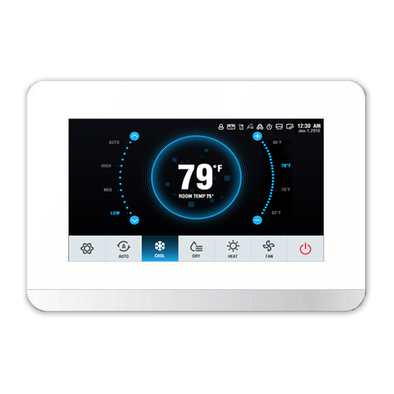
The VRF (variable refrigerant flow) touch screen wired
controller is a wall-mounted, low-voltage thermostat that
maintains room temperature by controlling system operation.
The controller is capable of displaying temperatures from
54ºF~86ºF for Standard Indoor Units, and 50ºF~86ºF for
Outside Air Units.
The touch screen wired controller accessory is available for
use with the VRF (variable refrigerant flow) system indoor
units (IDUs) listed in Table 2. Figure 1 and Table 3 show a
description of the icons used on this controller.
Table 1 - Components shipped with unit
NAME
IMAGE
Screws
Zip Tie
Table 2 -Wired Controller Accessory Usage
40VMA Outside Air
40VMC Compact Cassette
40VMF 4-Way Cassette
40VMH High Static Ducted
40VML Low Static Ducted
40VMM Medium Static
Ducted
40VMR Floor Console -
Recessed
40VMU Under Ceiling/Floor 012,018,024,030,036,048
40VMV Vertical AHU
40VMW High Wall
40VM900007 DI/DO Interface N/A
40VMZ Reheat Unit
Pg 1
GENERAL
QTY
FUNCTION
Used to Install Back Plate on
4
the Wall
1
Used to Bundle Wires
036, 048, 054, 072, 096
007,009,012,015
009,012,015,018,024,030,036, 048
024,030,036,048, 054, 072, 096
007, 009, 012, 015, 018, 024
007,009,012,015,018,024, 030,
036, 048
007, 009, 012, 015, 018, 024
018,024,030,036,048, 054
007,009,012,015,018, 024, 030
009,012,015,018, 024
08-20
Replaces: 40VM-4SI
Advertisement
Table of Contents

Related Manuals for Carrier 40VM Series


Summary of Contents for Carrier 40VM Series
-
Page 1: Table Of Contents
40VM Series Indoor Fan Coils VRF (Variable Refrigerant Flow) System Touch Screen Wired Controller Accessory Installation and Operating Instructions Part Number 40VM900005 CONTENTS which would result in minor personal injury or product and property damage. Page Recognize safety information. This is the safety-alert SAFETY CONSIDERATIONS . - Page 2 Table 3 — Icon Descriptions ICON DESCRIPTION 1. Screen ON/OFF icon Turns the Screen on/off 2. Room temperature Display current room temperature display 3. Scheduled time Displays next scheduled event 4. Menu icon Enters the menu 5. ON/OFF icon Powers the IDU on/off 6.
-
Page 3: Dimensional Drawing
DIMENSIONAL DRAWING Side View 1-1/8 Front View 4-7/8 7-1/4 Rear View 2-1/4 3-1/8 Note: All dimensions are shown in inches. Fig. 2 — Dimensions... -
Page 4: Installation Condiderations
INSTALLATION CONSIDERATIONS The thermostat should be mounted: • Approximately 48 in. from the floor • On a section of wall without water or drainage pipes The thermostat should NOT be mounted: • Where it can be directly affected by the unit’s discharge airflow •... -
Page 5: Operation
Setting the mode — 4. Angle the controller to insert it into the bottom snap joints Touch the “Mode” icon in the of the back cover as shown in Figure 7. mode selection area to choose the mode. WALL Insert Fig. -
Page 6: Menu
Touch the icon or the corresponding temperature text Menu operations — to set the temperature. See Figure 14. 1. Touch the “MENU” icon to open the menu. Fig. 14 — Setting the temperature Fig. 15 — Menu icon at home screen 2. -
Page 7: Enable Schedule
Enable schedule — Table 6 —Daily Patterns Adjust the wired controller clock before using schedule management. Parameter Description Select the specific day for timer 1. Choose Schedule on the menu interface. settings 2. Turn the Schedule ON/OFF. Set the timer time. Up to 8 timer time Time points can be set for each day 3. -
Page 8: Setting Override
2. Touch “By Date” or “By Day” to change how the Date is Setting daylight savings time — When enabled, displayed. See Figures 21 and 22. the clock automatically moves forward one hour at 2 am on the specified start date. The clock goes back one hour at 2 am on the specified end date. -
Page 9: Locking Function
Locking function Advanced information — Choose “Advanced Information” on the Menu interface. The wired controller can lock the following functions. They cannot be changed using the icons on the wired controller. Choosing “Lock” on the “Menu” interface will lock: • The IDU power-on/off function •... -
Page 10: Querying Dry Contact Status
Setting r oom temp location — Select “Room temp location” setting on the “Service” interface. Fig. 34 —Error Code/Address Field Querying dry contact status — 1. Choose “Dry contacts” on the “Advanced Information” interface to display status of unit and dry contact outputs. 2. -
Page 11: Thermal Sensitivity Adj
Thermal sensitivity adj — Thermo-off fan speed — Select “Thermal sensitivity Select “Thermo-off adj” setting on the “Service” interface. speed” setting on the “Service” interface. Fig. 43 —Thermo-Off Fan Speed Fig. 40 —Thermal Sensitivity Adj. This determines IDU fan behavior when the zone is The thermal sensitivity adj sets a capacity interval. -
Page 12: Supplemental Heat/Aux Heat Status
1. Choose “Brand choice setting” on the “Service” interface. Fig. 48 —Brand Choice Setting 2. Select either Carrier or Bryant. Fig. 46 —Supplemental Heat/Aux Heat Status These settings are used when the IDU is controlling a field- provided auxiliary heat source via its ACB interface contact output. -
Page 13: Reset Setting
5. Select the Firmware version. Reset setting — 1. Choose “Reset setting” on the “Service” interface. 2. Touch the “Reset icon” to reset. Fig. 51 —Firmware Selection 6. Touch the YES icon to confirm the update. Fig. 54 —Reset Settings 3. -
Page 14: Error Codes
ODU error (entered backup running mode) ODU error Water level alarm error © Carrier Corporation 2020 Manufacturer reserves the right to discontinue, or change at any time, specifications or designs without notice and without incurring obligations. Catalog No. 20-40VM9005-01 Form 40VM-4SI R1...