LG LWHD1006R Manual
Hide thumbs
Also See for LWHD1006R:
- Owner's manual (52 pages) ,
- Training manual (44 pages) ,
- Specification (2 pages)
Table of Contents
Advertisement
Advertisement
Table of Contents

Related Manuals for LG LWHD1006R


Summary of Contents for LG LWHD1006R
- Page 1 COMBO T RAINING Air Conditioner LWHD1006R LWHD1006R...
- Page 2 Some models may have four (4) letters instead of two (2) for the product code number. The third and fourth letters are significant only to the manufacturing facility. LWHD1006R...
-
Page 3: Specifications
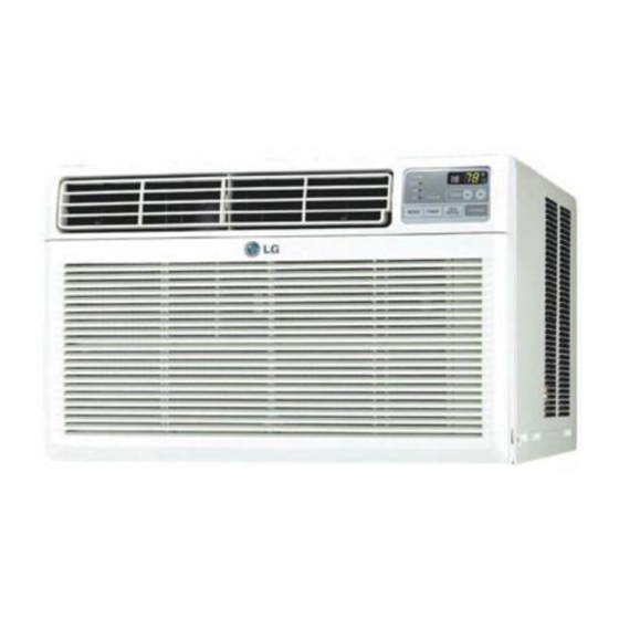
Specifications For temperature readings, DB = dry bulb and WB = wet bulb. There are types of thermometers used in conjunction with hygrometers in determining actual and absolute temperature and humidity readings. LWHD1006R... - Page 4 Introduction The LWHD1006R is a 115-volt window air conditioner. This product is a consumer comfort appliance, not a precision climate control system. LWHD1006R...
- Page 5 If the TEST button does not trip or the RESET button does not restore power, unplug the air conditioner and call an Authorized Service Technician. DO NOT tamper with or attempt to defeat or repair this device. A faulty socket or bad connection can cause this device to trip. LWHD1006R...
-
Page 6: Product Identification
Product Identification The model and serial numbers are on a sticker on the right side of the cabinet as you face the air conditioner inside the house. These are always visible if the air conditioner is installed correctly. LWHD1006R... - Page 7 Product Identification There is another sticker on the left side showing other important information about the air conditioner, including refrigerant type and charge. LWHD1006R...
-
Page 8: Maintenance
This slinger fan runs in the condensate collected in the pan and expels it through the condenser, which causes a slight increase in efficiency. There is no need to add water if the pan is dry. LWHD1006R... -
Page 9: Installation
15-amp circuit without using an extension cord. All applicable clearances should be maintained. All side louvers on the cabinet must remain exposed on the outside of the structure. LWHD1006R... - Page 10 Installation Abbreviated installation instructions are included in the event the installer must remove the air conditioner or replace it in the window. LWHD1006R...
- Page 11 •Install the air conditioner so the back (outside) is slightly lower than the front. This will force water to the drain at the back of the base pan. •Install the air conditioner so it is between 30 and 60 inches above the floor. LWHD1006R...
- Page 12 •If excess water collects in the base pan or the fan makes undesirable noise running in the water, remove the rubber plug and install the drain pipe. •You can connect a hose to the pipe and route the overflow to a convenient drain place. Drain plug (removed). LWHD1006R...
- Page 13 Installation •Plug the air conditioner into a single-outlet 15-amp circuit. •Be sure furniture and draperies do not block the air inlet and outlet. LWHD1006R...
- Page 14 Dimensions LWHD1006R...
- Page 15 Installation The installation kit includes all the parts necessary to install the air conditioner. The panels (1) are different for the left and right sides. Refer to the chart to identify parts . Kit is Part # 3127A10015B. LWHD1006R...
- Page 16 •Refer to the parts list to ensure all parts are included. •Sort the screws by size, shape, and quantity to determine which is which. •The foam strip (PE = poly-ethylene) with adhesive is to be applied under the upper guide before it is attached to the cabinet. LWHD1006R...
- Page 17 •Grip the base pan handle at the front and pull the chassis out while holding the cabinet. •Remove the packing material taped to the dryer inside the air conditioner and discard it. LWHD1006R...
- Page 18 Installation Attach the adhesive foam strip (11) to the bottom of the upper guide (10). LWHD1006R...
- Page 19 Attach the upper guide (10) to the cabinet using three screws (Type A). Note that the screws are inserted into the guide from inside the cabinet into the upper guide, not through the guide into the cabinet on the top. LWHD1006R...
- Page 20 Insert the frame guides in the bottom of the cabinet. Place the rounded part in the center track and the tabs into the rectangular slots. Press the clip down toward the front of the cabinet until the tabs click into place. LWHD1006R...
- Page 21 Installation Insert the frame curtains into upper and lower guides, then attach them with 4 screws (Type A) on each side. A long driver works best. LWHD1006R...
- Page 22 Place the cabinet in the window and align it with the centerline. Attach the cabinet to the sill with wood screws (Type B). Lower the window to allow the sash to fall behind the upper guide so the cabinet can rest against it. LWHD1006R...
- Page 23 Thread the nut onto the bolt and thread the bolt into the sill support. (Do this for both sides.) Use this bolt to adjust the cabinet height so it hangs out of the window with the back (outside) slightly lower than the front (inside). LWHD1006R...
- Page 24 Installation Use 2 screws to attach the sill support to the bottom of the cabinet from the inside. You may have to slide it forward or back to get it in the correct place. LWHD1006R...
- Page 25 Installation Attach the cabinet to the window sill by driving 3 Type B screws through the front angle of the cabinet into the window sill. LWHD1006R...
- Page 26 Installation Attach the frame curtains to the window sash (top) and track (bottom) using Type C screws. LWHD1006R...
- Page 27 Installation Slide the chassis into the cabinet. Reinstall the Type A screws in the sides and back of the cabinet. Place the foam strip in the gap between the inner and outer windows to keep drafts and vermin out. LWHD1006R...
- Page 28 Installation Attach the window locking bracket using a Type C screw. This secures the window to keep the air conditioner from falling out and burglars from getting in. LWHD1006R...
- Page 29 Installation Attach the front grille by placing the top on the cabinet and engaging the tabs on the grille in the slots on the cabinet. Push the grille down until it snaps into place. LWHD1006R...
- Page 30 Installation Open the front panel and attach the grille to the chassis using a Type A screw. LWHD1006R...
- Page 31 Features •Dehumidifier function - Unit operates at Low speed ONLY •Powerful and quiet •Slide-in chassis •Top cool air discharge •Low air intake •Built-in adjustable thermistor •Washable, reusable filter •Compact size •Rotary Compressor •Remote Control LWHD1006R...
- Page 32 Controls 1 POWER BUTTON 2 TEMPERATURE CONTROL 3 OPERATION MODE Cycles between these settings: COOL / ENERGY SAVER / FAN / DRY 4 FAN SPEED SELECTOR LOW, MEDIUM, and HIGH 5 TIMER 6 REMOTE CONTROL SENSOR LWHD1006R...
- Page 33 This air conditioner is designed for window installation and cooling and/or dehumidifying. There is no heat function. 1 POWER BUTTON 2 TEMPERATURE CONTROL 3 OPERATION MODE Cycles between these settings: COOL / ENERGY SAVER / FAN / DRY 4 FAN SPEED SELECTOR LOW, MEDIUM, and HIGH 5 TIMER LWHD1006R...
- Page 34 When Needed – Both Main & Display Boards should be replaced Part # 4994A10029A – Complete Wiring...
- Page 35 When Replacing Display & Main Boards Carefully Remove & Insert Ribbon Complete Wiring Part # 4994A10029A LWHD1006R...
- Page 36 Run Capacitor & 6 ±5% MFD 270 Volts (Hermetric) (Fan)
- Page 37 Checking a Run Capacitor • If unit is operating Measure VOLTAGE across Cap Terminals (Com to Hermetric) Measure AMPS (Start winding) 2650 X 3.7 ÷ 195.8= 50.07 MFD 2650 X Amps ÷ Volts = MFD LWHD1006R...
- Page 38 Checking a Run Capacitor 2650 x Amps ÷ Volts = MFD 2650 X 3. ÷194 = 41 MFD LWHD1006R...
- Page 39 2650 X Amps÷Volts= MFD 2650 X 2.32÷122.4= 50.2 Capacitor NOT in Circuit - Hermetric (50mfd) LWHD1006R...
- Page 40 2650 X 2.29÷122.6= 49.5 Capacitor NOT in Circuit 50mfd LWHD1006R...
- Page 41 FAN(6 mfd) 2650 x 0.26 ÷ 122.9= 5.6 Capacitor NOT in Circuit LWHD1006R...
- Page 42 Tubes are inserted approx. 1-2” LWHD1006R...
- Page 43 When Replacing an EVAP – All 8 Lines must be Removed LWHD1006R...
- Page 44 Condenser Inlet Tubes...
- Page 45 OPERATIVE – Green Indicator is lit...
- Page 46 Operative: Green Indicator is Lit...
- Page 47 Inoperative: Display is NOT Lit...
-
Page 48: Front Grille
2. Remove the screw that fastens the grille (bottom center). 3. Pull out on the right side and lift the grille upward off the hooks along the top of the cabinet. 4. Replacement is the reverse of these steps. LWHD1006R... - Page 49 CABINET 1. After removing the front grille, remove four screws, one on each side of the cabinet and two in the back. 2. Pull the chassis forward out of the cabinet. 3. Replacement is the reverse of these steps. LWHD1006R...
-
Page 50: Control Box
3. Remove the 2 screws that fasten the power cord. 4. Disconnect the ground screw from the base pan. 5. Remove the screw that secures the control box cover. 6. Remove the connector between the PCB and the motor lead. LWHD1006R... - Page 51 8. Remove the leads from the OLP. (Overload Protector) 9. Discharge the capacitor by shorting it with a 20kΩ resistor. 10.Lift the control box out of the way. 11.Reinstallation is the reverse of these steps. 12.Refer to the wiring diagram on page XX of the training manual. LWHD1006R...
- Page 52 AIR GUIDE and TURBO FAN (inside fan) 1. Remove the front grille. 2. Remove the cabinet. 3. Remove the control box. 4. Remove the 4 screws that secure the brace and lift it away. 5. Remove the 2 screws to remove the upper air guide. LWHD1006R...
- Page 53 Disassembly AIR GUIDE and TURBO FAN (inside fan) 6. Remove 2 screws that secure the evaporator. 7. Lift the evaporator slightly and fold it forward, as shown. 8. Press the plastic tabs to remove the plastic orifice (fan guide). LWHD1006R...
- Page 54 Slide the fan off the shaft. 10. Remove 2 screws that secure the lower air guide to the base pan. 11. Carefully push the lower air guide backward and pull it out of the base pan. 12. Replacement is the reverse of these steps. LWHD1006R...
- Page 55 4. Lift the condenser slightly and fold it to the left. 5. Use pliers to remove the clamp on the fan shaft. 6. Slide the fan off the shaft. 7. Replacement is the reverse of these steps. LWHD1006R...
- Page 56 Disassembly SHROUD (condenser) 1. Remove the fan, as described in the previous section. 2. Lift the shroud out of the base pan. 3. Replacement is the reverse of these steps. LWHD1006R...
-
Page 57: Overload Protector (Olp)
Disassembly OVERLOAD PROTECTOR (OLP) 1. Remove the cabinet. 2. Remove the nut and terminal cover. 3. Remove all leads from the overload protector (OLP). 4. Remove the overload protector. 5. Replacement is the reverse of these steps. LWHD1006R... - Page 58 Remove the overload protector. After recovering the refrigerant and purging the system, un- braze the suction and discharge tubes at the compressor. Remove the 3 nuts and washers that secure the compressor. Replacement is the reverse of these steps. LWHD1006R...
- Page 59 Disassembly CAPACITOR 1. Remove the screw and open the top cover of the control box. 2. Discharge the capacitor by shorting it with a 20KΩ resistor. 3. Disconnect the leads. 4. Replacement is the reverse of these steps. LWHD1006R...
-
Page 60: Power Cord
2. Disconnect the front panel from the control box by prying the tab open and folding it to the left. 3. Discharge the capacitor 4. Disconnect the leads from the capacitor and relay. LWHD1006R... - Page 61 7. If the cord is damaged or compromised in any way, it must be replaced with an exact replacement part, including any protective devices, rather than by a generic cord. 8. Use only a single point ground connection for ALL ground wires. LWHD1006R...
- Page 62 1. Remove the cabinet. 2. Remove the turbo (indoor) fan. 3. Remove the slinger (outdoor) fan. 4. Remove 4 screws that secure the fan motor to the air guide. 5. Lift the motor out. 6. Replacement is the reverse of these steps. LWHD1006R...
-
Page 63: Refrigeration Cycle
1. Remove 5 screws that secure the secure the brace. 2. Remove the 5 screws that secure the condenser shroud. 3. Discharge and recover the refrigerant completely. 4. Unbraze the condenser at the connecting points. 5. Replacement is the reverse of these steps. LWHD1006R... - Page 64 2. Remove 2 screws that secure the evaporator. 3. Lift the evaporator slightly and push it sideways. 4. Discharge and recover the refrigerant. 5. Unbraze the evaporator at the connecting points. 6. Replacement is the reverse of these steps. LWHD1006R...
-
Page 65: Capillary Tube
Refrigeration Cycle CAPILLARY TUBE 1. Discharge and recover the refrigerant completely. 2. Unbraze the capillary tube on both ends. 3. Replacement is the reverse of these steps. LWHD1006R... -
Page 66: Tools Required
Refrigeration Cycle TOOLS REQUIRED •Vacuum pump •Brazing equipment •Leak detector •Tubing cutter •Service valve (remains in place after repair) •Charging cylinder •Manifold gauge set •Pinch-off tool capable of making a vapor-proof seal •Various hand tools LWHD1006R... - Page 67 Refrigeration Cycle SERVICE EQUIPMENT (setup and connection) Pulling Vacuum Charging LWHD1006R...
- Page 68 Schematic LWHD1006R...
- Page 69 Wiring Diagram LWHD1006R...
- Page 70 Parts Location LWHD1006R...
-
Page 71: Main Board
Main Board COMPONENT LOCATION LWHD1006R... -
Page 72: Display Board
Display Board COMPONENT LOCATION LWHD1006R... - Page 73 Piping System LWHD1006R...
- Page 74 Sealed Cycle LWHD1006R...
-
Page 75: Troubleshooting
Troubleshooting NO COOLING LWHD1006R... - Page 76 Troubleshooting NO START LWHD1006R...
- Page 77 Troubleshooting DOESN’T RUN LWHD1006R...
-
Page 78: Compressor Does Not Run
Troubleshooting COMPRESSOR DOES NOT RUN LWHD1006R... - Page 79 Troubleshooting COMPRESSOR RUNS ALL THE TIME LWHD1006R...
- Page 80 Troubleshooting FAN RUNS ALL THE TIME or NOT AT ALL LWHD1006R...
- Page 81 Troubleshooting ENERGY SAVER DOES NOT OPERATE LWHD1006R...
- Page 82 REMOTE CONTROLLER DOES NOT OPERATE Before testing the remote controller and receiver, make sure the receiver is not in bright light (next to a lamp or in bright sunlight) because bright light may sometimes affect the reception of the infrared signal. LWHD1006R...
-
Page 83: Abnormal Display
Troubleshooting ABNORMAL DISPLAY LWHD1006R... - Page 84 Troubleshooting LWHD1006R...
- Page 85 Troubleshooting LWHD1006R...
- Page 86 Troubleshooting LWHD1006R...
- Page 87 Troubleshooting LWHD1006R...
- Page 88 Troubleshooting LWHD1006R...
- Page 89 Troubleshooting LWHD1006R...
- Page 90 Exploded View LWHD1006R...
-
Page 91: Parts List
Base Assembly, Single 130910 3091AR2317M Cabinet Assembly 135312 3531A20160A Grille Assembly, Front 135313 3530A20075A Grille, Inlet 135500 3550A30226A Cover 147581 4758A20019A Louver, Horizontal 147582-1 4758A20040A Louver, Vertical, Left 147582-2 4758A20040B Louver, Vertical, Right 999999 999999 Part not available separately p39~40 LWHD1006R...