
Related Manuals for Baumer HUBNER HDmag MHGE 400


Summary of Contents for Baumer HUBNER HDmag MHGE 400
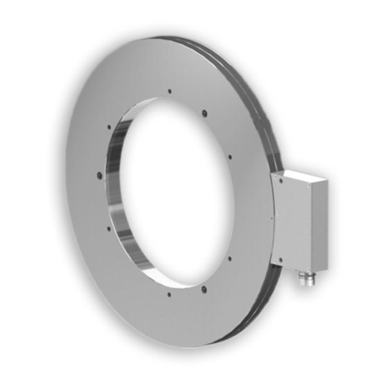
- Page 1 Montage- und Betriebsanleitung Mounting and operating instructions MHGE 400 - HDmag Lagerloser Drehgeber - inkremental Magnetische Abtastung Encoder without bearings - incremental Magnetic sensing...
-
Page 2: Table Of Contents
Montage / Mounting Inhaltsverzeichnis Inhaltsverzeichnis Allgemeine Hinweise ..............................Sicherheitshinweise ..............................Vorbereitung .................................. Lieferumfang ..............................3.1.1 Geberrad je nach Version ........................3.1.2 Abtastkopf ............................... Zur Montage erforderlich (nicht im Lieferumfang enthalten) ........... Zur Demontage erforderlich (nicht im Lieferumfang enthalten) ..........Erforderliches Werkzeug (nicht im Lieferumfang enthalten) ........... - Page 3 Montage / Mounting Table of contents Table of contents General notes ................................Security indications ..............................Preparation ..................................Scope of delivery ............................3.1.1 Encoder wheel depending on version ....................3.1.2 Sensor head ..............................Required for mounting (not included in scope of delivery) ............
-
Page 4: Allgemeine Hinweise
Das Produkt enthält wertvolle Rohstoffe, die recycelt werden können. Wenn immer möglich sollen Altgeräte lokal am entsprechenden Sammeldepot entsorgt werden. Im Bedarfsfall gibt Baumer den Kunden die Möglichkeit, Baumer-Produkte fachgerecht zu entsor- gen. Weitere Informationen siehe www.baumer.com. MB202 - 11069322... -
Page 5: General Notes
Whenever possible, waste electrical and electronic equipment should be disposed locally at the authorized collection point. If necessary, Baumer gives customers the opportunity to dispose of Baumer products profession- ally. For further information see www.baumer.com. -
Page 6: Sicherheitshinweise
Montage / Mounting Sicherheitshinweise Sicherheitshinweise Verletzungsgefahr durch rotierende Wellen Haare und Kleidungsstücke können von rotierenden Wellen erfasst werden. • Vor allen Arbeiten alle Betriebsspannungen ausschalten und Maschinen stillsetzen. Zerstörungsgefahr durch mechanische Überlastung • Gerät nie senkrecht - das heißt auf das Magnetband - stellen. •... -
Page 7: Security Indications
Montage / Mounting Security indications Security indications Risk of injury due to rotating shafts Hair and clothes may become tangled in rotating shafts. • Before all work switch off all voltage supplies and ensure machinery is stationary. Risk of destruction due to mechanical overload •... -
Page 8: Vorbereitung
Montage / Mounting Vorbereitung / Preparation Vorbereitung Preparation Lieferumfang Scope of delivery 3.1.1 Geberrad je nach Version 3.1.1 Encoder wheel depending on version Geberrad für Schraubmontage und Heiß- Encoder wheel for screw mounting and schrumpfmontage shrink fit mounting (MHGE 400 x5 G) (MHGE 400 x5 G) Inkrementalspur Incremental track... - Page 9 Vorbereitung / Preparation Montage / Mounting 3.1.1 Geberrad je nach Version 3.1.1 Encoder wheel depending on version Geberrad für Spannsatzmontage Encoder wheel for clamping set mounting (MHGE 400 x5 Z, MHGE 400 x5 Y) (MHGE 400 x5 Z, MHGE 400 x5 Y) Inkrementalspur Incremental track Nullimpulsspur...
-
Page 10: Abtastkopf
Montage / Mounting Vorbereitung / Preparation Lieferumfang Scope of delivery 3.1.2 Abtastkopf 3.1.2 Sensor head Abtastkopf mit Standard-Signalverarbeitung Sensor head with standard signal processing Zyl. Senkung für M8, ISO 4762 Cyl. counterbore for M8, ISO 4762 Flanschdose M23, 12-polig, Stiftkontakte, Flange connector M23, 12-pin, male, CCW, linksdrehend, siehe Abschnitt 6.3.3. -
Page 11: Zur Montage Erforderlich (Nicht Im Lieferumfang Enthalten)
Vorbereitung / Preparation Montage / Mounting Zur Montage erforderlich Required for mounting (nicht im Lieferumfang enthalten) (not included in scope of delivery) Sensorkabel HEK 8, als Zubehör erhältlich, Sensor cable HEK 8, available as accessory, siehe Abschnitt 6.5. see section 6.5. Befestigungsschraube ISO 4762, M6x35 mm Fixing screw ISO 4762, M6x35 mm bei Geberrad für Schraubmontage, siehe 1... -
Page 12: Montage
Montage / Mounting Montage Mounting Montage des Geberrades Mounting the encoder wheel 4.1.1 Schraubmontage 4.1.1 Screw mounting (MHGE 400 x5 G) (MHGE 400 x5 G) 5 mm Zul. Anzugsmoment: Max. tightening torque: = 5 Nm øA , øC = 140...340 mm Antriebswelle einfetten. -
Page 13: Spannsatzmontage (Mhge 400 X5 Z, Mhge 400 X5 Y)
Montage / Mounting Montage des Geberrades Mounting the encoder wheel 4.1.3 Spannsatzmontage 4.1.3 Clamping set mounting (MHGE 400 x5 Z, MHGE 400 x5 Y) (MHGE 400 x5 Z, MHGE 400 x5 Y) 4 mm (øA ≤150 mm) 4 mm (øA >150 mm) Zul. -
Page 14: Montage Des Abtastkopfes
Montage / Mounting Montage des Abtastkopfes Mounting the sensor head Geberrad Encoder wheel Befestigungsmöglichkeit für den Abtastkopf (Beispiel). Fixing element for the sensor head (example). Zul. Anzugsmoment: Max. tightening torque: Typenschild = 8...10 Nm Type label 6 mm 3.1 * ±3 mm Zulässiger Axialversatz zwischen Abtastkopf und Geberrad... -
Page 15: Abmessungen
Abmessungen / Dimensions Montage / Mounting Abmessungen Dimensions Schraubmontage oder Heißschrumpf- Screw mounting or shrink fit mounting montage (MHGE 400 x5 G) (MHGE 400 x5 G) 3x Abdrückgewinde M6 Drehrichtung positiv 3x Jack-screw thread M6 Positive rotating direction 6x ø6.5 øA = 140...340 øB = øA +20... -
Page 16: Spannsatzmontage (Mhge 400 X5 Z, Mhge 400 X5 Y)
Montage / Mounting Abmessungen / Dimensions Spannsatzmontage Clamping set mounting (MHGE 400 x5 Z, MHGE 400 x5 Y) (MHGE 400 x5 Z, MHGE 400 x5 Y) Drehrichtung positiv Positive rotating direction øA = 70...200 Ansicht A View A Nullimpuls- markierung Zero pulse marker Luftspalt... -
Page 17: Elektrischer Anschluss
Elektrischer Anschluss / Electrical connection Montage / Mounting Elektrischer Anschluss Electrical connection Beschreibung der Anschlüsse Terminal significance Betriebsspannung +UB; + Voltage supply Masseanschluss ; ; GND; 0V Ground Erdungsanschluss (Gehäuse) Earth ground (housing) Ausgangssignal Kanal 1 A+; K1 Output signal channel 1 Ausgangssignal Kanal 1 invertiert A−;... -
Page 18: Ausgangssignale
Montage / Mounting Elektrischer Anschluss / Electrical connection Ausgangssignale Output signals 6.2.1 Mit Rechtecksignalen: 6.2.1 With square-wave signals: (RN..C, TN..C, HN..C und UN..C) (RN..C, TN..C, HN..C and UN..C) Signalfolge bei positiver Drehrichtung, A−... -
Page 19: Abtastkopf Mit Flanschdose
Elektrischer Anschluss / Electrical connection Montage / Mounting Abtastkopf mit Flanschdose Sensor head with flange connector 6.3.1 Kabelanschluss Rundsteckverbinder - 6.3.1 Cable connection mating connector - Schritt 1 Step 1 Kabelschirm Cable shield Ansicht X Löteinsatz, Belegung siehe ø7...12 mm Abschnitt 6.3.3. -
Page 20: Kabelanschluss Rundsteckverbinder - Schritt 2
Montage / Mounting Elektrischer Anschluss / Electrical connection 6.3.2 Kabelanschluss Rundsteckverbinder - 6.3.2 Cable connection mating connector - Schritt 2 Step 2 Handfest Hand-tight Ansicht Y siehe Abschnitt 6.3.3. * Siehe Seite 7 View Y see section 6.3.3. See page 7 6.3.3 Stiftbelegung Flanschdose 6.3.3... -
Page 21: Abtastkopf Mit Klemmenkasten
Demontage / Dismounting Montage / Mounting Abtastkopf mit Klemmenkasten Sensor head with terminal box 6.4.1 Kabelanschluss Anschlussplatine 6.4.1 Cable connection connecting board Ansicht Z 22 mm siehe Abschnitt 6.4.2. View Z see section 6.4.2. TX 20 ø5...13 mm Kabelschirm Cable shield Zul. -
Page 22: Anschlussbelegung Anschlussplatine
There is no connection between Sensorkabel HEK 8 (Zubehör) Sensor cable HEK 8 (accessory) Es wird empfohlen, das Baumer Hübner Baumer Hübner sensor cable HEK 8 is Sensorkabel HEK 8 zu verwenden oder recommended. As a substitute a shielded ersatzweise ein geschirmtes, paarig ver- twisted pair cable should be used. -
Page 23: Demontage
Demontage / Dismounting Montage / Mounting Demontage Dismounting Demontage des Abtastkopfes Dismounting the sensor head 6 mm 3.1 * * Siehe Seite 7 oder 8 See page 7 or 8 Vor Demontage des Gerätes alle Disconnect all electric connections elektrischen Verbindungen trennen and ensure machinery is stationary und Maschinen stillsetzen. -
Page 24: Demontage Des Geberrades
Montage / Mounting Demontage / Dismounting Demontage des Geberrades Dismounting the encoder wheel 7.2.1 Schraubmontage 7.2.1 Screw mounting (MHGE 400 x5 G) (MHGE 400 x5 G) 5 mm 5 mm * Siehe Seite 5 oder 8 See page 5 or 8 MB202 - 11069322 Baumer_MHGE400_II_DE-EN (19A3) -
Page 25: Heißschrumpfmontage (Mhge 400 X5 G)
Demontage / Dismounting Montage / Mounting Demontage des Geberrades Dismounting the encoder wheel 7.2.2 Heißschrumpfmontage 7.2.2 Shrink fit mounting (MHGE 400 x5 G) (MHGE 400 x5 G) 5 mm 7.2.3 Spannsatzmontage 7.2.3 Clamping set mounting (MHGE 400 x5 Z, MHGE 400 x5 Y) (MHGE 400 x5 Z, MHGE 400 x5 Y) 4 mm (øA ≤150 mm) 4 mm (øA >150 mm) -
Page 26: Technische Daten
Montage / Mounting Technische Daten Technische Daten Technische Daten - elektrisch • Störfestigkeit: EN 61000-6-2 • Störaussendung: EN 61000-6-3 • Zulassungen: UL-Zulassung / E217823 Option: DNV-Zulassung Technische Daten - elektrisch (Rechteck) • Betriebsspannung (Signale): 4,75...30 VDC (TTL/RS422) 5 VDC ±5 % (TTL/RS422) 10...30 VDC (HTL) -
Page 27: Technische Daten - Mechanisch
Montage / Mounting Technische Daten - mechanisch • Abtastkopf: Standard-Signalverarbeitung • Baugröße (Flansch): ø405,4 mm • Wellenart: ø70...340 mm (durchgehende Hohlwelle) (je nach Bestellung) • Axiale Toleranz: ±3 mm (Rad/Kopf) • Radiale Toleranz: 0,1...2,2 mm (Rad/Kopf) • Schutzart DIN EN 60529: IP67 (Kopf) IP68 (Rad) •... -
Page 28: Technical Data
Montage / Mounting Technical data Technical data Technical data - electrical ratings • Interference immunity: EN 61000-6-2 • Emitted interference: EN 61000-6-3 • Approvals: UL approval / E217823 Option: DNV approval Technical data - electrical ratings (square-wave) • Voltage supply (Signals): 4,75...30 VDC (TTL/RS422) 5 VDC ±5 %... -
Page 29: Technical Data - Mechanical Design
Montage / Mounting Technical data - mechanical design • Sensor head: Standard signal processing • Size (flange): ø405.4 mm • Shaft type: ø70...340 mm (through hollow shaft) (as ordered) • Axial tolerance: ±3 mm (wheel/head) • Radial tolerance: 0.1...2.2 mm (wheel/head) • Protection DIN EN 60529: IP67 (head) IP68 (wheel) •... -
Page 30: Zubehör
Montage / Mounting Zubehör / Accessories Zubehör Accessories • Sensorkabel für Drehgeber • Sensor cable for encoders HEK 8 HEK 8 • Werkzeugset: • Tool kit: Bestellnummer 11068265 Order number 11068265 • Diverse Interpolatoren/Splitter/ • Various interpolators/splitters/ Vervielfacher auf Anfrage multipliers on request * Siehe Abschnitt 3 See section 3... - Page 31 MB202 - 11069322 Baumer_MHGE400_II_DE-EN (19A3)
- Page 32 Baumer Hübner GmbH P.O. Box 12 69 43 · 10609 Berlin, Germany Phone: +49 (0)30/69003-0 · Fax: +49 (0)30/69003-104 info@baumerhuebner.com · www.baumer.com/motion MB202 - 11069322 Baumer_MHGE400_II_DE-EN (19A3-15.10.2019)