Advertisement
Quick Links
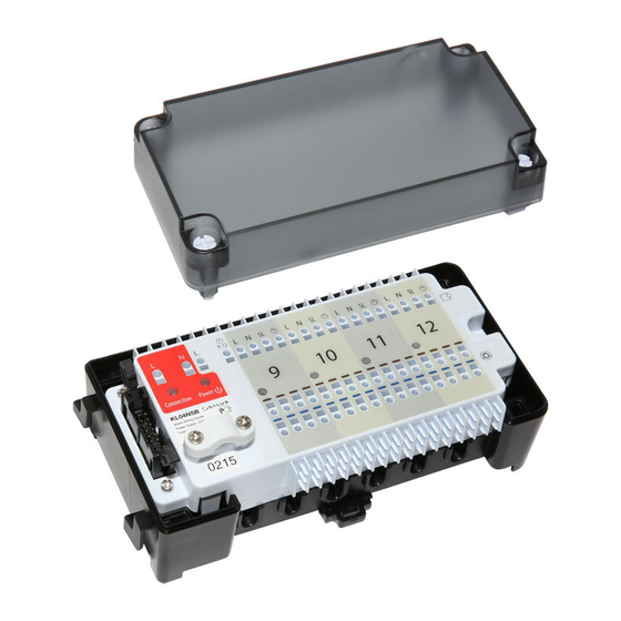
Wiring centre extension for 4-zone UFH
Model: KL04NSB
Manual
Head Office: SALUS Controls plc
T: +44 (0) 1226 323961
SALUS House
E: sales@salus-tech.com
Dodworth Business Park South,
Whinby Road, Dodworth,
Barnsley S75 3SP, UK.
www.salus-controls.com
SALUS Controls is a member of the Computime Group.
Maintaining a policy of continuous product development SALUS Controls plc reserve
the right to change specification, design and materials of products listed in this
brochure without prior notice.
Introduction
The KL04NSB is an easy to connect four zone extension for the KL08NSB wiring centre. It expands
the system to up to12 zones in total
08NSB
Product compliance
This product complies with the essential requirements and other relevant provisions of the following
EU Directives: EMC 2014/30/EU, Low Voltage Directive LVD 2014/35/EU and RoHS directive 2011/65/EU.
The full text of the EU Declaration of Conformity is available at the following internet address:
www.saluslegal.com.
Safety information
Use in accordance with national and EU regulations. Device is intended for indoor use only in dry
conditions. Product for indoor use only. Installation must be carried out by a qualified person in
accordance to national and EU regulations.
Before attempting to setup and install, make sure that the devices is not connected to any power source.
Installation must be carried out by a qualified person. Incorrect installation may cause damage to
the devices. The KL04NSB should not be installed in areas where it may be exposed to water or damp
conditions.
Technical Information
KL08NSB
Power Supply
230 V AC
Total Load Max
3 A
Outputs
Terminals for actuators (230 V)
Dimensions [mm]
163 x 85 x 67
Wiring centre description
1. Serial connector
2. Power supply
3. Connection indicator
4. Power indicator
1. Serial connector
The Serial connector is used to connect the KL08NSN with the KL04NSB extension module to add
functionality and support up to12 zones
KL08NSB
2. Power Supply
230 V AC
L
N
Reset
0
O
KL08NSB
KL04NSB
1
2
3
4
3. Connection indicator
Reset
After successful connection of KL08NSB with KL04NSB extension module
0
up constantly.
O
KL04NSB
2
1
3
4
Reset
0
O
KL08NSB
KL04NSB
1
2
3
4
Reset
0
O
Reset
0
O
KL04NSB
1
2
3
4
1
2
3
4
Power supply for wiring centre is 230 V ~ 50Hz.
Two wire installation should be made in accordance
with the applicable regulations
Reset
0
O
1
2
3
4
red
LED will light
5. NSB function terminals
6. Actuators connection
7. Thermostats connection
5
7
group iii
4. Power indicator
After connecting of KL04NSB to the power supply, the Power
KL04NSB
5. NSB (Night Set Back reduction) function
NSB function is activated in non-programmable Salus thermostats of the Expert NSB, HTR, BTR series
via external signal. NSB 230 V signal (night-time temperature reduction) is sent via an external timer
or programmable thermostat connected to the wiring centre. Non-programmable thermostats are
receiving NSB signal and reducing setpoint temperature (by switching to eco mode). All thermostats
have to be connected using a 4-wire cable (min. 4 x 0,75 mm
• OPTION 1
• OPTION 2
One Master thermostat which
jumpers
is common for thermostats
from Group 1, Group 2 and
Group 3 (one programmable
thermostat
e.g.
VS30,
L 1-4
5-8 9-12
L 1-4
other thermostats are non-
programmable e.g. VS35).
• OPTION 3
• OPTION 4
One external clock which is
jumpers
common for thermostats
from Group 1, Group 2
KL04NSB
and Group 3 (one external
clock + daily regulators e.g.
L 1-4
5-8 9-12
VS35).
L 1-4 5-8 9-12
Note: Terminals 1-4 and 5-8 are located in the KL08NSB wiring centre, while terminals 9-12
are located in the KL04NSB extension module.
6
red
LED will light up.
2
, max. 4 x 1,5 mm
2
).
Three Master thermostats.
no jumpers
One for Group 1 , one for
Group 2 and one for Group
3 (three programmable
thermostats e.g. VS30,
5-8 9-12
other thermostats are non-
programmable e.g., VS35).
Three external clocks. One
for Group 1, one for Group 2
and one for Group 3 (three
external clocks + non-
programmable
regulators
e.g. VS35).
Advertisement

Related Manuals for Salus KL04NSB


Summary of Contents for Salus KL04NSB
- Page 1 Installation must be carried out by a qualified person. Incorrect installation may cause damage to thermostat e.g. VS30, thermostats e.g. VS30, the devices. The KL04NSB should not be installed in areas where it may be exposed to water or damp L 1-4 5-8 9-12 L 1-4 5-8 9-12...
- Page 2 When mounting on a DIN rail, open the hooks on the 230 V AC back of the housing. Connect the serial cable to the KL08NSB and KL04NSB connector . 12 mm 12 mm L N SL Make sure that all the wires are...