Emerson Wireless 1420 Gateway Reference Manual
Hide thumbs
Also See for Wireless 1420 Gateway:
- Reference manual (88 pages) ,
- Quick start manual (36 pages) ,
- Quick installation manual (20 pages)

Related Manuals for Emerson Wireless 1420 Gateway


Summary of Contents for Emerson Wireless 1420 Gateway
- Page 1 Reference Manual 00809-0200-4420, Rev HE September 2020 Emerson Wireless 1420 Gateway...
- Page 2 The products described in this document are NOT designed for nuclear-qualified applications. Using non-nuclear qualified products in applications that require nuclear-qualified hardware or products may cause inaccurate readings.For information on ™ Rosemount nuclear-qualified products, contact your local Emerson Sales Representative.
-
Page 3: Table Of Contents
Chapter 6 Troubleshooting...................... 57 6.1 Service support..........................57 6.2 Troubleshooting Tables......................57 6.3 Return of materials........................61 Chapter 7 Glossary........................63 Appendix A Specifications and Reference Data................65 A.1 Functional specifications......................65 A.2 Physical specifications....................... 66 A.3 Communication specifications....................67 Emerson.com/Rosemount... - Page 4 C.2 Latency considerations in control logic design and operation............ 79 C.3 Requirements..........................79 C.4 Mounting and connecting......................79 C.5 Setup............................80 Appendix D Redundancy......................85 D.1 Overview...........................85 D.2 Requirements..........................85 D.3 Setup redundant gateways......................85 D.4 Mounting and connections......................88 D.5 Diagnostics..........................92 D.6 Gateway replacement....................... 94 Emerson.com/Rosemount...
-
Page 5: Chapter 1 Introduction
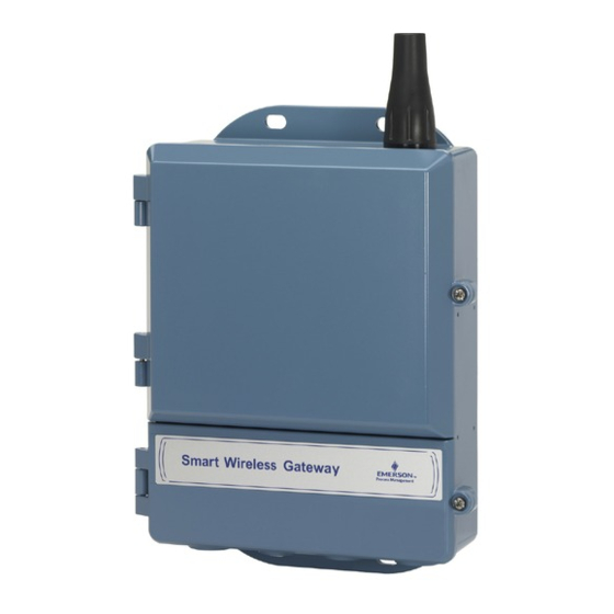
September 2020 Introduction Product overview ™ ® The Emerson Wireless 1420 Gateway (Gateway) connects WirelessHART self-organizing ® networks with host systems and data applications. Modbus communications over RS-485 or Ethernet LAN provide universal integration and system interoperability. The optional OPC functionality from the Gateway offers a means to connect to newer systems and applications while providing a richer set of data. -
Page 6: Product Recycling/Disposal
Appendices provide additional and more specific information on a variety of subjects including Specifications and Reference Data and Product Certifications. Product recycling/disposal Consider recycling equipment and packaging. Dispose of the product and packaging in accordance with local and national legislation. Emerson.com/Rosemount... -
Page 7: Chapter 2 Configuration
Configuration Overview ™ This section describes how to connect to the Emerson Wireless 1420 Gateway (Gateway) for the first time and what settings should be configured before placing it on a live control network. It is important to note that some Gateways are used in stand-alone applications and do not reside on a network. - Page 8 Connecting to the Gateway's secondary Ethernet port will require different network settings. See Table 2-1 for additional network settings. Table 2-1: Default IP Addresses Gateway PC/laptop Subnet Ethernet 1 192.168.1.10 192.168.1.12 255.255.255.0 Ethernet 2 192.168.2.10 192.168.2.12 255.255.255.0 Ethernet 1 (DeltaV Ready) 10.5.255.254 10.5.255.200 255.254.0.0 Emerson.com/Rosemount...
- Page 9 Determining Gateway compatibility with Power over Ethernet (PoE) Figure 2-1: Legacy Gateway Terminal Block A. Case B. Ethernet 2 with power (covered) C. Ethernet 2 (secondary) D. Ethernet 1 (primary) E. 24 VDC (nominal) power input ® F. Serial Modbus G. Not used Emerson.com/Rosemount...
- Page 10 The Gateway can either source or receive power over an Ethernet port; it cannot do both at the same time. If using the Gateway as a PSE, the total additional power requirements of the PD must be factored into the total input power requirements of the power supply for the Gateway. It is Emerson.com/Rosemount...
- Page 11 “PoE+” or “PoE plus”, provides up to 25.5 W of power. The 2009 standard prohibits a powered device from using all four pairs for power. For more information on PoE and frequently asked questions, refer to Emerson Wireless 1420 Gateway with Power over Ethernet Technical Note Power over Ethernet (PoE).
- Page 12 Table 2-2: Role Based Access User Accounts Role User name Web interface access Executive exec Read-only access Operator oper Read-only access ® Maintenance maint Configure HART device settings ® Configure Modbus communications Configure Modbus register mapping Configure OPC browse tree Configure Active Advertising Emerson.com/Rosemount...
- Page 13 Each of the initial passwords for the user accounts is default. It is recommended, for security purposes, that these passwords are changed. The administrator password should be appropriately noted when changed. If it is lost, contact Emerson for technical support. To change the user accounts passwords: Procedure 1.
- Page 14 IP address, as well as other TCP/IP network settings. Request the following configuration items from the network administrator: • Specify an IP address, or use a DHCP server • Hostname • Domain Name • IP address • Netmask • Gateway Emerson.com/Rosemount...
- Page 15 Once the IP Address of the Gateway has been changed, communications to the web interface will be lost. Restart the web browser, then log back into the Gateway using the new IP address and other TCP/IP network settings. The PC/laptop TCP/IP network settings may need to be changed. Emerson.com/Rosemount...
- Page 16 4. Enter a save location and file name. 5. Select Save. 6. Select Return to form. Note System backup contains user passwords and keys used for encrypting communication. Store downloaded system backups in a secure location. These files themselves are also encrypted. Emerson.com/Rosemount...
-
Page 17: Chapter 3 Installation
September 2020 Installation Overview ™ This section describes how to properly mount the Emerson Wireless 1420 Gateway (Gateway) and make electrical connections, including electrical wiring, grounding, and host system connections. This section also describes how to mount the optional remote antenna. - Page 18 1. Insert one u-bolt around the pipe, through the top mounting holes of the Gateway enclosure, and through the washer plate. 2. Use a -in. socket-head wrench to fasten the nuts to the u-bolt. 3. Repeat for the second u-bolt and the lower mounting holes. Emerson.com/Rosemount...
-
Page 19: Remote Antenna (Optional)
2. Using a 1/2-in. socket-head wrench, attach the Gateway to the support bracket with four 15/16-in. bolts. Remote antenna (optional) The remote antenna options provide flexibility for mounting the Gateway based on wireless connectivity, lightning protection, and current work practices. Emerson.com/Rosemount... - Page 20 If the supplied remote mount antenna kit is not installed per these instructions, Emerson is not responsible for wireless performance or non-compliance with spectrum regulations.
- Page 21 1 ft. (0,3 m) from the lightning arrestor. 5. Connect the lightning arrestor to the Gateway using the supplied coaxial cable. 6. Use the coaxial sealant to seal each connection between the Gateway, lightning arrestor, cable, and antenna. Emerson.com/Rosemount...
- Page 22 The remote mount antenna kit includes coaxial sealant for the cable connections for the lightning arrestor, antenna, and Gateway. The coaxial sealant must be applied to guarantee performance of the wireless field network. See Figure 3-5 for details on how to apply weather proofing. Emerson.com/Rosemount...
-
Page 23: Connecting
Ground the Gateway by connecting the external grounding lug to earth ground. The connection should be 1Ω or less. The external ground plug is located below the Gateway enclosure and is identified by the following symbol: Emerson.com/Rosemount... - Page 24 C. Ethernet 1 (primary) D. 24 VDC (nominal) power input E. Serial Modbus Ethernet connections should use Cat5E or better shielded cable to connect to an Ethernet hub, switch, or router. The maximum cable length should not exceed 328ft (100 m). Emerson.com/Rosemount...
- Page 25 Only terminated at one end typically at the power supply end. If the existing data bus uses a 4 wire Full Duplex configuration, see Figure 3-8 to convert to a 2-wire Half Duplex configuration. Figure 3-8: Convert from Full to Half Duplex Emerson.com/Rosemount...
- Page 26 Switch 2 is connected to a 120 Ω terminating resistor. This resistor is used to dampen signal reflections on long cable runs. RS-485 specifications indicate that the data bus should be terminated at both ends (Figure 3-10). However termination should only be used with high data rates (above 115 kbps) and long cable runs. Emerson.com/Rosemount...
- Page 27 The wires that would carry power and how • Devices that could source power and devices that could be powered • Supplied wattage would be up to 15 Watts (in 2009, IEEE 802.3at was adopted, which allowed power up to 25 Watts) Emerson.com/Rosemount...
- Page 28 PoE will function. Before 2003, there was no standard and companies developed their own techniques for powering over an Ethernet cable. These techniques are not always interoperable. Before the standard, they used the term PoE on many of their Emerson.com/Rosemount...
- Page 29 PoE+ and the load of the Gateway (approximately 3 to 4 Watts) can add up to 30 Watts of power; because of this the proper Ethernet cable must be selected depending on the length of the cable run. Emerson.com/Rosemount...
- Page 30 N4, which typically take a longer time, would ship with PoE at a later date. Contact your Emerson Sales Representative to find out if a particular code has been approved for PoE. It should be also noted that all PoE units shipped are configured as a PoE PD on port 1. By using the jumpers included with the unit, the installer configures the unit during installation as to mode and port of PoE operation if desired.
- Page 31 The simplest way to check for IEEE PoE capability is to open the upper door on the 1420 Gateway and the see how the computer board is mounted. In the newer hardware, the board is mounted horizontally. The old hardware the computer board was mounted vertically. Emerson.com/Rosemount...
- Page 32 C. 1420 without PoE Are there other changes in the 1420 Gateway with the new hardware? Emerson's Quality Policy is to continuously improve our products year after year. The following is a list of some improvements with the new hardware: •...
- Page 33 EN: Enabled; this enables the PSE operation • DIS: Disabled; this disables the PSE operation Note Only one port and one mode of operation (PD or PSE) can be selected at a time. Any other combination of jumpers is invalid. Emerson.com/Rosemount...
- Page 34 Installation Reference Manual September 2020 00809-0200-4420 Emerson.com/Rosemount...
-
Page 35: Commissioning
™ Emerson Wireless 1420 Gateway (Gateway). This software is not required for the wireless field network to operate; however, it will aid in secure host integration as well as wireless field device configuration. The following table describes what items are installed and on which disk they can be found. -
Page 36: Software Installation
Security Setup Utility The Gateway provides significant flexibility by offering many different interface options. Users should be aware that with this flexibility comes certain risks. Opening the non- secure versions of an industrial protocol can expose significant information, some of it Emerson.com/Rosemount... - Page 37 00809-0200-4420 September 2020 sensitive, about the wireless network. For this reason, Emerson encourages end users to use Emerson’s Security Setup Utility to secure the industrial protocols. Users running non- secure versions of the industrial protocols are encouraged to make sure the Gateway is running on a secure network and following security best practices.
-
Page 38: Ams Wireless Configurator
® integrated operating environment that leverages the full capabilities of WirelessHART including embedded data trending, charting, and graphical display capabilities provided by enhanced EDDL technology. • Display and modify device configuration • View device diagnostics • View process variables Emerson.com/Rosemount... - Page 39 7. Repeat Step 6 if multiple Gateways need to be added. 8. Check the box to Enable Secure Communications with the Gateway. 9. Select Finish to close the configuration window. 10. Select Close to exit the Network Configuration application. Emerson.com/Rosemount...
-
Page 40: Licensing And Credits
9. Check the box to Include WirelessHART Adapter. 10. Select Finish to close the configuration window. 11. Select Close to exit the Network Configuration application. Licensing and credits The latest licensing agreements are included on each disk of the software pack. Emerson.com/Rosemount... - Page 41 Reference Manual Commissioning 00809-0200-4420 September 2020 “This product includes software developed by the OpenSSL Project for use in the OpenSSL Toolkit (www.openssl.org)” Emerson.com/Rosemount...
- Page 42 Commissioning Reference Manual September 2020 00809-0200-4420 Emerson.com/Rosemount...
-
Page 43: Operation And Maintenance
September 2020 Operation and Maintenance Overview ™ This section describes how to connect the Emerson Wireless 1420 Gateway (Gateway) to a host system and integrate data gathered from the field device network. It covers network architectures, security, and data mapping. - Page 44 A Fiber optic connection supports Modbus TCP, OPC, AMSWireless Configurator, and HART TCP protocols. Using this connection type, the Gateway is wired to a fiber optic switch (see Figure 5-2). Note A fiber optic connection requires a third party copper Ethernet to fiber optic Ethernet converter. Emerson.com/Rosemount...
- Page 45 An RS-485 connection supports Modbus RTU protocol. Using this connection type, the Gateway is wired to an RS-485 bus which typically leads to a serial I/O card or Modbus I/O card (see Figure 5-3). Up to 31 Gateways can be connected to a single I/O card in this manner. Emerson.com/Rosemount...
-
Page 46: Internal Firewall
TCP ports for communication protocols are user configurable, including user specified port numbers and the ability to disable ports. The Gateway’s internal firewall settings can be found by navigating to System Settings → Protocols → Protocols and Ports. Emerson.com/Rosemount... -
Page 47: Modbus
It is import that the Modbus communication settings in the Gateway match the setting in the Modbus master or client. Refer to host system documentation for more information on how to configure these settings. The Modbus communication settings can be found by navigating to System Settings → Protocols → Modbus. Emerson.com/Rosemount... - Page 48 Floating point representation: This setting determines if the Gateway uses floating point values or integer values. There are three options for this setting. • Float uses 32 bit floating point values. • Round rounds the data value to the nearest whole number. Emerson.com/Rosemount...
- Page 49 Register Mapping is the process of assigning data points from wireless field devices to Modbus registers. These registers can then be read by a Modbus master or client. Modbus register mapping can be found by navigating to System Settings → Protocols → Modbus. Emerson.com/Rosemount...
- Page 50 Point Name: This is a two part name for the data point. The first part is the HART Tag of the wireless field device which is producing the data. The second part is the parameter of the wireless field device. Emerson.com/Rosemount...
- Page 51 Offset: This value is added to the data value for the purpose of scaling integers. Offset is only required if scaled is chosen on the Modbus communications page and globe gain and offset is not chosen. Emerson.com/Rosemount...
- Page 52 49023 8-bit unsigned int SYSTEM_DIAG.ADDITIONAL_STATUS_9 49024 8-bit unsigned int SYSTEM_DIAG.ADDITIONAL_STATUS_10 49025 8-bit unsigned int SYSTEM_DIAG.ADDITIONAL_STATUS_11 49026 8-bit unsigned int SYSTEM_DIAG.ADDITIONAL_STATUS_12 49027 8-bit unsigned int SYSTEM_DIAG.UNREACHABLE 49028 32-bit int SYSTEM_DIAG.UPTIME 49029 32-bit int SYSTEM_DIAG.TEST_BOOLEAN 49031 Boolean SYSTEM_DIAG.TEST_BYTE 49032 8-bit int Emerson.com/Rosemount...
-
Page 53: Ethernet/Ip
DeltaV system see #unique_72/ unique_72_Connect_42_Ram24704. Note Ethernet/IP can be integrated with any approved Ethernet/IP ODVA member. Other protocols such as HARTIP are still functional within the Gateway. See the Emerson Wireless Gateway Product Data Sheet for ordering options. Emerson.com/Rosemount... - Page 54 Positive infinity is reported if the value’s associated status indicates a critical failure. -Inf Negative infinity is reported if the value’s associated status indicates a critical failure. Other User defined value is reported if the value’s associated status indicates a critical failure. Emerson.com/Rosemount...
- Page 55 Input Instance Ethernet/IP Input Static Assembly Instance - 496 bytes Output Ethernet/IP Output Static Assembly Instance - 496 bytes Instance Member Ethernet/IP Instance Member in which data will get produced or consumed Point Name Assigned data point in the format HARTtag.parameter Emerson.com/Rosemount...
- Page 56 Ethernet/IP communications settings). 3. Repeat for each new data point. 4. Select Submit. 5. When changes have been accepted, select Return to form. Table 5-1 for options of parameters that can be mapped. Emerson.com/Rosemount...
-
Page 57: Chapter 6 Troubleshooting
Note For more information see the Emerson Wireless Gateway User Interface Terminology Guide. This section provides basic troubleshooting tips for the Emerson Wireless Field Network. To receive technical support by phone: Global Service Center Software and Integration Support United States 1-800-833-8314 International +63-2-702-1111 Customer Central Technical Support, quoting, and order related questions United States 1-800-999-9307 (7:00 a.m. - Page 58 2. Right click on wireless network and select rebuild hierarchy. Gateway Wireless device 1. Install latest device support files from AMS Wireless Configurator. Go to appears with red Emerson.com/Automation/AMS. ® HART symbol Device 1. Verify whether current or historical information is being displayed. This configuration setting is displayed at the bottom of each device configuration screen.
- Page 59 2. Verify the Modbus TCP communications settings in the Gateway. Log on to the Gateway and navigate to SETUP → MODBUS → COMMUNICATIONS. 3. Verify Modbus register mapping in the Gateway. Log on to the Gateway and navigate to SETUP → MODBUS → MAPPING. Emerson.com/Rosemount...
- Page 60 5. Verify network firewall and port settings. Table 6-6: Troubleshooting EtherNet/IP Issue Troubleshooting steps The Gateway is not publishing 1. Verify connection is established with Ethernet/IP. Navigate to SETUP → SECURITY → PROTOCOLS. the parameters ® 2. Reference Emerson Wireless Gateway to Allen-Bradley Integration Manual. Emerson.com/Rosemount...
-
Page 61: Return Of Materials
00809-0200-4420 September 2020 Return of materials To expedite the return process outside of North America, contact your Emerson representative. Within the United States, call the Emerson Response Center toll-free number 1-800-654-7768. The center, which is available 24 hours a day, will assist you with any needed information or materials. - Page 62 Troubleshooting Reference Manual September 2020 00809-0200-4420 Emerson.com/Rosemount...
-
Page 63: Chapter 7 Glossary
Glossary This glossary defines terms used throughout this manual or that appear in the web ™ interface of the Emerson Wireless 1420 Gateway (Gateway). Term Definition Access Control List A list of all devices that are approved to join the network. Each device will also have a unique join key. - Page 64 WirelessHART field devices that are a part of the wireless field network. Device(s) Wireless Field Network WirelessHART network, consisting of Gateway and multiple wireless field devices. Wireless Plant Network Industrial Wi-Fi network, used to integrate the Wireless Field Network into the control network. Emerson.com/Rosemount...
-
Page 65: Appendix A Specifications And Reference Data
Operating current draw is based on 3.6 Watts power consumption. A. Current (mA) B. Voltage (VDC) Momentary startup current draw up to twice operating current draw. A.1.4 Radio frequency power output from antenna Maximum of 10 mW (10 dBm) EIRP Emerson.com/Rosemount... -
Page 66: Physical Specifications
Integrated Omni-directional Antenna Optional remote mount Omni-directional Antenna Physical specifications A.2.1 Weight 10 lb. (4.54 kg) A.2.2 Material of construction Housing ® Low-copper aluminum, NEMA Paint Polyurethane Cover gasket Silicone Rubber Antenna Integrated Antenna: PBT/PC Remote Antenna: Fiber Glass Emerson.com/Rosemount... -
Page 67: Communication Specifications
Protocols: Modbus TCP, OPC, EtherNet/IP , HART-IP , https (for Web Interface) Wiring: Cat5E shielded cable Wiring distance: 328 ft (100 m) A.3.3 Modbus Supports Modbus RTU and Modbus TCP with 32-bit floating point values, integers, and scaled integers. Modbus Registers are user-specified. Emerson.com/Rosemount... -
Page 68: Self-Organizing Network Specifications
Ethernet security specifications Secure Sockets Layer (SSL) enabled (default) TCP/IP communications A.5.2 Gateway access Role-based Access Control (RBAC) including Administrator, Maintenance, Operator, and Executive. Administrator has complete control of the Gateway and connections to host systems and the self-organizing network. Emerson.com/Rosemount... - Page 69 Inspects both incoming and outgoing packets. A.5.5 Third party certification Wurldtech: Achilles Level 1 certified for network resiliency National Institute of Standards and Technology (NIST): Advanced Encryption Standard (AES) Algorithm conforming to Federal Information Processing Standard Publication 197 (FIPS-197). Emerson.com/Rosemount...
-
Page 70: Dimensional Drawings
(71,4) (64,14) (121) 2.93 3.08 (78) (74,42) 1.59 (40) 12.03 (306) 3.99 (101) 11.15 (283) 2.96 (75) A. Lower cover (remove for electrical connections) B. Ground lug C. 1/2-in. NPT conduit connection (four places) Dimensions are in inches (millimeters). Emerson.com/Rosemount... - Page 71 Smart Wireless Gateway. Lightning protection is included on all the options. WL3 and WL4 provide lightning protection along with the ability to have the Gateway mounted indoors, the antenna mounted outdoors, and the lightning arrestor mounted at the building egress. Emerson.com/Rosemount...
-
Page 72: Ordering Information
The coaxial cables on the remote antenna options WL3 and WL4 are interchangeable for installation convenience. Ordering information Table A-1: Emerson Wireless 1420 Gateway Ordering Information The starred offerings (★) represent the most common options and should be selected for best delivery. The non-starred offerings are subject to additional delivery lead time. -
Page 73: Accessories And Spare Parts
Reference Manual Specifications and Reference Data 00809-0200-4420 September 2020 Table A-1: Emerson Wireless 1420 Gateway Ordering Information (continued) ★ IECEx Type n ★ IECEx Dust ★ FM & CSA Division 2, Non-incendive and ATEX Type n ★ China Type n ★... - Page 74 , Remote antenna, 10/40 ft (3,0/12,2 m) cables, 01420-1615-030 and Lightning arrestor Spare kit, WN2 replacement , High Gain, Remote antenna, 25 ft (7,6 m) 01420-1615-040 cable, and Lightning arrestor Can not upgrade from integral to remote antenna. Not available in all countries. Emerson.com/Rosemount...
-
Page 75: Appendix B Product Certifications
RF spectrum. Nearly every country requires this type of product ™ certification. Emerson is working with governmental agencies around the world to supply fully compliant products and remove the risk of violating country directives or laws governing wireless device usage. -
Page 76: Canada
2. The surface resistivity of the antenna is greater than 1 GΩ. To avoid electrostatic charge build-up, it must not be rubbed with a dry cloth or cleaned with solvents. ND ATEX Dust Certificate: Baseefa07ATEX0057X Standards: EN 60079-0: 2012, EN 60079-31: 2009 Emerson.com/Rosemount... -
Page 77: International
N2 UL-BR 15.0350X Certificate: UL-BR 15.0350X Standards: ABNT NBR IEC 60079-0:2008 + Errata 1:2011, IEC 60079-15:2012 Markings: Ex nA IIC T4 Gc, T4(–40°C ≤ T ≤ +65°C) Special Conditions for Safe Use (X): 1. See certificate for special conditions. Emerson.com/Rosemount... -
Page 78: China
NM Technical Regulation Customs Union (EAC) Type n Certificate: RU C-US.ГБ05.B.00578 Markings: 2Ex nA IIC T4 X; T4(–40 °C ≤ T ≤ +65 °C) IP66 Special Conditions for Safe Use (X): 1. See certificate for special conditions. B.14 Combination KD Combination of N1, N5, and N6 Emerson.com/Rosemount... -
Page 79: Appendix C Deltav ™ Ready
September 2020 ™ DeltaV Ready Overview ™ Native integration with DeltaV enables the Emerson Wireless 1420 Gateway (Gateway) to be autosensed and easily commissioned for seamless integration with all DeltaV ® applications: Explorer, Diagnostics, and Control Studio. WirelessHART devices can be easily added to the wireless field network and then reconciled through DeltaV Explorer and assigned to analog channels through drag and drop assignment. -
Page 80: Setup
DeltaV Explore application, the Gateway will automatically appear in the Decommissioned Nodes folder. C.5.1 Setup a wireless network To setup a wireless network will require three steps: Procedure 1. Commission the Gateway. 2. Assign wireless device tags. 3. Assign Gateway to controller and download. Emerson.com/Rosemount... - Page 81 5. Select YES when prompted to Auto-Sense Wireless Gateway. At this time the Reconcile I/O window will appear. The purpose of this screen is to assign WirelessHART devices to DeltaV I/O channel. This allows the wireless device to be referenced in other DeltaV applications like Control Studio. Emerson.com/Rosemount...
- Page 82 2. Use the browse window and select the desired controller. 3. Select OK to close the assignment window. 4. Right click on the Gateway and select Download. 5. Follow the download dialog. 6. Select OK to close the download window. Emerson.com/Rosemount...
- Page 83 Logging in to the Gateway is not possible using the default TCP/IP network setting. If the Gateway is decommissioned, use an IP address 10.5.255.254. If the Gateway is commissioned, right click on the Gateway in DeltaV Explore and select Wireless Gateway Web Interface. Emerson.com/Rosemount...
- Page 84 ™ DeltaV Ready Reference Manual September 2020 00809-0200-4420 Emerson.com/Rosemount...
-
Page 85: Appendix D Redundancy
™ Redundancy for the Emerson Wireless 1420 Gateway (Gateway) increases the availability of the wireless field network by providing two sets of physical hardware which operate as a single Gateway system. This section covers setup and installation of a redundant Gateway system. - Page 86 Gateway. It is recommended that these names be marked on each physical Gateway, in addition to the configuration settings. Selecting left or right for Gateway A is for visualization purposes only. It has no effect on performance or functionality. Figure D-1: System Settings>Gateway>Redundancy Emerson.com/Rosemount...
- Page 87 4. Connect the secondary Ethernet port on Gateway A to the secondary Ethernet port on Gateway B (see Figure D-3, Figure D-3). 5. A dialog will appear on the page; select Form redundant pair. 6. Wait for the Pairing to redundant peer status to turn green. 7. Select Return to page. Emerson.com/Rosemount...
-
Page 88: Mounting And Connections
™ Configurator, and HART-IP protocols. When using this architecture, connect the secondary Ethernet port on Gateway A directly to the secondary Ethernet port on Gateway B. Then connect the primary Ethernet ports for both Gateways to a process control Emerson.com/Rosemount... - Page 89 Ethernet port on Gateway A directly to the secondary Ethernet port on Gateway B. Then wire the RS-485 ports for both Gateways in parallel to a single serial card at the host system. See Figure D-5 Simplex RS-485 Architecture. Emerson.com/Rosemount...
- Page 90 AMS Device Manager or AMS Wireless Configurator. D.4.4 Dual RS-485 A Dual RS-485 host connection support Modbus RTU protocol. When using this architecture, connect the secondary Ethernet port on Gateway A directly to the secondary Emerson.com/Rosemount...
- Page 91 By default, only the active Gateway in a redundant system will respond to Modbus polling requests. If simultaneous polling is desired, login to the Gateway web interface, navigate to Setup>Modbus>Communications and set “Respond when running as redundant standby?” to Yes. Only use this setting in a dual RS-485 architecture. Emerson.com/Rosemount...
-
Page 92: Diagnostics
REDUNDANT_HEALTH Overall redundancy status indicating the system is ready for a switch- Boolean over RF_COVERAGE_FAILU Check to verify that both Gateways have the same RF coverage of the Boolean wireless field network REDUNDANT_A_ONLI Operational status of Gateway A Boolean Emerson.com/Rosemount... - Page 93 Gateway should be set to the active Gateway. To configure network connectivity check: Procedure 1. Navigate to System Settings → Gateway → Ethernet Communication. 2. Enter the host system IP address in the Check Network Connectivity IP Address field. 3. Select Save Changes. Emerson.com/Rosemount...
-
Page 94: Gateway Replacement
If the Gateway is new or has been set to default configuration, it will need to be paired to the current active Gateway. Navigate to System Settings>Gateway>Redundancy and follow the recommended actions on that page or follow the procedure above to pair Gateways and form a redundant system. Emerson.com/Rosemount... - Page 95 Reference Manual 00809-0200-4420 September 2020 Emerson.com/Rosemount...
- Page 96 Emerson Terms and Conditions of Sale are available upon request. The Emerson logo is a Facebook.com/Rosemount trademark and service mark of Emerson Electric Co. Rosemount is a mark of one of the Youtube.com/user/RosemountMeasurement Emerson family of companies. All other marks are the property of their respective owners.