Table of Contents
Advertisement
Quick Links
INSTRUCTIONS-PARTS LIST
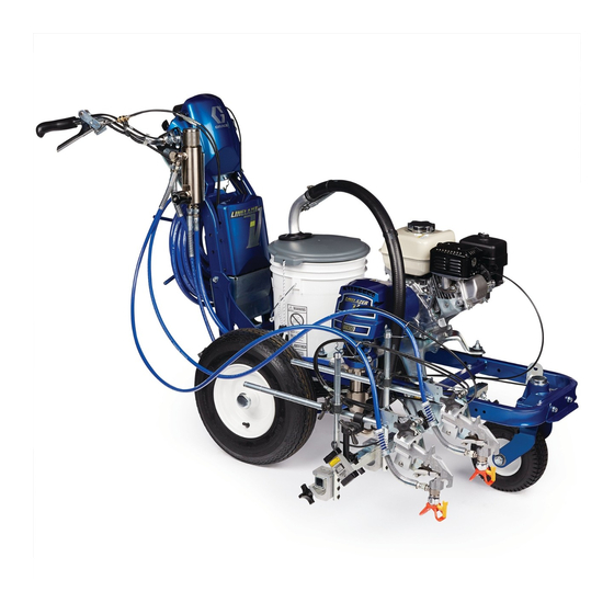
LineLazert III 3900 and 5900
Airless Paint Stripers
3300 psi (228 bar, 22.8 MPa) Maximum Working Pressure
LineLazer III 3900
Model
Series
233688
A
Striper with one Gun
233689
A
Striper with Second Gun Kit
233664
A
International Striper with one Gun
233694
A
International Striper with 2nd Gun Kit
LineLazer III 5900
Model
Series
233690
A
Striper with one Gun
233691
A
Striper with Second Gun Kit
233627
A
International Striper with one Gun
233695
A
International Striper with 2nd Gun Kit
Important Safety Instructions
Read all warnings and instructions in this manual.
Save these instructions.
. . . . . . . . . . . . . . . . . . . . . . . . . . . . . . . . . . .
. . . . . . . . . . . . . . . . . . . . . . . . . . . . . . . .
Repair
. . . . . . . . . . . . . . . . . . . . . . . . . . . . . . . .
. . . . . . . . . . . . . . . . . . . . . . . . . . . . . . . . . . . . .
. . . . . . . . . . . . . . . . . . . . . . . . . . . .
GRACO INC. P.O. BOX 1441 MINNEAPOLIS, MN 55440- -1441
ECOPYRIGHT 2002, GRACO INC.
Description
Description
Table of Contents
. . . . . . . . . . . . . . . . . . . . . . . . .
. . . . . . . . . . . . . . . . . . . . . . . .
. . . . . . . . . . . . .
Graco Inc. is registered to I.S. EN ISO 9001
Related Manuals
Operator
. . . . . . . . . . . . . . . . . . . . . . . . . . .
Displacement Pump
Spray Gun
Spray Tip
. . . . . . . . . . . . . . . . . . . . . . . . . . . . . . . . .
PC Board
Drain Valve Kit
Clutch Replacement Kit
* for spray tip selection, see page 4
2
Displacement Pump
Pinion and Drive Housing Assemblies
3
4
5
Pressure Control
8
. . . . . . . . . . . . . . . . . . . . . . . . . . . . . . . . . . .
. . . . . . . . . . . . . . . . . . . . . . . . . . . . . . . .
9
10
Graco Warranty
13
309414J
233688
. . . . . . . . . . . . . . . . .
. . . . . . . . . . . . . . . . . . . . . . . . .
. . . . . . . . . . . . . . . . . . . . . . . . . .
. . . . . . . . . . . . . . . . . . . . . .
. . . . . . . . . . . . . .
. . . . . . . . . . . . . . . . . . . . . . . . .
. . . . . . . . . . . . . . . . . . . . . .
. . . . . . . . . . . . . . . . . . . . . . . . . . . .
. . . . . . . . . . . . . . . . . . . . . . . . . .
. . . . . . . . . . . . . . . . . . . . . . . . . . . . . . .
ENG
ti1935a
309413
309277
309093
*
309459
308961
309890
15
. . . . . . . . . .
16
18
24
29
29
29
30
Advertisement
Table of Contents

Related Manuals for Graco LineLazert III 3900


Summary of Contents for Graco LineLazert III 3900
-
Page 1: Table Of Contents
......GRACO INC. P.O. BOX 1441 MINNEAPOLIS, MN 55440- -1441 ECOPYRIGHT 2002, GRACO INC. -
Page 2: Warnings And Cautions
Warnings and Cautions Warning Symbol Caution Symbol WARNING CAUTION This symbol alerts you to the possibility of serious This symbol alerts you to the possibility of damage to injury or death if you do not follow the instructions. or destruction of equipment if you do not follow the instructions. -
Page 3: Spray Tip Selection Table
Spray Tip Selection Table LineLazer Tip Selection Guide. Sprayer is supplied with tip LL5319. For additional applications, use the tip selec- tion table as follows: Note: the last three digits (LL5319) of the tip part number identifies the line width and tip orifice (opening). For example: the line width for tip LL5319 is 4 in. -
Page 4: Maintenance
Maintenance DAILY: Check pressure drain valve for proper opera- WARNING tion. INJECTION HAZARD DAILY: Check and fill the gas tank. The system pressure must be manually relieved to prevent the system from AFTER THE FIRST 20 HOURS OF OPERATION: starting or spraying accidentally. Fluid Drain engine oil and refill with clean oil. -
Page 5: Troubleshooting
0.2Ω (Line- ± ± Lazer III 5900); if not, replace pinion housing. Have pressure control checked by authorized Graco dealer. Clutch is worn, damaged, or incorrectly Replace clutch. Manual 309890. positioned Pinion assembly is worn or damaged Repair or replace pinion assembly. Manual 309890. - Page 6 Troubleshooting PROBLEM CAUSE SOLUTION Strainer (31) is clogged Clean strainer. Sprayer 233716 strainer is for Pump output is low use in paint only. Piston ball (206) is not seating Service piston ball. Manual 309277. Piston packings are worn or damaged Replace packings.
- Page 7 Troubleshooting PROBLEM CAUSE SOLUTION Gallon counter not working Broken or disconnected wire Check wires and connections. Replace broken wires. Bad sensor Replace sensor Missing magnet Replace magnet. Locate in correct spot. Sprayer operates, but display does not Bad connection between control board Remove display and reconnect and display Display damaged...
-
Page 8: Bearing Housing & Connecting Rod
Bearing Housing and Connecting Rod Removal 3. Clean mating surfaces of bearing and drive hous- ings. Relieve pressure; page 4. 4. Align connecting rod with crank (B) and carefully align locating pins (F) in drive housing (101) with holes in bearing housing (94). Push bearing hous- 2. -
Page 9: Drive Housing
Drive Housing Removal Installation 1. Liberally apply bearing grease (supplied with replacement gear cluster) to gear cluster (99) and Relieve pressure; page 4. to areas called out by note 3. Use full 0.62 pint (0.29 liter) of grease for LineLazer III 3900 and 0.68 pint (0.32 liter) of grease for LineLazer III 2. -
Page 10: Engine
Engine Removal 1. Remove Pinion Assembly/Rotor/Field/Pinion/ Clutch, Clamp and Clutch Housing, as in- structed in Manual 309890. 2. Fig. 4. Disconnect all necessary wiring. 3. Fig. 5. Remove two locknuts (72) and screws (131) from base of engine. 4. Lift engine carefully and place on work bench. NOTE: All service to the engine must be performed by an authorized HONDA dealer. - Page 11 On/Off Switch Removal Installation 1. Install new ON/OFF switch (24) so tabs of switch Relieve pressure; page 4. snap into place on inside of pressure control housing. 2. Fig. 6. Remove four screws (93) and display/cover (139). 2. Connect ON/OFF switch connector (B) to PC board.
- Page 12 Trigger Sensor Adjustment Refer to Troubleshooting for trigger sensor adjust- ment, and Manual 309413. Distance Sensor Adjustment Gear Alignment 5. Install wheel (82) on LineLazer. 6. Install nut (62) until tight, then back off 1/4 turn. Install dust cap (74) on wheel. Relieve pressure;...
-
Page 13: Pressure Control
Pressure Control Control Board Removal Installation When installing replacement control board, follow instructions with control board to set model type. Relieve pressure; page 4. 1. Fig. 6. Install control board (109) and jam nuts (Z). 2. Fig. 6. Remove four screws (93) and Install two connectors (Y) at backside of pressure display/cover (139). - Page 14 Control Board Diagnostics Digital Display Messages Relieve pressure before repair; page 4. No display does not mean that sprayer is not pressurized. DISPLAY SPRAYER INDICATION ACTION OPERATION No Display Sprayer may be pressurized. Loss of power or display Check power source. Relieve not connected pressure before repair or dis- assembly.
- Page 15 1. Fig. 11. Pull piston rod out 1.5 in. Screw in pump until holes in bearing cross link and piston rod Fig. 12 7673B align. Fig. 13. Fill packing nut with Graco TSL until fluid flows onto the top of seal. 1.5 in. Fig. 13 Fig. 11...
- Page 16 Parts - - Pinion and Drive Housing Assemblies Ref No. 183 and 101 Ref No. 183: Pinion Housing Assembly 245715 for Ref No. 101: Drive Housing Assembly 245442 for LineLazer III 3900; Pinion Housing Assembly LineLazer III 3900; Drive Housing Assembly 245443 245834 for LineLazer 5900 for LineLazer III 5900 Part No.
-
Page 17: Parts
Parts - - LineLazer III Parts Page 26 Parts Page 20 Parts Page 24 Parts Page 22 Parts Page 18 Parts Page 24 Sheet 1 of 6 ti1954a 309414... - Page 18 Parts - - LineLazer III Models 233688 and 233690 Sheet 2 of 6 ti1938a 309414...
- Page 19 Parts - - LineLazer III Ref. Ref. Part No. Description Qty. Part No. Description Qty. 196176 ADAPTER, nipple 101566 NUT, lock 114271 STRAP, retaining 114648 CAP, dust 114808 CAP, vinyl 186821 LABEL, warning 245798 HOSE, 1/4 in. X 7 ft 114690 STRAP 178342...
- Page 20 Parts - - LineLazer III Models 233688 and 233690 12 (see Detail E) Sheet 3 of 6 ti1942a 309414 Detail E (12)
- Page 21 Parts - - LineLazer III Ref. Ref. Part No. Description Qty. Part No. Description Qty. 196176 ADAPTER, nipple 176817 (3900) 245730 HOSE, suction and drain 183169 (5900) (includes 12a--12n) PIN, str, hdls 170957 TUBE, suction 176818 (3900) 185381 HOSE 183210 (5900) 110194 SWIVEL, 180_...
- Page 22 Parts - - LineLazer III Models 233688 and 233690 Ref. 166 164n 164m 164k 164w 164j 164v 164a 164x Ref. 166 Ref. 167 164j 164h 164f 164e 164d 164c 164g 164p Ref. 164 164u 164 (see Detail D) 164r 164b 164s 164t Detail D (164)
- Page 23 Parts - - LineLazer III Ref. Ref. Part No. Description Qty. Part No. Description Qty. 114682 SPRING, compression 164d 193662 PIN, locking, tapered 112405 NUT, lock 164e 110754 SCREW, cap, soc hd 100731 WASHER 164f 181818 KNOB, pronged 101566 NUT, lock 164g 114548 BEARING, bronze...
- Page 24 Parts - - LineLazer III Models 233688 and 233690 Ref. 182 Ref. 167 Ref. 13 30 (See Detail B) 115,118 Detail B (30) Ref. 204 Ref. 46 ti1939a Ref. 42 Ref. 182 To Display Sensor Sheet 5 of 6 309414...
- Page 25 Parts - - LineLazer III Ref. Ref. Part No. Description Qty. Part No. Description Qty. 100021 SCREW, cap hex hd 111017 BEARING, flange 100016 WASHER, lock 186699 BLOCK, mounting, cable 243284 GUN, flex, basic 181734 ARM, support Manual 309093 114029 CLAMP, swivel, adjustable 240780 BRACKET, arm, gun...
- Page 26 Parts - - LineLazer III Models 233688 and 233690 200 (See Detail A) Ref. 51 200a Ref.12j 200b Back View (42) 200c 200d 200r Ref. 42 Ref. 183 Ref. 58 200e 200p 200f 200g 200j 200h 200k 200m 200n Detail A (200) ti1941a 309414...
- Page 27 Parts - - LineLazer III Ref. Ref. Part No. Description Qty. Part No. Description Qty. 114955 CONTROL, throttle 196Y 15A245 LABEL, warning 114954 SWITCH, rocker 198Y 189246 LABEL, warning 109466 NUT, lock, hex 198684 SPACER, base 116167 KNOB, potentiometer 245515 FILTER, assembly 112380 SCREW, mach, pan hd...
- Page 28 Pressure Control Wiring Diagram Display Board ON/OFF Switch Drive Pinion Housing Housing Control Board Clutch Test Points Transducer View A View B 200p To Engine Potentiometer Trigger Sensor View A View B Engine Power Clutch Coil Gallon Distance Sensor Counting Thermistor Sensor ti1943a...
-
Page 29: Linelazer Iii 3900/5900
If you have painters who do not read En- glish, order one of the following labels to apply to your sprayer. The drawing shows the best place- ment of these labels for good visibility. Order the labels from your Graco distributor. French 194931 Spanish... -
Page 30: Graco Phone Number
Graco distributor to the original purchaser for use. With the exception of any special, extended, or limited warranty published by Graco, Graco will, for a period of twelve months from the date of sale, repair or replace any part of the equipment determined by Graco to be defective.