Table of Contents
Advertisement
Quick Links
Advertisement
Table of Contents

Related Manuals for National Instruments 9401


Summary of Contents for National Instruments 9401
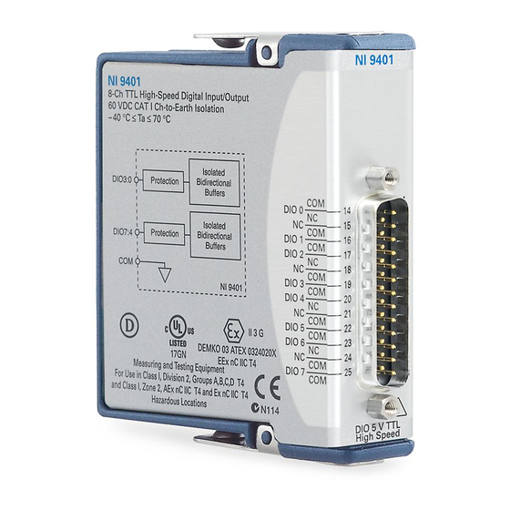
- Page 1 GETTING STARTED GUIDE NI 9401 8 DIO, 5 V/TTL, Bidirectional, 100 ns...
-
Page 2: Safety Guidelines
This document explains how to connect to the NI 9401. Before you begin, complete the software and Note hardware installation procedures in your chassis documentation. The guidelines in this document are specific to Note the NI 9401. The other components in the system might not meet the same safety ratings. -
Page 3: Safety Voltages
The maximum voltage that can be applied or output between any channel and COM without damaging the module or other devices. NI 9401 Getting Started Guide | © National Instruments | 3... -
Page 4: Safety Guidelines For Hazardous Locations
CAT III, or CAT IV. Safety Guidelines for Hazardous Locations The NI 9401 is suitable for use in Class I, Division 2, Groups A, B, C, D, T4 hazardous locations; Class I, Zone 2, AEx nA IIC T4 and Ex nA IIC T4 hazardous locations; and nonhazardous locations only. -
Page 5: Special Conditions For Hazardous Locations Use In Europe And Internationally
Special Conditions for Hazardous Locations Use in Europe and Internationally The NI 9401 has been evaluated as Ex nA IIC T4 Gc equipment under DEMKO Certificate No. 03 ATEX 0324020X and is IECEx UL 14.0089X certified. Each NI 9401 is marked II 3G NI 9401 Getting Started Guide | ©... -
Page 6: Electromagnetic Compatibility Guidelines
Zone 2 hazardous locations, in ambient temperatures of -40 °C ≤ Ta ≤ 70 °C. If you are using the NI 9401 in Gas Group IIC hazardous locations, you must use the device in an NI chassis that has been evaluated as Ex nC IIC T4, Ex IIC T4, Ex nA IIC T4, or Ex nL IIC T4 equipment. - Page 7 To ensure the specified EMC performance, Caution you must install a clamp-on ferrite bead (782803-01) in accordance with the product installation instructions. NI 9401 Getting Started Guide | © National Instruments | 7...
-
Page 8: Cable Requirements For Emc Compliance
Cable Requirements for EMC Compliance Select and install cables for the NI 9401 in accordance with the following requirements: • Install a clamp-on ferrite bead (782803-01) on the cable that you are connecting to NI 9401. • The clamp-on ferrite bead must be connected to the cable as close to the module as possible. -
Page 9: Special Conditions For Marine Applications
(shipboard) applications. To verify Lloyd’s Register certification for a product, visit ni.com/certification and search for the LR certificate, or look for the Lloyd’s Register mark on the product. NI 9401 Getting Started Guide | © National Instruments | 9... -
Page 10: Preparing The Environment
EMC performance is attained. Preparing the Environment Ensure that the environment in which you are using the NI 9401 meets the following specifications. Operating temperature -40 °C to 70 °C... - Page 11 Connecting the NI 9401 The NI 9401 provides connections for 8 digital input/output channels. NI 9401 Getting Started Guide | © National Instruments | 11...
- Page 12 Figure 2. NI 9401 Pinout DIO0 DIO1 DIO2 DIO3 DIO4 DIO5 DIO6 DIO7 12 | ni.com | NI 9401 Getting Started Guide...
- Page 13 Note that all four channels in the port must share the same line direction. Connecting a Serial Peripheral Interface Device You can connect a Serial Peripheral Interface (SPI) device to the NI 9401. NI 9401 Getting Started Guide | © National Instruments | 13...
-
Page 14: Connecting Digital Devices
DIO1 Configured MOSI DIO2 for Output MISO DIO4 DIO7:4 Configured for Input SPI Device NI 9401 Connecting Digital Devices You can connect several types of digital devices to the NI 9401. 14 | ni.com | NI 9401 Getting Started Guide... - Page 15 The overcurrent protection allows only a specified amount of current through the output channels to protect the NI 9401 from short circuits. If the NI 9401 goes into an overcurrent state, the NI 9401 Getting Started Guide | © National Instruments | 15...
- Page 16 DIO channels to high impedance for approximately 280 ms. When the channels are in an overcurrent state, the NI 9401 can accept new line direction configuration and output state data but cannot pass valid input data to the software.
-
Page 17: Where To Go Next
NI 9401 Datasheet NI-RIO Help NI-DAQmx Help LabVIEW FPGA Help LabVIEW Help RELATED INFORMATION C Series Documentation Services & Resources ni.com/services ni.com/info cseriesdoc Located at ni.com/manuals Installs with the software NI 9401 Getting Started Guide | © National Instruments | 17... -
Page 18: Worldwide Support And Services
(EMC) and product safety. You can obtain the DoC for your product by visiting ni.com/certification. If your product supports calibration, you can obtain the calibration certificate for your product at ni.com/calibration. 18 | ni.com | NI 9401 Getting Started Guide... - Page 19 United States, visit the Worldwide Offices section of ni.com/niglobal to access the branch office websites, which provide up-to-date contact information, support phone numbers, email addresses, and current events. NI 9401 Getting Started Guide | © National Instruments | 19...
- Page 20 U.S. Government Customers: The data contained in this manual was developed at private expense and is subject to the applicable limited rights and restricted data rights as set forth in FAR 52.227-14, DFAR 252.227-7014, and DFAR 252.227-7015. © 2005—2015 National Instruments. All rights reserved. 374068G-01 Dec15...