Toro Groundsmaster 4300-D Operator's Manual
Traction unit
Hide thumbs
Also See for Groundsmaster 4300-D:
- Service manual (399 pages) ,
- Operator's manual (72 pages) ,
- Operator's manual (40 pages)

Related Manuals for Toro Groundsmaster 4300-D


Summary of Contents for Toro Groundsmaster 4300-D
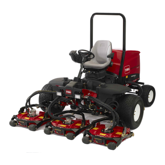
- Page 1 Form No. 3428-937 Rev B Groundsmaster ® 4300-D Traction Unit Model No. 30864—Serial No. 403430001 and Up *3428-937* B Register at www.Toro.com. Original Instructions (EN)
- Page 2 Section 4442 or 4443 to use or operate the engine on additional information, contact an Authorized Service any forest-covered, brush-covered, or grass-covered Dealer or Toro Customer Service and have the model land unless the engine is equipped with a spark and serial numbers of your product ready.
-
Page 3: Table Of Contents
Contents Pre-Maintenance Procedures ......53 Raising the Machine ......... 53 Lubrication ............53 Safety ............... 4 Greasing the Bearings and Bushings ....53 General Safety ........... 4 Engine Maintenance ........... 55 Engine Emission Certification ......4 Engine Safety ........... 55 Safety and Instructional Decals ...... -
Page 4: Safety
Safety This machine has been designed in accordance with EN ISO 5395 (when you complete the setup procedures) and ANSI B71.4-2017. General Safety This product is capable of amputating hands and feet and of throwing objects. Always follow all safety instructions to avoid serious personal injury. -
Page 5: Safety And Instructional Decals
Safety and Instructional Decals Safety decals and instructions are easily visible to the operator and are located near any area of potential danger. Replace any decal that is damaged or missing. decal93-6681 93-6681 1. Cutting/dismemberment hazard, fan—stay away from moving parts. decal106-6755 106-6755 1. - Page 6 decal120-4158 120-4158 1. Read the Operator’s 3. Engine—preheat Manual. 2. Engine—start 4. Engine—shut off decal117-0169 117-0169 1. Read the Operator's Manual. 2. Power point (10 A) 3. Head lights (10 A) 4. Power (10 A) decalbatterysymbols Battery Symbols 5. Engine start (15 A) Some or all of these symbols are on your battery 6.
- Page 7 decal125-8754 125-8754 1. Head lights 6. Slow 2. Engage 7. Lower the cutting units 3. Power take-off (PTO) 8. Raise the cutting units 4. Disengage 9. Read the Operator’s Manual. 5. Fast decal121-3627 121-3627 1. Height-of-cut settings...
- Page 8 decal133-2930 133-2930 1. Warning—do not operate this machine unless you are trained. 4. Tipping hazard—drive slowly when turning; do not turn sharply while traveling fast; only drive on slopes with the cutting units lowered; always wear a seatbelt. 2. Warning—wear hearing protection. 5.
- Page 9 decal138-6975 138-6975 1. Read the Operator's Manual.
-
Page 10: Setup
Setup Loose Parts Use the chart below to verify that all parts have been shipped. Procedure Description Qty. Warning decal Install the decals (CE Machines Only). CE decal – No parts required Adjust the control arm position. – No parts required Remove shipping blocks and pins. -
Page 11: Adjusting The Control Arm Position
Installing the Decals (CE Adjusting the Control Arm Machines Only) Position Parts needed for this procedure: No Parts Required Warning decal Procedure CE decal You can adjust the control arm position for your comfort. Procedure Loosen the 2 bolts securing the control arm to •... -
Page 12: Removing The Shipping Blocks And Pins
Rear weights (quantity varies with configuration). Procedure The Groundsmaster 4300-D Traction Unit complies with EN ISO 5395 and ANSI B71.4-2017 standards when equipped with rear weights and/or 40.8 kg (90 lb) of calcium chloride ballast that is added to the rear wheels. -
Page 13: Installing The Hood Latch
g194425 g031632 Figure 5 Installing the Hood Latch For CE Compliance Parts needed for this procedure: Hood-latch assembly Washer Procedure g004143 Figure 6 Unlatch and raise the hood. 1. Rubber grommet Remove the rubber grommet from the hole in the left side of the hood (Figure Remove the nut from the hood-latch assembly (Figure... -
Page 14: Adjusting The Carrier Frame
g003946 Figure 7 1. Nut 3. Hood latch 2. Metal washer 4. Rubber washer g011343 Figure 8 On the outside of the hood, insert the hook end of the latch through the hole in the hood and 1. Front-cutting-unit 3. Rear-cutting-unit mounting ensure that the rubber-sealing washer remains mounting hole (upper) hole... -
Page 15: Adjusting The Roller Scraper
Optional No Parts Required Adjusting the Roller Procedure Scraper Contact your authorized Toro distributor for the correct mulching baffle. Optional Thoroughly clean debris from the mounting holes on the rear wall and left wall of the chamber. Install the mulching baffle in the rear opening... -
Page 16: Adjusting The Machine Software
Adjusting the Machine Software No Parts Required Procedure Contact your authorized Toro distributor to set the machine software to the CE mode. Preparing the Machine No Parts Required Checking the Tire Pressure Check the tire pressure before use; refer to... -
Page 17: Product Overview
Brake Pedal Product Overview Press the brake pedal (Figure 11) to stop the machine. Controls Parking Brake Traction Pedal To engage the parking brake, (Figure 11) push down the brake pedal and press the top forward to latch. To The traction pedal (Figure 11) controls the forward and disengage the parking brake, press the brake pedal... - Page 18 g021208 g031683 Figure 12 Figure 13 1. Lower mow/raise control 4. Enable/disable switch 1. Hydraulic-filter-restriction indicator lever 2. Key switch 5. Engine-speed switch 3. InfoCenter 6. Headlight switch Power Point The power point (Figure 14) is a 12 V power supply Key Switch for electronic devices.
- Page 19 • Middle Button—use this button to scroll down menus. • Right Button—use this button to open a menu where a right arrow indicates additional content. • Beeper—activated when lowering the cutting units or for advisories and faults. Note: The purpose of each button may change depending on what is required at the time.
- Page 20 InfoCenter Icon Description InfoCenter Icon Description (cont'd.) SERVICE DUE Indicates when scheduled service should be performed The cruise control is on. Hours remaining until service Reset the service hours Shut off the engine The status of the engine speed (rpm) Engine Info icon Key switch...
- Page 21 NOx control diagnosis malfunction; drive the machine back to the shop Service—Menu Item Description and contact your authorized Toro Hours Lists the total number of hours distributor (software version U and that the machine, engine, and later).
- Page 22 0000 or 1234. Language Controls the language used If you changed the PIN code and forgot the code, on the InfoCenter* contact your authorized Toro distributor for assistance. LCD Backlight Controls the brightness of the LCD display From the M...
- Page 23 Viewing and Changing the Protected Menu Settings In the Protected Menu, scroll down to Protect Settings. To view and change the settings without entering a PIN code , use the right button to change the Protect Settings to O To view and change the settings with a PIN code, use the left button to change the Protect Settings to O , set the PIN code, and turn the...
-
Page 24: Specifications
Specifications Note: Specifications and design are subject to change without notice. g193881 Figure 19... -
Page 25: Cutting Unit Specifications
88 kg (195 lb) Attachments/Accessories A selection of Toro approved attachments and accessories is available for use with the machine to enhance and expand its capabilities. Contact your Authorized Service Dealer or authorized Toro distributor or go to www.Toro.com for a list of all approved attachments and accessories. -
Page 26: Before Operation
Filling the Fuel Tank Operation Note: Determine the left and right sides of the Fuel Tank Capacity machine from the normal operating position. 53 L (14 US gallons) Before Operation Fuel Specification Before Operation Safety Important: Use only ultra-low sulphur diesel fuel. - Page 27 Monitor seals, hoses, gaskets in contact with fuel as they may be degraded over time. • Fuel filter plugging may be expected for a time after converting to biodiesel blends. • Contact your authorized Toro distributor for more information on biodiesel.
-
Page 28: Checking The Engine-Oil Level
Checking the Engine-Oil Level Before you start the engine and use the machine, check the oil level in the engine crankcase; refer to Checking the Engine-Oil Level (page 56). Checking the Cooling System g001055 Before you start the engine and use the machine, Figure 21 check the cooling system;... -
Page 29: Adjusting The Height Of Cut
Adjusting the Height of Cut Position the tapped plate in-line with the spacer. Install the bolt finger-tight. Important: The cutting units often cut Repeat steps through for each side approximately 6 mm (1/4 inch) lower than a reel adjustment. cutting unit with the same bench setting. It may be necessary to set the cutting-unit bench Torque all 3 bolts to 41 N∙m (30 ft-lb). -
Page 30: Checking The Safety-Interlock Switches
These switches disengage either the traction the braking valve needs adjustment. Call your or the PTO whenever you leave the seat. Although authorized Toro distributor for assistance in the engine continues to run if you disengage the PTO making this adjustment. -
Page 31: Understanding The Diagnostic Light
Attributes: • Discharge remains more even at lower heights of cut. • Discharge has less tendency to throw left and thus a cleaner look around bunkers and fairways. • Lower power requirement at lower heights and dense turf. High-Lift Parallel Sail (Not CE Compliant) The blade generally performs better in the higher g021272... -
Page 32: Choosing Accessories
Choosing Accessories Optional Equipment Configurations Angle Sail Blade High-Lift, Parallel-Sail Mulching Baffle Roller Scraper Blade (Do not use with the mulching baffle) (Not CE Compliant) Grass Cutting: 1.9 to 4.4 Recommended in most May work well in light or Has been shown to Use it whenever the applications sparse turf... -
Page 33: During Operation
• Use accessories, attachments, and replacement • Use your full attention while operating the parts approved by Toro only. machine. Do not engage in any activity that causes distractions; otherwise, injury or property damage may occur. Rollover Protection System •... -
Page 34: Starting The Engine
Slope Safety Starting the Engine • Slopes are a major factor related to loss of control Important: The fuel system automatically bleeds and rollover accidents, which can result in severe itself before starting the engine if you are starting injury or death. You are responsible for safe slope the engine for the first time, the engine has shut operation. -
Page 35: Diesel Particulate Filter Regeneration
• When the cutting units are over the far edge of If the back pressure in the DPF is too high or a the mowing area, lift the cutting units. reset regeneration has not occurred for 100 hours, the engine computer signals you through the Perform a tear-shaped turn to quickly line up for InfoCenter when reset regeneration is running. - Page 36 DPF Ash Accumulation • When enough ash accumulates, the engine computer sends information to the InfoCenter • The lighter ash is discharged through the exhaust in the form of an engine fault to indicate the system; the heavier ash collects in the soot filter. accumulation of ash in the DPF.
- Page 37 Types of Diesel Particulate Filter Regeneration Types of diesel particulate filter regeneration that are performed while the machine is operating: Type of Regeneration Conditions that cause DPF regeneration DPF description of operation Passive Occurs during normal operation of the machine at •...
- Page 38 Types of diesel particulate filter regeneration that require you to park the machine: (cont'd.) Type of Regeneration Conditions that cause DPF regeneration DPF description of operation Recovery Occurs because the operator ignored requests for • When the reset-standby/parked or recovery a parked regeneration and continued operating the machine, adding more soot to the DPF regeneration icon...
- Page 39 press the right button to select the Technician entry DPF Operation Table (cont'd.) (Figure 31). State Description Reset Regen The engine computer is running a reset regeneration. The engine computer is requesting that Parked Stby you run a parked regeneration. Parked Regen You initiated a parked regeneration request and the engine computer is...
- Page 40 Assist DPF Regeneration • The icon displays in the InfoCenter while the reset regeneration is processing. • The engine computer adjusts engine settings to • Whenever possible, do not shut off the engine or raise the exhaust temperature. reduce engine speed while the reset regeneration •...
- Page 41 g227304 g224394 Figure 36 Figure 38 Press the right button to change the inhibit Note: If the InfoCenter displays A #186 DVISORY regeneration setting from On to Off (Figure (Figure 39), set the engine to full throttle (high idle) to or from Off to On (Figure 37).
- Page 42 Parked or Recovery Regeneration regeneration required—power takeoff disabled #189 (Figure 43). DVISORY • When the engine computer requests either a parked regeneration or a recovery regeneration, the regeneration request icon (Figure 40) displays in the InfoCenter. g224398 Figure 43 Important: Perform a parked regeneration to restore the PTO function;...
- Page 43 Preparing to Perform a Parked or Recovery Regeneration Ensure that the machine has fuel in the tank for the type of regeneration you are performing: • Parked Regeneration: Ensure that you g224399 Figure 47 have 1/4 tank of fuel before performing the parked regeneration.
- Page 44 At the DPF checklist screen, verify that the parking brake is engaged and that the engine speed is set to low idle (Figure 52). g224402 g224407 g224629 Figure 50 At the V screen, verify that you g227679 ERIFY FUEL LEVEL Figure 52 have 1/4 tank of fuel if you are performing the parked regeneration or 1/2 tank of fuel if you are...
- Page 45 If the machine is requesting a regeneration and appears in the lower right corner of the screen this message appears contact your authorized as the regeneration processes. Toro distributor for service. Check Message and Corrective Action Table Corrective Action: Exit the regeneration menu and run the g224403...
- Page 46 Note: Canceling a Parked or Recovery Regeneration While the DPF regeneration runs, the InfoCenter displays the high Use the Parked Regen Cancel or Recovery Regen Cancel setting to cancel a running parked or recovery exhaust-temperature icon regeneration process. When the engine computer completes a Access the DPF Regeneration menu (Figure parked or recovery regeneration, the InfoCenter...
-
Page 47: Operating Tips
Operating Tips build up in mower housing, cutting performance will decrease. Becoming Familiarized with the Transporting the Machine Between Machine Jobs Before mowing grass, practice operating the machine Move the Enable/Disable switch to the D in an open area. Start and shut off the engine. ISABLE position and raise the cutting units to the T RANSPORT... -
Page 48: After Operation
After Operation General Safety • Shut off the engine, remove the key (if equipped), and wait for all movement to stop before you leave the operator’s position, Allow the machine to cool before adjusting, servicing, cleaning, or storing it. • Clean grass and debris from the cutting units, mufflers, and engine compartment to help prevent fires. -
Page 49: Pushing Or Towing The Machine
Pushing or Towing the Machine In an emergency, you can move the machine forward by actuating the bypass valve in the variable-displacement hydraulic pump and pushing or towing the machine. Important: Do not push or tow the machine faster than 3 to 4.8 km/h (2 to 3 mph). If you push or tow at a faster speed, internal transmission damage may occur. -
Page 50: Maintenance
Allow machine components to cool before • To ensure safe, optimal performance of the performing maintenance. machine, use only genuine Toro replacement • If the cutting units are in the transport position, use parts. Replacement parts made by other the positive mechanical lock (if equipped) before manufacturers could be dangerous, and such use you leave the machine unattended. - Page 51 Maintenance Service Maintenance Procedure Interval • Service the air cleaner. (Or earlier if the air-cleaner indicator illuminates red. Service it more frequently in extremely dirty or dusty conditions.) • Replace the fuel filter. Every 400 hours • Inspect the fuel lines and connections. •...
-
Page 52: Daily Maintenance Checklist
Date Information Important: Refer to your engine owner's manual for additional maintenance procedures. Note: Download a free copy of the electrical or hydraulic schematic by visiting www.Toro.com and searching for your machine from the Manuals link on the home page. -
Page 53: Pre-Maintenance Procedures
Pre-Maintenance Lubrication Procedures Greasing the Bearings and Bushings Raising the Machine If you operate the machine under normal conditions, Use the following as points to jack up the machine: use No. 2 lithium grease to lubricate all bearings • Front of the machine—rectangular pad, under and bushings at the specified maintenance interval. - Page 54 • • Cutting unit carrier-frame pivot (1 each)—Figure Axle-steering pivot (1)—Figure 70 g004169 Figure 70 • Steering-cylinder ball joints (2) and rear axle g011613 (1)—Figure 71 Figure 67 • Lift-arm pivot shaft (1 each)—Figure 68 g004157 Figure 68 • Rear axle tie rod (2)—Figure 69 g011614 Figure 71...
-
Page 55: Engine Maintenance
Engine Maintenance • Cutting unit spindle-shaft bearings (2 per cutting unit)—Figure 73 Note: You can use either fitting, whichever is Engine Safety more accessible. Pump grease into the fitting until a small amount appears at bottom of the spindle • Shut off the engine and remove the key before housing (under the cutting unit). -
Page 56: Servicing The Engine Oil
Servicing the Engine Oil Oil Specification Toro Premium Engine Oil is available from your authorized Toro distributor in either 15W-40 or 10W-30 viscosity grades. g194209 Use high-quality, low-ash engine oil that meets or exceeds the following specifications: • API service category CJ-4 or higher •... - Page 57 g194204 g194203 g031256 Figure 76 g031400 Note: When using different oil, drain all old oil Figure 77 from the crankcase before adding new oil. Add oil to the crankcase. Crankcase Oil Capacity Approximately 5.2 L (5.5 US qt) with the filter. Changing the Engine Oil and Filter Service Interval: After the first 50 hours Every 250 hours...
-
Page 58: Fuel System Maintenance
Fuel System entering the fuel system. Remove the fuel-pickup tube and clean screen as required. Maintenance Servicing the Fuel Filter Service Interval: Every 400 hours—Replace the fuel filter. Clean the area around the fuel-filter head (Figure 78). g021576 Figure 78 1. -
Page 59: Servicing The Water Separator
Servicing the Water Separator Service Interval: Every 400 hours—Replace the fuel filter canister. Before each use or daily—Drain water or other contaminants from the water separator. After replacing the water separator, turn the key to g194210 but do not start the engine 3 times for 10 seconds each time. -
Page 60: Servicing The Diesel-Oxidation Catalyst (Doc) And The Soot Filter
Manual for information on disassembling and assembling the diesel-oxidation catalyst and the Locating the Fuses soot filter of the DPF. Refer to your authorized Toro distributor for There are 8 fuses in the electrical system. The diesel-oxidation catalyst and the soot filter fuse block... -
Page 61: Charging The Battery
Charging the Battery WARNING Charging the battery produces gasses that can explode. Do not smoke near the battery, and keep sparks and flames away from the battery. Important: Keep the battery fully charged. This is especially important to prevent battery damage when the temperature is below 0°C (32°F). -
Page 62: Drive System Maintenance
Drive System Turn the key in the switch to the O position, start the engine, and rotate the cam hex in either Maintenance direction until the wheels cease rotation. Tighten the locknut to secure the adjustment. Turn the key in the switch to the O position, Adjusting the Traction remove the jack stands, and lower the machine... -
Page 63: Cooling System Maintenance
Cooling System Maintenance Cooling System Safety • Swallowing engine coolant can cause poisoning; keep out of reach from children and pets. • Discharge of hot, pressurized coolant or touching a hot radiator and surrounding parts can cause severe burns. – Always allow the engine to cool at least 15 g021866 minutes before removing the radiator cap. -
Page 64: Brake Maintenance
Brake Maintenance Adjusting the Parking Brakes Adjust the brakes when there is more than 2.5 cm (1 inch) of free travel (Figure 89) of the brake pedal, or when more holding force is required. Free travel is the distance the brake pedal moves before you feel braking resistance. -
Page 65: Adjusting The Parking-Brake Latch
Belt Maintenance that the cable conduit does not rotate during tightening procedure. Servicing the Alternator Adjusting the Belt Parking-Brake Latch Service Interval: After the first 10 hours If the parking brake fails to engage and latch, an Every 100 hours adjustment to the brake pawl is required. -
Page 66: Hydraulic System Maintenance
Toro. This fluid is compatible with the elastomers used Fluid in Toro hydraulic systems and is suitable for a wide-range of temperature conditions. This fluid is compatible with conventional mineral oils, but for Hydraulic Fluid Specifications... - Page 67 Hydraulic Fluid Capacity: 56.7 L (15 US gallons) If fluid becomes contaminated, contact your Toro Distributor because the system must be flushed. Contaminated fluid looks milky or black when compared to clean oil. Turn the key in the switch to the O position and raise the hood.
- Page 68 Replacing the Hydraulic Filters Service Interval: Every 1,000 hours—If you are using the recommended hydraulic fluid, replace the hydraulic filter (sooner if the service interval indicator is in the red zone). g031625 Every 800 hours—If you are not using the recommended hydraulic fluid or have ever filled the reservoir with an alternative fluid, replace the hydraulic filter (sooner if the service...
-
Page 69: Checking The Hydraulic Lines And Hoses
Testing the Hydraulic-System Pressure Use the hydraulic system test ports to test the pressure in the hydraulic circuits. Contact your authorized Toro distributor for assistance. Hydraulic Valve Solenoid Functions Use the list below to identify and describe the different g031691 Figure 98 functions of the solenoids in the hydraulic manifold. -
Page 70: Mounting The Cutting Units To The Traction Unit
Mounting the Cutting Units Assembling the Front Roller Press the first bearing into the roller housing to the Traction Unit (Figure 99). Press on the outer race only or equally on the inner and outer race. Position the machine on a level surface and turn the key in the switch to the O position. -
Page 71: Blade Maintenance
Blade Maintenance Compare the 12 o’clock measured height to the height-of-cut setting. It should be within 0.7 mm (0.030 inch). The 3 and 9 o’clock heights should Blade Safety be 1.6 to 6.0 mm (0.06 to 0.24 inch) higher than the 12 o’clock setting and within 1.6 to 6.0 mm •... -
Page 72: Removing And Installing The Cutting-Unit Blade(S)
1 through 3. Replace the blade if it hits a solid object, is out of balance, or is bent. Always use genuine Toro Secure the carriage bolts and flange nuts. replacement blades to ensure safety and optimum Again, verify the 12, 3, and 9 o’clock heights. -
Page 73: Inspecting And Sharpening The Blade
Inspecting and Sharpening If dull or nicked, sharpen only the top cutting edge while maintaining the original cutting angle the Blade (Figure 104). Note: Raise the cutting deck to the transport position, The blade will remain balanced if the same amount of metal is removed from both turn the key in the ignition switch to the O cutting edges. -
Page 74: Storage
Storage Remove and discard the oil filter. Install a new oil filter. Refill the oil pan with designated quantity of Storage Safety motor oil. • Shut off the engine, remove the key (if equipped), Turn the key in the switch to the O position, and wait for all movement to stop before you leave start the engine, and run it at idle speed for... - Page 75 Notes:...
- Page 76 Notes:...
- Page 77 Notes:...
- Page 78 The Way Toro Uses Information Toro may use your personal information to process warranty claims, to contact you in the event of a product recall and for any other purpose which we tell you about. Toro may share your information with Toro's affiliates, dealers or other business partners in connection with any of these activities. We will not sell your personal information to any other company.
- Page 79 While the exposure from Toro products may be negligible or well within the “no significant risk” range, out of an abundance of caution, Toro has elected to provide the Prop 65 warnings. Moreover, if Toro does not provide these warnings, it could be sued by the State of California or by private parties seeking to enforce Prop 65 and subject to substantial penalties.
- Page 80 Countries Other than the United States or Canada Customers who have purchased Toro products exported from the United States or Canada should contact their Toro Distributor (Dealer) to obtain guarantee policies for your country, province, or state. If for any reason you are dissatisfied with your Distributor's service or have difficulty obtaining guarantee information, contact your Authorized Toro Service Center.