Toro ProLine H800 Operator's Manual
Hide thumbs
Also See for ProLine H800:
- Service manual (343 pages) ,
- Setup instructions (8 pages) ,
- Installation instructions (4 pages)

Related Manuals for Toro ProLine H800


Summary of Contents for Toro ProLine H800
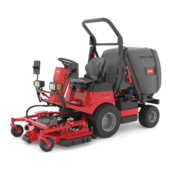
- Page 1 Form No. 3435-272 Rev B ProLine H800 Rotary Mower Model No. 31050—Serial No. 317000001 and Up Model No. 31050TE—Serial No. 319000001 and Up *3435-272* B Register at www.Toro.com. Original Instructions (EN)
- Page 2 Whenever you need service, genuine Toro parts, or more information, contact an Authorized Service Dealer or Toro Customer Service and have the model and serial numbers of your product ready. Figure 1 identifies the location of the model and serial numbers on the product.
-
Page 3: Table Of Contents
Contents Lubrication ............43 Greasing the Mower Deck ........ 43 Greasing the Bearings and Bushings ....44 Safety ............... 4 Lubricating the Driveshaft U-Joints ....47 General Safety ........... 4 Lubricating the Driveshaft Sliding Joints.... 48 Safety and Instructional Decals ......5 Engine Maintenance ........... -
Page 4: Safety
Safety Rotating the Mower Deck into the Mowing Position ............71 Servicing the Blades ......... 72 This machine has been designed in accordance with Disconnecting the Driveshaft from the ANSI B71.4-2017 (when you complete the setup Mower-Deck Gearbox ........75 procedures) and EN ISO 5395. -
Page 5: Safety And Instructional Decals
Safety and Instructional Decals Safety decals and instructions are easily visible to the operator and are located near any area of potential danger. Replace any decal that is damaged or missing. decalbatterysymbols Battery Symbols Some or all of these symbols are on your battery. 1. - Page 6 decal134-0546 134-0546 1. Read the Operator’s 2. Grease points Manual. decal134-0543 134-0543 1. Lower/float the deck 6. Close the hopper 2. Deck hold position 7. Dump the hopper 3. Raise the deck 8. Crushing of whole body from above hazard—ensure that there are no bystanders nearby before lowering the hopper.
- Page 7 decal134-0552 134-0552 1. Fast 2. Slow decal134-0549 134-0549 decal134-0553 134-0553 1. Height of cut 1. Warning—do not touch the 2. Stay away from moving hot surface. parts; keep all guards and shields in place. decal134-1357 134-1357 1. Read the Operator’s 3.
- Page 8 decal134-1358 134-1358 1. Attention—read the Operator’s Manual before performing maintenance; with the mower deck lowered, raise the hopper, remove the grass chute, and raise the deck. decal134-0540 134-0540 1. Thrown object 3. Cutting/dismemberment hazard—keep bystanders hazard of feet, mower away. blade—stay away from moving parts;...
- Page 9 Affix for non-CE machines decal125-6135 125–6135 Affix over Part No. 134-0539 for non-CE machines decal134-1986 134-1986 1. Warning—read the Operator’s Manual. 5. Thrown object hazard—keep bystanders away. 2. Warning—all operators should be trained before operating 6. Cutting/dismemberment hazard of hand or foot—stay away the machine.
- Page 10 decal134-0539 134-0539 Note: This machine complies with the industry standard stability test in the static lateral and longitudinal tests with the maximum recommended slope indicated on the decal. Review the instructions for operating the machine on slopes in the Operator’s Manual as well as the conditions in which you would operate the machine to determine whether you can operate the machine in the conditions on that day and at that site.
-
Page 11: Setup
Setup Media and Additional Parts Description Qty. Operator's Manual Review before operating the machine. Engine owner's manual Use to reference engine information. Declaration of Conformity Note: Determine the left and right sides of the machine from the normal operating position. Charging the Battery Checking the Air Pressure in the Tires... -
Page 12: Mounting The Mower Deck
Mounting the Mower Deck No Parts Required Procedure Remove the traction unit and mower deck from the shipping pallet. Install the mower deck to the traction unit; refer Installing the Mower Deck (page 76). -
Page 13: Product Overview
Product Overview g224574 Figure 4 1. Dash panel 6. Taillight 2. Steering wheel 7. Fuel tank 3. Roll bar 8. Skid 4. Rotating beacon 9. Caster wheel 5. Hopper... - Page 14 g224634 Figure 5 1. Hydraulic-reservoir cap 7. Height-of-cut (HOC) gauge 2. Radiator 8. Road light/turn signal light 3. Right console 9. Mirror 4. Key switch 10. Brake pedal 5. Traction pedal 11. Work light 6. Parking-brake lock 12. Left console...
-
Page 15: Controls
Controls Note: Determine the left and right sides of the machine from the normal operating position. Dash Panel g213936 Figure 6 1. Steering-column tilt lever 5. Air-filter restriction indicator 9. Parking-brake indicator 13. Radiator fan-reversal switch 2. Battery-charge indicator 6. Work-light indicator 10. - Page 16 O position, the machine automatically contact your authorized Toro distributor for assistance. shuts off the engine after a 1-second delay; refer to Check the operation of warning light as follows: Resetting the PTO Function (page 34).
- Page 17 Horn Button Fuel Gauge The fuel gauge (Figure 8) indicates the level of fuel Push the horn button inward to activate the horn remaining in the fuel tank. (Figure Brake Pedal Use the brake pedal (Figure 7) to stop or slow the machine.
- Page 18 Throttle Lever Use the throttle lever (Figure 8) to control the engine speed. Moving the throttle lever forward toward the position increases the engine speed. Moving the throttle lever rearward toward the S position decreases the engine speed. The throttle lever controls the speed of the blades and, with the traction pedal, controls the ground speed of the machine.
- Page 19 g214136 Figure 11 1. O position 3. O position REHEAT 2. L position 4. S position IGHTS TART...
-
Page 20: Specifications
Specifications Note: Specifications and design are subject to change without notice. g214888 Figure 12... -
Page 21: Attachments/Accessories
500 kg (1,102 lb) Attachments/Accessories A selection of Toro approved attachments and accessories is available for use with the machine to enhance and expand its capabilities. Contact your Authorized Service Dealer or authorized Toro distributor or go to www.Toro.com for a list of all approved attachments and accessories. -
Page 22: Before Operation
Performing Daily Operation Maintenance Before Operation Before starting the machine each day, perform the Each Use/Daily procedures listed in Daily Maintenance Checklist (page 41). Before Operation Safety Checking the Air Pressure General Safety in the Tires • Never allow children or untrained people to operate or service the machine. -
Page 23: Checking The Safety-Interlock System
Checking the Engine Cranking Interlock Table (cont'd.) Safety-Interlock System Conditions Result The purpose of the safety-interlock system is to prevent the engine from cranking or starting unless Parking brake engaged the traction pedal is in neutral, the PTO switch is in Traction pedal pushed down the O position, the parking brake is engaged, or the... -
Page 24: Adding Fuel
Key in the R position The back-up alarm should sound. Traction pedal in reverse • Expect fuel filter plugging for a time after converting to biodiesel blends. • Contact your authorized Toro distributor if you want more information on biodiesel. -
Page 25: Adjusting The Rollover Protection System (Rops)
Filling the Fuel Tank Adjusting the Rollover Protection System (ROPS) Note: If possible, fill the fuel tank after each use; this minimizes possible buildup of condensation inside the fuel tank. WARNING To avoid injury or death from rollover, keep the roll bar in the raised locked position and use the seat belt. -
Page 26: Adjusting The Tilt-Steering Column
Adjusting the Tilt-Steering Tilt the seat rear to the locked position (Figure 15). Column Adjust the tilt-steering column to your desired position as shown in Figure g218001 Figure 15 g214731 Figure 17 Raising the Roll Bar Park the machine on a level surface. Disengage the PTO, lower the mower deck, and Positioning the Seat engage the parking brake. -
Page 27: Adjusting The Seat Suspension
Adjusting the Seat Adjusting the Seat Lumbar Suspension Support Pull the seat-suspension lever out (Figure 19). Rotate the seat lumbar support (Figure counterclockwise to increase the lumbar support. While sitting in the seat, adjust the seat suspension as follows: Rotate the seat lumbar support clockwise to decrease the lumbar support. -
Page 28: During Operation
• Use accessories, attachments, and replacement • Do not operate the machine while ill, tired, or parts approved by Toro only. under the influence of alcohol or drugs. • Use your full attention while operating the Rollover Protection System machine. -
Page 29: Starting The Engine
Slope Safety Starting the Engine • Slopes are a major factor related to loss of control Important: You may need to bleed the fuel and rollover accidents, which can result in severe system when starting a new machine, the engine injury or death. -
Page 30: Shutting Off The Engine
Shutting Off the Engine Raising the Hopper Park the machine on a level surface. CAUTION Pull the lock collar on the hopper lift lever up and move the lever rearward to raise the hopper To prevent personal injury, shut the engine off (Figure 23). - Page 31 Lowering the Hopper Dumping the Hopper Park the machine on a level surface. Park the machine on a level surface. Pull the lock collar on the hopper lift lever up and Pull the lock collar on the hopper dump lever move the lever fully forward to lower the hopper up and move the lever rearward to dump the (Figure...
-
Page 32: Clearing The Grass Chute
Closing the Hopper Shut off the engine and remove the key. Tilt the seat forward. Park the machine on a level surface. Unlatch the grass chute (Figure 27). After dumping, pull the lock collar on the hopper dump lever up and move the lever forward to close the hopper (Figure 26). -
Page 33: Adjusting The Height Of Cut
Adjusting the Height of Cut You can adjust the height of cut continually from 20 to 110 mm (3/4 to 4-1/4 inches) by using the height-of-cut switch. Push the height-of-cut switch (Figure 8) forward to lower the height of cut. Push the height-of-cut switch rearward to increase the height of cut. -
Page 34: Adjusting The Rear Anti-Scalp Rollers
Adjusting the Rear Disengage the PTO, lower the mower deck, and engage the parking brake. Anti-Scalp Rollers Shut off the engine and remove the key. Mount the rollers so that there is a 19 mm (3/4 inch) Remove the roller shaft, bolt, and nut securing clearance from the ground. -
Page 35: Operating Tips
In case of an emergency, you can tow the machine the machine. Use the socket wrench to open a very short distance. However, Toro does not the bypass valve if you need to push or tow the recommend this as standard procedure. -
Page 36: Hauling The Machine
Opening the Bypass Valve on the Closing the Bypass Valve on the Hydraulic Pump to Push or Tow Hydraulic Pump to Operate the the Machine Machine Locate the control knob for the bypass valve at Locate the control knob for the bypass valve at the left side of the hydraulic pump (Figure 33). -
Page 37: Jacking Up The Front, Right And Front, Left Sides Of The Machine
Jacking Up the Front, Right and Front, Left Sides of the Machine Rotate the radiator or fuel tank out; refer to Accessing the Engine from the Right side (page Accessing the Engine from the Left Side (page 49). Place a jack under the frame tube (Figure 38 Figure 39), directly under the ROPS tube,... -
Page 38: Jacking Up The Rear Of The Machine
Jacking Up the Rear of the Machine Jack up the rear, left or rear, right side of the machine using the jacking points shown in Figure g224613 Figure 40 1. Rear jacking points... -
Page 39: Maintenance
Maintenance Note: Download a free copy of the electrical or hydraulic schematic by visiting www.Toro.com and searching for your machine from the M link on the home page. ANUALS Important: Refer to your engine owner's manual for additional maintenance procedures. - Page 40 Maintenance Service Maintenance Procedure Interval • Lubricate the driveshaft U-joints. • Torque the wheel lug nuts. • Check the rear wheel alignment. • Inspect the cooling-system hoses. • Check the condition of the alternator belt. Every 200 hours • Check the tension of the alternator belt. •...
-
Page 41: Daily Maintenance Checklist
Daily Maintenance Checklist Duplicate this page for routine use. Maintenance Check Item For the week of: Monday Tuesday Wednesday Thursday Friday Saturday Sunday Check the safety-interlock operation. Ensure that the roll bar is fully raised and locked in position. Check the brake operation. Check the fuel level. -
Page 42: Pre-Maintenance Procedures
• Replace all worn or damaged decals. • To ensure safe, optimal performance of the machine, use only genuine Toro replacement parts. Replacement parts made by other manufacturers could be dangerous, and such use could void the product warranty. g215390... -
Page 43: Lubrication
Lubrication Greasing the Mower Deck Service Interval: Every 50 hours—Grease the mower deck. When operating the machine in extremely dusty and dirty conditions, lubricate the mower deck daily. Grease specification: No. 2 lithium grease Important: Dusty and dirty operating conditions could cause dirt to get into the bearings and bushings, resulting in accelerated wear. -
Page 44: Greasing The Bearings And Bushings
Greasing the Bearings and • Rod fittings for the deck-lift cylinders (Figure 44). Bushings Service Interval: Every 50 hours—Grease the bearings and bushings. When operating the machine in extremely dusty and dirty conditions, lubricate the bearings and bushings daily. Grease specification: No. 2 lithium grease Important: Dusty and dirty operating conditions could cause dirt to get into the bearings and... - Page 45 • • Deck lift arm pivot points (Figure PTO idler-pulley bracket (Figure g235950 g236050 g235951 Figure 46 • Hopper arms—upper (Figure g235947 Figure 45 g214732 Figure 47...
- Page 46 • • Hopper arms—lower, front (Figure Hopper pivots under the hopper (Figure g318013 Figure 50 g215132 • Steering pivot points (Figure Figure 48 Left side shown; repeat on other side • Hopper arms—lower, rear (Figure g215063 Figure 51 g215064 Figure 49...
-
Page 47: Lubricating The Driveshaft U-Joints
Lubricating the Driveshaft U-Joints Service Interval: Every 200 hours—Lubricate the driveshaft U-joints. Grease specification: No. 2 lithium grease Important: Dusty and dirty operating conditions could cause dirt to get into the bearings and bushings, resulting in accelerated wear. g236052 Note: Lubricate the grease fittings immediately after every washing, regardless of interval specified. -
Page 48: Lubricating The Driveshaft Sliding Joints
Lubricating the Driveshaft Engine Maintenance Sliding Joints Engine Safety Service Interval: Every 100 hours—Lubricate the driveshaft sliding joint. • Shut off the engine and remove the key before checking the oil or adding oil to the crankcase. Lubrication specification: anti-sieze compound •... - Page 49 Accessing the Engine from the Accessing the Engine from the Engine-Access Cover Left Side Raise the hopper to the fully raised position and Remove bolt from the left side of the fuel-tank bracket secure it with the magnetic safety locks; refer to and rotate the fuel tank to the right to access the Raising the Hopper (page 30) Securing the...
-
Page 50: Servicing The Air Cleaner
Servicing the Air Cleaner Servicing the Air-Cleaner Filters Service Interval: Every 100 hours—Replace the Service Interval: Every 100 hours—Replace the air air-cleaner filter More frequently in filter. Replace the air-filter element extreme dusty or dirty conditions. sooner if dirty or damaged. Gently slide the primary filter out of the Note: Replace the air cleaner more frequently (every... -
Page 51: Servicing The Engine Oil
– Preferred oil: SAE 15W-40 (above 0°F) – Alternate oil: SAE 10W-30 or 5W-30 (all temperatures) Note: Toro Premium Engine Oil is available from your authorized Toro distributor in either 15W-40 or 10W-30 viscosity. See the parts catalog for part numbers. Checking the Engine-Oil Level Service Interval: Before each use or daily—Check... - Page 52 Changing the Engine Oil and Filter Service Interval: After the first 50 hours Every 250 hours Note: Change the engine oil and filter more frequently when the operating conditions are extremely dusty or sandy. Start the engine and let it run 5 minutes to allow the oil to warm up.
-
Page 53: Fuel System Maintenance
However, if the engine does not start, air may be trapped between the injection pump and the injectors. Contact your authorized Toro distributor. Wipe clean any fuel that has accumulated around the injection pump. Draining Water from the... - Page 54 Checking for Water in the Fuel Draining Water from the Fuel Bowl Bowl Place a drain pan under the fuel-filter bowl, remove the bowl nut, and remove the filter bowl Look at the water indicator in the fuel-filter bowl from the filter head (Figure 68).
-
Page 55: Replacing The Filter Of The Fuel/Water Separator
Replacing the Filter of the Note: You will remove the spring and the float when you remove the filter bowl. Fuel/Water Separator Service Interval: Every 500 hours—Replace the filter of the fuel/water separator. Removing the Filter Element Clean the area around the fuel-filter head (Figure 69). -
Page 56: Replacing The Fuel-Filter Element
Replacing the Fuel-Filter Cleaning the Fuel Tank Element Service Interval: Every 400 hours/Yearly (whichever comes first)—Empty and clean the Toward the Front, Right Side fuel tank. Service Interval: Every 500 hours—Replace the fuel-filter element toward the front, right side. Clean the area around the fuel-filter head (Figure 72). -
Page 57: Electrical System Maintenance
Servicing the Battery Electrical System Maintenance Service Interval: Every 25 hours—Check the electrolyte level. (If the machine is in storage, check it every 30 days.) Electrical System Safety Important: Before welding on the machine, disconnect the negative cable from the battery to •... - Page 58 Charging the Battery WARNING Charging the battery produces gasses that can explode. Never smoke near the battery and keep sparks and flames away from the battery. Important: Always keep the battery fully charged (1.265 specific gravity). This is especially important to prevent battery damage when the temperature is below 0°C (32°F).
-
Page 59: Servicing The Fuses
Servicing the Fuses Use the following table when replacing a fuse: Safety Fuses—Figure 79 The electrical system is protected by fuses. It requires no maintenance, however, if a fuse blows check the Circuit Fuse Type component/circuit for a malfunction or short. Security The fuse block and fuses are located to the left of the 15 A... -
Page 60: Servicing The Wiring Harness
Circuit Fuse Type Right steady light and plate Prevent corrosion of wiring terminals by applying light Grafo 112X (Skin-over) grease, Toro Part No. 505-47, Left steady light to the inside of all harness connectors whenever you Full-beam light 15 A replace the harness. -
Page 61: Drive System Maintenance
Adjusting the Rear Wheel Toe-In Drive System Loosen the jam nuts at both ends of the left and Maintenance right tie rods. Adjust both tie rods until center-to-center Torquing the Wheel Lug distance at front and back of rear wheels is the same (Figure 83). -
Page 62: Cooling System Maintenance
Checking the Cooling Cooling System System and Coolant Level Maintenance Service Interval: Before each use or daily Cooling System Safety WARNING • Swallowing engine coolant can cause poisoning; If the engine has been running, the radiator keep out of reach from children and pets. will be pressurized and the coolant inside will •... -
Page 63: Checking The Radiator Screen And Radiator For Debris
Checking the Radiator Brake Maintenance Screen and Radiator for Adjusting the Service Debris Brakes Service Interval: Before each use or daily Service Interval: After the first 10 hours—Check and To prevent the engine from overheating, keep the adjust the service brakes. radiator screen and radiator clean. -
Page 64: Belt Maintenance
Belt Maintenance Checking the Condition of the Alternator Belt Service Interval: Every 200 hours Check alternator belt for wear or damage. Note: Replace the alternator belt if you find it worn or damaged. Tensioning the Alternator Belt Service Interval: After the first 10 hours Every 200 hours Park the machine on a level surface. -
Page 65: Servicing The Pto Belts
Servicing the PTO Belts At the radiator side, unhook the clutch-damper spring from the spring bracket (Figure 90). Checking the PTO Belt Tension Service Interval: After the first 10 hours After the first 50 hours Every 200 hours Park the machine on a level surface. Disengage the PTO, lower the mower deck, and engage the parking brake. - Page 66 Installing the PTO Belts Align the be PTO belts over the pulleys (Figure 94). g232325 Figure 92 1. Hole (PTO-clutch plate) 3. Anti-rotation tube 2. Pin (anti-rotation tube) Loosen the nut for the idler-pulley tensioner; refer to Figure 89 Checking the PTO Belt Tension (page 65).
-
Page 67: Controls System Maintenance
Controls System Swing the fuel tank in to the chassis and secure the fuel tank; refer to Accessing the Engine from Maintenance the Left Side (page 49). Adjusting the PTO Clutch Service Interval: Every 200 hours Park the machine on a level surface. Disengage the PTO, lower the mower deck, and engage the parking brake. -
Page 68: Adjusting The Traction Pedal
Adjusting the Traction While holding the traction-pedal stop, torque the jam nut at the front of the bracket to 37 Pedal to 45 N∙m (27 to 33 ft-lb). Adjusting the Traction Rod Adjusting the Traction-Pedal Stop If more adjustment is required, adjust the traction rod You can adjust the traction pedal for operator comfort (Figure 97) as follows:... -
Page 69: Hydraulic System Maintenance
(Available in 5-gallon pails or 55-gallon drums. See the Parts Catalog or Toro distributor for part numbers.) Preparing to Service the Hydraulic If the Toro fluid is not available, you may use other fluids provided that they meet all the following material System properties and industry specifications. - Page 70 Checking the Hydraulic-Fluid Level Service Interval: Before each use or daily Park the machine on a level surface. Ensure that the hopper is fully lowered and level and the mower deck is lowered. Disengage the PTO, engage the parking brake, shut off the engine, and remove the key.
-
Page 71: Mower Deck Maintenance
Mower Deck Maintenance Rotating the Mower Deck into the Maintenance Position Park the machine on a level surface. g236164 Figure 101 Disengage the PTO, lower the mower deck, and engage the parking brake. Rotate the radiator to access the filter; refer to Raise the hopper and engage the magnetic Accessing the Engine from the Right side (page safety locks;... -
Page 72: Servicing The Blades
73). performance and continued safety conformance of Inspect the blades, especially in the sail area. the machine, use genuine Toro replacement blades. Replacement blades made by other manufacturers If you notice any cracks, wear, or a slot forming may not meet the safety standards. - Page 73 Sharpening and Balancing the Blades Sharpening and Balancing the Center Blade Use a file or sharpening tool to sharpen the cutting edge at both ends of the blade (Figure 106). Note: Maintain the original angle–22°. Note: The blade keeps its balance if you remove the same amount of material from both g216037 cutting edges.
- Page 74 Installing the Blades Sharpening and Balancing the Wing Blades Use a file or sharpening tool to sharpen the cutting edge at both ends of the blade assembly Installing the Center Blade (Figure 108). Hold the blade end using a cloth or a thickly padded glove.
-
Page 75: Disconnecting The Driveshaft From The Mower-Deck Gearbox
Connecting the Driveshaft to the Mower-Deck Gearbox Align the splines of the driveshaft-universal joint with the splines in the gearbox coupling; refer to Figure 112 Disconnecting the Driveshaft from the Mower-Deck Gearbox (page 75). Press the spring-loaded pin and then push the end of the driveshaft forward;... -
Page 76: Installing The Mower Deck
g231877 Figure 115 1. Lynch pins 3. Clevis pins 2. Lift arms Roll the mower deck forward and away from the traction unit. Installing the Mower Deck g231876 Figure 114 Park the machine on a level surface. 1. Outboard hose (red 3. -
Page 77: Removing The Belt Cover
Removing the Pulley Cover Connect the hydraulic hose marked with a red identifier to the outboard Remove the belt cover; refer to Removing the quick-disconnect coupler (marked with a red Belt Cover (page 77). identifier); refer to Figure 114 Removing the Mower Deck (page 75). - Page 78 Removing the Gearbox Rotate the gearbox to align the case-plug hole (Figure 120). Loosen the mower-belt tensioner and remove the mower belt from the gearbox pulley; refer to step 4 Removing the Mower Belt (page 82) Remove the 4 bolts that secure the mower-deck gearbox to the gearbox support (Figure 118).
-
Page 79: Leveling The Mower Deck
Leveling the Mower Deck Preparing to Level the Deck Park the machine on a flat level surface. Lower the mower deck and set the deck-lift lever to the float position. Check bent or damaged mower blades or wing-blade disks, refer to Inspecting the Blades (page 72). - Page 80 g231943 Figure 124 g231919 Figure 123 1. Height-of-cut indicator (75 mm position) 1. Jam nut 3. Nuts (leveling link) 2. Socket-head bolt Shut off the engine and remove the key. Align a wing blade to the forward-most position Loosen the jam nut that secures the (Figure 125).
- Page 81 g231944 Figure 126 1. Gauge block g231949 Figure 128 Measure the distance between the ground and 1. Jam nuts 3. Deck-tilt adjuster the rear-most point of the blade cutting edge 2. Left side of the machine with a gauge block (Figure 127).
-
Page 82: Checking The Mower Deck Belt Tension
Adjusting the Height-of-Cut Checking the Mower Deck Pointer Belt Tension With the mower blades aligned front to back and Service Interval: After the first 50 hours the front of the blades adjusted to 75 mm (3 inches) from the ground, check the position of Every 50 hours the height-of-cut indicator. -
Page 83: Switching The Skids
Switching the Skids When the skids wear out, you can switch them to the other side of the mower deck to gain additional use. Park the machine on a level surface. Disengage the PTO and engage the parking brake. Rotate the mower deck to the maintenance position;... -
Page 84: Maintaining The Hopper
Maintaining the Hopper Aligning the Hopper to the Chute Seal Loosen the 4 bolts that secure the hopper lift supports to the pivot fittings (Figure 136). g232010 g232009 Figure 137 1. Chute seal 2. Hopper inlet Tighten the 4 bolts (Figure 136). -
Page 85: Cleaning
Cleaning the Hopper Cleaning Screen Note: Improper wash-down procedures may negatively affect bearing life. Do not wash down Service Interval: Before each use or daily the machine when it is still hot and avoid directing high-pressure or high-volume spray at the bearings. Open the hopper door. -
Page 86: Cleaning The Rear Slots In The Hopper Door
Cleaning the Rear Slots in the Hopper Door Service Interval: Before each use or daily Disengage the blade-control switch (PTO) and engage the parking brake. Raise the hopper (Figure 140) to the full height position; refer to Raising the Hopper (page 30). -
Page 87: Storage
Repair any a wire brush and baking-soda solution. dents in the metal body. Coat the cable terminals and battery posts with Grafo 112X skin-over grease (Toro Part No. 505-47) or petroleum jelly to prevent Preparing the Engine corrosion. -
Page 88: Troubleshooting
Troubleshooting Problem Possible Cause Corrective Action The key switch is in the O position, but 1. The is no current from the battery. 1. Check the connection of the wires. the dash panel indicator lights do not turn 2. The battery electrolyte level is low. 2. - Page 89 Problem Possible Cause Corrective Action The engine-oil warning light illuminates. 1. The engine-oil pressure is insufficient. 1. Check the engine-oil level and fill it, if necessary. 2. The engine-oil pressure is insufficient. 2. Change the engine oil and engine-oil filter. The mower deck does not run when the 1.
- Page 90 Notes:...
- Page 91 The Toro Company (“Toro”) respects your privacy. When you purchase our products, we may collect certain personal information about you, either directly from you or through your local Toro company or dealer. Toro uses this information to fulfil contractual obligations - such as to register your warranty, process your warranty claim or to contact you in the event of a product recall - and for legitimate business purposes - such as to gauge customer satisfaction, improve our products or provide you with product information which may be of interest.
- Page 92 Countries Other than the United States or Canada Customers who have purchased Toro products exported from the United States or Canada should contact their Toro Distributor (Dealer) to obtain guarantee policies for your country, province, or state. If for any reason you are dissatisfied with your Distributor's service or have difficulty obtaining guarantee information, contact your Authorized Toro Service Center.