Advertisement
Quick Links
O
'
M
peratOr
s
anual
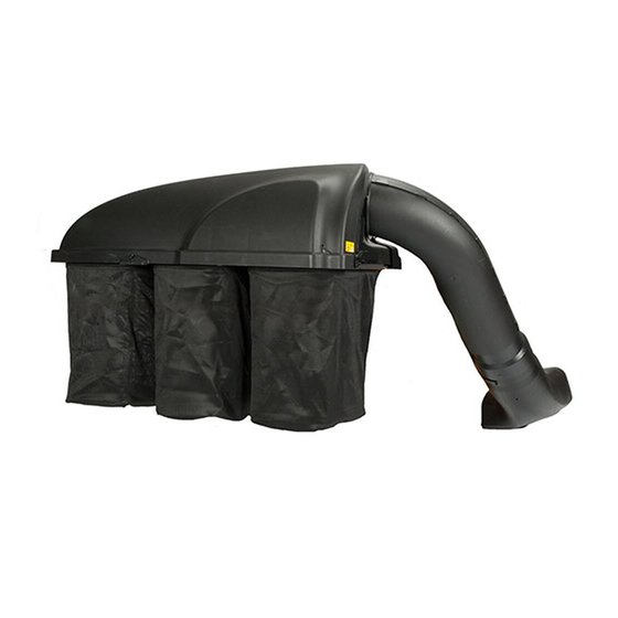
Triple Rear Bagger — 19A70040100
WARNING
READ AND FOLLOW ALL SAFETY RULES AND INSTRUCTIONS IN THIS MANUAL
BEFORE ATTEMPTING TO OPERATE THIS MACHINE.
FAILURE TO COMPLY WITH THESE INSTRUCTIONS MAY RESULT IN PERSONAL INJURY.
CUB CADET LLC, P.O. BOX 361131 CLEVELAND, OHIO 44136-0019
Printed In USA
Form No. 769-09616B
(June 29, 2015)
Advertisement

Related Manuals for Cub Cadet 19A70040100


Summary of Contents for Cub Cadet 19A70040100
- Page 1 READ AND FOLLOW ALL SAFETY RULES AND INSTRUCTIONS IN THIS MANUAL BEFORE ATTEMPTING TO OPERATE THIS MACHINE. FAILURE TO COMPLY WITH THESE INSTRUCTIONS MAY RESULT IN PERSONAL INJURY. CUB CADET LLC, P.O. BOX 361131 CLEVELAND, OHIO 44136-0019 Printed In USA Form No. 769-09616B...
-
Page 2: Table Of Contents
See How-to Maintenance and Parts Installation Videos at www.cubcadet.com/tutorials ◊ Call a Customer Support Representative at (800) 965-4CUB ◊ Locate your nearest Cub Cadet Dealer at (877) 282-8684 ◊ Write to Cub Cadet LLC • P.O. Box 361131 • Cleveland, OH • 44136-0019... -
Page 3: Safe Operation Practices
Important Safe Operation Practices WARNING! This symbol points out important safety instructions which, if not followed, could endanger the personal safety and/or property of yourself and others. Read and follow all instructions in this manual before attempting to operate this machine. Failure to comply with these instructions may result in personal injury. - Page 4 General Service Use slow speed. Choose a low enough speed setting so that you will not have to stop or shift while on the slope. Before cleaning, repairing, or inspecting, make certain the Tires may lose traction on slopes even though the brakes blade(s) and all moving parts have stopped.
- Page 5 2 — i ection mportant peration racticeS...
-
Page 6: Carton Contents & Hardware Packs
Contents of Carton Before beginning installation, remove all parts from the carton to make sure everything is present. Carton contents are listed and shown below. Three hardware packs are included in this kit and are detailed on the following page. •... - Page 7 CONTENTS OF HARDWARE PACK This grass collector kit is shipped with three loose hardware packs enclosed. Please check your hardware packs against the illustrations below. The quantities for each item is listed in parenthesis. 3 — c ection ontentS of arton...
-
Page 8: Assembly & Installation
Assembly & Installation IMPORTANT: Note: The 712-3010 hex nuts should be tightened (against If installing this bagging kit on a ZF-L (lap bar) unit, bumper adaptor kit 19A70046100 is required and must be bumper if bolts are inside-out, or against bracket if bolts installed prior to attempting to install this bagger. - Page 9 Note: If you decided to leave the hitch support only Snap the plastic upper chute support in place by first finger tight during the assembly process, tighten all of the clipping the side portion onto the bagger support rail (1) hardware securely at this time.
- Page 10 Clip in the other side by flexing the screen and pushing it down into the provided cutout hole. See Figure 4-8. Make sure screen sits under the cover’s lip Figure 4-8 Figure 4-10 Install the bagger cover onto the bag support assembly, as seen in Figure 4-9.
- Page 11 Installing the Deck Baffle Open the bagger cover by pushing in on the rear, right-side tab with your right hand, as seen in 1 of Figure 4-12, and Note: Installing the deck baffle may be easiest with the deck lifting the cover with your left hand in the center rear of the removed as instructed in the tractor’s operator’s manual, however bagger cover, 2.
- Page 12 Assembling the Discharge Chute Components Insert the inner boot bracket into the chute elbow as shown in Figure 4-15. Install the discharge chute top mounting bracket onto the topside of the discharge chute using five (5) 710-0751 hex bolts, as shown in Figure 4-15, and securing with three (3) 736-0270 bevel washers and five (5) 712-3027 flange lock nuts, all included in hardware pack 689-00337.
- Page 13 Attach the retainer strap on the discharge chute to the retainer clip on the deck. See Figure 4-20. Flange Figure 4-18 Installing the Discharge Chute On The Tractor Figure 4-20 Reinstall the cutting deck, if previously removed, to the Install the chute adapter onto the chute elbow by lining up tractor reversing the instructions for Deck Removal in the tabs and sliding the adapter over the chute elbow, as operator’s manual of the tractor.
- Page 14 Note: Make sure to align the upper chute with the ridges Install the upper chute tube over the chute tube extension, as shown in Figure 4-22. on the bagger support bracket, as shown in the inset of Figure 4-24. Figure 4-24 Figure 4-22 Secure the upper chute tube to the lower discharge chute by stretching the rubber strap on the upper chute tube...
-
Page 15: Operation
Operation Bagger Usage Remove the grass bags, as shown in Figure 5-2, by lifting each bag up (1) and moving the bags away from the bag NOTE: When all of the grass bags are full, place the tractor on a support assembly (2). -
Page 16: Parts List
19A70040100 Parts List... - Page 17 Ref. Part Number Description 912-3027 Hex Flange Nut, 1/4-20 736-0270 Bevel Washer, .265 x .750 x .060 912-0442 Cap Lock Nut, 1/4-20 710-0751 Hex Head Screw, 1/4-20 x .620 710-3013 Hex Head Screw, 1/4-20 x .50 736-3092 Flat Washer, .265 x 1.0 x .030 712-04064 Flange Lock Nut, 1/4-20 603-05167...
- Page 18 Notes...
- Page 19 7 — n ection oteS...
-
Page 20: Warranty
The limited warranty set forth below is given by Cub Cadet LLC with deck adjustments, and normal deterioration of the exterior respect to new merchandise purchased or leased and used in the finish due to use or exposure.