Table of Contents
Advertisement
Quick Links
1.800.561.8187
Introduction
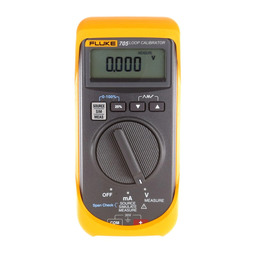
The Fluke 705 Loop Calibrator is a source and measurement tool
for 0 to 20 mA or 4 to 20 mA current loop testing and a
measurement tool for dc voltage from 0 to 28 V. The calibrator
does not source and measure simultaneously.
Your calibrator is supplied with a set of TL75 test leads, AC72
alligator clips, 9 V installed alkaline battery, and this instruction
sheet.
Summary of Calibrator Capabilities
Function
dc V input
dc mA input
dc mA output
Loop power
output
Safety Information
Use the calibrator only as specified in this sheet, otherwise the
protection provided by the calibrator may be impaired.
A Warning identifies conditions and actions that pose hazard(s)
to the user; a Caution identifies conditions and actions that may
damage the calibrator or the equipment under test.
August 1998 Rev.2, 6/03
© 1998-2003 Fluke Corporation, All rights reserved.
All product names are trademarks of their respective companies
www.
English Instruction Sheet
Loop Calibrator
Instruction Sheet
Range
Resolution
+28 V
0.001 V
0 to 24 mA
0.001 mA
24 V dc output
N/A
.com
Page 1
®
705
information@itm.com
Advertisement
Table of Contents

Related Manuals for Fluke 705


Summary of Contents for Fluke 705
- Page 1 Instruction Sheet Introduction The Fluke 705 Loop Calibrator is a source and measurement tool for 0 to 20 mA or 4 to 20 mA current loop testing and a measurement tool for dc voltage from 0 to 28 V. The calibrator does not source and measure simultaneously.
-
Page 2: Explanation Of International Symbols
English Instruction Sheet Page 2 Warning To avoid possible electric shock or personal injury: • Never apply more than 30 V between any two terminals, or between any terminal and earth ground. • Inspect the test leads for damaged insulation or exposed metal. -
Page 3: Pushbutton Functions
English Instruction Sheet Page 3 Pushbutton Functions Button Function Press to select source, simulate, or measure modes. Press while turning on the calibrator to select loop power. The Loop symbol appears in the display. Press simultaneously to start the SpanCheck function. - Page 4 English Instruction Sheet Page 4 Sourcing mA Use source mode whenever you need to supply current into a passive circuit. Insert the test leads into the terminals as shown below. Note A path must exist for current to flow between the output + and −mA terminals, otherwise the display will indicate an overload (OL) when you set an output value.
-
Page 5: How To Contact Fluke
How to Contact Fluke LIMITED WARRANTY & LIMITATION OF LIABILITY This Fluke product will be free from defects in material and workmanship for three years from the date of purchase. This warranty does not cover fuses, disposable batteries or damage from accident, neglect, misuse or abnormal conditions of operation or handling. -
Page 6: Simulating A Transmitter
English Instruction Sheet Page 6 Simulating a Transmitter When simulating the operation of a transmitter, the calibrator regulates the loop current to a known value that the user selects. A 12 to 28 V loop supply must be available. Insert the test leads as shown below. -
Page 7: Auto Ramping The Ma Output
English Instruction Sheet Page 7 Auto Ramping the mA Output Auto ramping allows you to continuously apply a varying current stimulus from the calibrator to a passive (sourcing) or active (simulate) loop while your hands remain free to test the transmitter’s response. - Page 8 English Instruction Sheet Page 8 Changing the Current Span The calibrator’s current output span has two settings: • 4 mA = 0 %, 20 mA = 100 % (default) • 0 mA = 0 %, 20 mA = 100 % (optional) To change and save the current output span in a nonvolatile memory (retained when the power is turned off), press U while turning on the calibrator to mA.
-
Page 9: Measuring Dc Ma With Loop Power
English Instruction Sheet Page 9 Measuring dc mA with Loop Power Loop power provides +24 V to power a transmitter and to read loop current simultaneously. To exit, turn the calibrator off or to V. LOOP CALIBRATOR Measure Press and hold while turning on the calibrator to mA. -
Page 10: Measuring Dc Volts
• Remove any input signals prior to removing test leads and opening case. • When servicing the calibrator, use only specified replacement parts. For maintenance procedures not described in this sheet, contact a Fluke Service Center. 1.800.561.8187 information@itm.com www. .com... - Page 11 In Case of Difficulty Check the battery and test leads. Replace as needed. If the calibrator needs repair, contact a Fluke Service Center. If the calibrator is under warranty, see the warranty statement for terms. If the warranty has lapsed, the calibrator will be repaired and returned for a fixed fee.
- Page 12 English Instruction Sheet Page 12 Replacing the Battery Warning To avoid false readings, which could lead to possible electric shock or personal injury, replace the battery as soon as the battery indicator ( ) appears in the display. rt07f.eps 1.800.561.8187 information@itm.com www.
-
Page 13: Replacement Parts And Accessories
English Instruction Sheet Page 13 Replacement Parts and Accessories Replacement Parts PN or Item Description Model No. Qty. 9 V battery, ANSI/NEDA 614487 1604A or IEC 6LR61 Holster, Yellow MP85 Case top 665098 MP86 Case bottom 665109 Case screw 832246 MP89 Non-skid foot 885884... - Page 14 English Instruction Sheet Page 14 MP85 MP86 MP89 MP92 CD-ROM AC72 Alligator Clips TL75 Test Lead Set rt10f.eps 1.800.561.8187 information@itm.com www. .com...
-
Page 15: Specifications
English Instruction Sheet Page 15 Specifications Specifications are based on a one year calibration cycle and apply from +18 °C to +28 °C unless stated otherwise. “Counts” means number of increments or decrements of the least significant digit. DC Volts Input Range: + 28 V (+ 30 V max) Input Impedance: 1 MΩ... - Page 16 English Instruction Sheet Page 16 General Specifications Maximum voltage applied between any terminal and earth ground or between any two terminals: 30 V Storage temperature: -40 °C to 60 °C Operating temperature: -10 °C to 55 °C Operating altitude: 3000 meters maximum Temperature coefficient: ±0.005 % of range per °C for the temperature ranges -10 to 18 °C and 28 to 55 °C Relative humidity: 95 % up to 30 °C, 75 % up to 40 °C, 45 % up...