Table of Contents
Advertisement
Quick Links
Operation & Maintenance
Manual
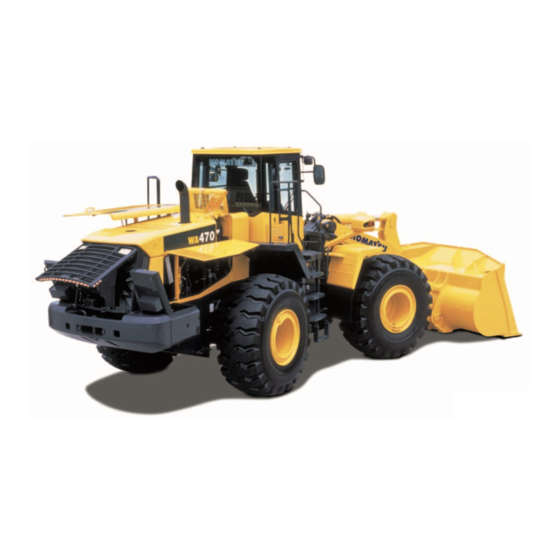
WHEEL LOADER
SERIAL NUMBERS WA470H50051 AND UP
Incorrect operation and maintenance of this machine
may be hazardous and cause injuries. The operator and
maintenance personnel must read this manual before
commencing operation or maintenance. Keep this
manual within reach at all times and ensure that
operating personnel read it at regular intervals.
Komatsu has had the operating and maintenance instructions
translated into all the languages of the European Union.
Should you require a copy in another language please inquire
.
at your local dealer's
DANGER
NOTE
VEAM180100
-5H
Advertisement
Table of Contents

Related Manuals for Komatsu WA470-5H

Summary of Contents for Komatsu WA470-5H
- Page 1 NOTE Komatsu has had the operating and maintenance instructions translated into all the languages of the European Union. Should you require a copy in another language please inquire...
- Page 3 FOREWORD...
- Page 4 If you sell the machine, be sure to give this manual to the new owners together with the machine. Komatsu delivers machines that comply with all applicable regulations and standards of the country to which it has been shipped. If this machine has been purchased in another country or purchased from someone in another country, it may lack certain safety devices and specifications that are necessary for use in your country.
- Page 5 ! The transmitter unit must be spatially separated from the vehicle’s electronic system ! Make sure when installing the antenna that this is installed correctly with good earth connection between antenna and vehicle mass Also observe Komatsu and manufacturer’s installation instructions for wiring, installation and maximum permitted power consumption...
-
Page 6: Safety Information
FOREWORD SAFETY INFORMATION SAFETY INFORMATION To enable you to use this machine safely, safety precautions and labels are given in this manual and affixed to the machine to give explanations of situations involving potential hazards and of the methods of avoiding such situa- tions. - Page 7 Continuing improvements in the design of this machine can lead to changes in detail which may not be reflected in this manual. Consult Komatsu or your Komatsu distributor for the latest available information of your machine or for questions regarding information in this manual.
-
Page 8: Introduction
FOREWORD INTRODUCTION INTRODUCTION This loader is a machine with independent transmission, moving on chains or wheels. Driving in forward direction, the loader can load or dig material using its attachments intended for loading operations (i.e. bucket). The standard operation cycle of a loader includes filling up and loading of the bucket, transporting the material and emptying the bucket. -
Page 9: Necessary Information
FOREWORD NECESSARY INFORMATION NECESSARY INFORMATION When requesting service or ordering replacement parts, please inform your Komatsu distributor of the following items. MACHINE SERIAL NO. PLATE AND POSITION On the center right of the front frame. ENGINE SERIAL NO. PLATE AND POSITION This is at the top of the side face of the engine of the cylinder block on the left side of the machine and on the muf- fler bracket on the right side of the machine. -
Page 10: Rops/Fops-Cab Serial No. Plate
FOREWORD NECESSARY INFORMATION ROPS/FOPS-CAB SERIAL NO. PLATE This plate is located on the right inside cab on the rear beam. AXLE SERIAL NO. PLATE This plate is located on the right of front axle and on the left of rear axle. TRANSMISSION SERIAL NO. -
Page 11: Position Of Service Meter
FOREWORD NECESSARY INFORMATION POSITION OF SERVICE METER It is at the center bottom of the machine monitor. For details of the service meter display, see SERVICE METER in EXPLANATION OF COMPONENTS “SERVICE METER ( 3- 8 )“. TABLE TO ENTER SERIAL NO. AND DISTRIBUTOR Machine serial No. -
Page 12: Table Of Contents
TABLE TO ENTER SERIAL NO. AND DISTRIBUTOR ................... 1-9 CONTENTS ................................ 1-10 DIMENSIONS, WEIGHTS AND OPERATING DATA ..................1-17 WA470-5H: DIMENSIONS, WEIGHTS AND OPERATING DATA..............1-17 CE-CONFORMING EQUIPMENT........................1-18 CE-CONFORMING EQUIPMENT - PART 1....................1-18 MANUFACTURER-SUPPLIED CE-CONFORMING EQUIPMENT, ACCORDING TO DOCUMENT 421-93- H1900 ............................... - Page 13 FOREWORD CONTENTS OPERATION GENERAL VIEW ..............................3-2 GENERAL VIEW OF MACHINE ........................3-2 GENERAL VIEW OF CONTROLS AND GAUGES..................3-3 EXPLANATION OF COMPONENTS........................3-6 MACHINE MONITOR ............................3-6 TYPES OF WARNING..........................3-7 CENTRAL WARNING LAMP ........................3-7 CHARACTER DISPLAY PORTION ......................3-8 EMERGENCY STOP ITEM ........................
-
Page 14: Contents
FOREWORD CONTENTS OPERATION OF WORK EQUIPMENT ......................3-98 WORK POSSIBLE USING WHEEL LOADER ..................... 3-100 DIGGING OPERATIONS........................3-100 LEVELING OPERATIONS........................3-104 PUSHING OPERATION ......................... 3-104 LOAD AND CARRY OPERATIONS ....................... 3-104 LOADING OPERATIONS ........................3-105 PRECAUTIONS FOR OPERATION ......................3-107 PERMISSIBLE WATER DEPTH ...................... - Page 15 OUTLINE OF OIL, FUEL, COOLANT ......................4-4 OIL ................................4-4 FUEL................................4-4 COOLANT..............................4-4 GREASE ..............................4-5 CARRYING OUT KOWA (Komatsu Oil Wear Analysis) ................4-5 STORING OIL AND FUEL .......................... 4-6 FILTERS ..............................4-6 OUTLINE OF ELECTRIC SYSTEM......................... 4-6 WEAR PARTS LIST ............................. 4-7 THE PARTS IN PARENTHESES ARE TO BE REPLACED AT THE SAME TIME .........
- Page 16 FOREWORD CONTENTS CLEAN ELEMENT IN AIR CONDITIONER FRESH AIR FILTER............. 4-40 EVERY 250 HOURS SERVICE ........................4-41 CHECK ENGINE ELECTROLYTE LEVEL ....................4-41 CHECK PARKING BRAKE ........................4-42 CHECK ALTERNATOR BELT TENSION, ADJUST ................. 4-43 CHECK AIR CONDITIONER COMPRESSOR BELT TENSION, ADJUST ..........4-44 CHECK FOR LOOSE WHEEL HAB NUTS, TIGHTEN................
- Page 17 FOREWORD CONTENTS ATTACHMENTS, OPTIONS HANDLING LOAD METER ..........................6-2 GENERAL LOCATIONS ..........................6-2 MACHINE MONITOR WITH LOAD METER....................6-2 SWITCHES ..............................6-3 LOAD METER FUNCTIONS..........................6-4 HANDLING LOAD METER DISPLAY......................6-7 SETTING ADDITION MODE ........................6-7 SETTING REMAIN MODE.......................... 6-9 TOTAL LOAD DATA DISPLAY.........................
- Page 18 FOREWORD CONTENTS INDEX ................................... 7-1 NOTES NOTES.................................. 8-2 1-16...
-
Page 19: Dimensions, Weights And Operating Data
FOREWORD DIMENSIONS, WEIGHTS AND OPERATING DATA DIMENSIONS, WEIGHTS AND OPERATING DATA WA470-5H: DIMENSIONS, WEIGHTS AND OPERATING DATA WA470-5Abm Measurements, operating data Bucket capacity to ISO 7546 m³ Material density t/m³ Bucket weight without teeth 1.690 Static tipping load, straight 18.400 Static tipping load, 40°... -
Page 20: Ce-Conforming Equipment
4,75 2.450 421-70-H2E84 4,75 2.590 421-70-H2E91 4,35 2.340 421-70-H2F92 4,75 2.542 421-70-H2G71 2.349 421-70-H2G82 2.712 421-70-H2K52 2.107 421-70-H2K62 2.243 Bucket WA470-5H 421-70--H2K73 2.360 421-70-H2K84 2.590 421-70-H2P12 2.340 421-70-H2P22 2.480 421-70-H2P31 4,25 2.549 421-70-H2S02 2.350 421-70-H2S12 2.485 421-70-H2S21 4,25 2.559 421-71-H2001 1.750... -
Page 21: Manufacturer-Supplied Ce-Conforming Equipment, According To Document 421-93-H1900
FOREWORD CE-CONFORMING EQUIPMENT MANUFACTURER-SUPPLIED CE-CONFORMING EQUIPMENT, ACCORDING TO DOCUMENT 421-93-H1900 The responsibility for observing valid regulations in the case of wheel loaders with "interchangeable equipment" (e.g. bucket or fork-lift) which was not supplied from works lies with the customer which was subsequently fitted to the machine. The directives for CE conformity and road-traffic registration are deemed to have been fulfilled when the manufacturer of the equipment confirms fulfilment of the form 421-93-H1900... - Page 22 FOREWORD CE-CONFORMING EQUIPMENT d1=d2 GK100395 1-20...
- Page 23 FOREWORD CE-CONFORMING EQUIPMENT MANUFACTURER- SUPPLIED CE-CONFORMING EQUIP- MENT, ACCORDING TO DOCUMENT 421-93-H1900 WA470-5H 421-93-H1900 A1 Distance: bucket pivoting point - front axle, horizontal 2245 A2 Distance: bucket pivoting point - front axle, vertical 1345 Sh Distance: road level - front axle...
- Page 24 FOREWORD CE-CONFORMING EQUIPMENT 1-22...
-
Page 25: Safety
SAFETY... - Page 26 SAFETY...
-
Page 27: Safety Labels
If the safety labels are damaged or lost, or cannot be read, replace them with new parts. For details of the part numbers, see this manual or check on the actual part, and order the new part from your Komatsu distributor. -
Page 28: Safety Labels
Keep a safe distance to the bucket cylinder Caution, hot water/oil P/N: 421-93-H1380 P/N: 421-93-H1280 Keep a safe distance to the machine´s articulated Use Komatsu oil only joint P/N: 421-93-H1320 P/N: 421-93-H1390 Secure articulated joint during transport or when Keep a safe distance to the attachments... -
Page 29: General Precautions
SAFETY GENERAL PRECAUTIONS GENERAL PRECAUTIONS SAFETY RULES ! Only trained and authorized personnel can operate and maintain the machine. ! Follow all safety rules, precautions and instructions when operating or performing maintenance on the machine. ! If you are under the influence of alcohol or medication, your ability to safely operate or repair your machine may be severly impaired putting yourself and everyone else on your jobsite in danger. - Page 30 SAFETY GENERAL PRECAUTIONS KEEP MACHINE CLEAN ! If water gets into the electrical system, there is a hazard that it will cause malfunctions or misoperation. Do not use water or steam to wash the electrical system (sensors, connectors). ! If inspection and maintenance is carried out when the machine is still dirty with mud or oil, there is a hazard that you will slip and fall, or that dirt or mud will get into your eyes.
- Page 31 SAFETY GENERAL PRECAUTIONS HANDRAILS AND STEPS To prevent personal injury caused by slipping or falling off the machine, always do as follows. ! Use the handrails and steps marked by arrows in the dia- gram on the right when getting on or off the machine. ! To ensure safety, always face the machine and maintain three-point contact (both feet and one hand, or both hands and one foot) with the handrails and steps to ensure that...
- Page 32 SAFETY GENERAL PRECAUTIONS DO NOT GET CAUGHT IN ARTICULATED PORTION ! If the clearance at the articulating portion changes, it will lead to serious personal injury. Do not allow anyone to come inside the articulation range. ! Never enter or put your hand, arm, or any part of your body in the movable portion between the work equipment and machine or between the cylinder and the work equipment.
- Page 33 SAFETY GENERAL PRECAUTIONS FIRE PREVENTION ! Fire caused by fuel or oil Fuel, oil, antifreeze, and window washer liquid are particu- larly flammable and can be hazardous. To prevent fire, always observe the following: ! Do not smoke or use any flame near fuel or oil. ! Stop the engine before refueling.
- Page 34 Any modification mode without authorization from Komatsu can create hazards. Before making a modification, consult your Komatsu distributor. ! Komatsu will not be responsible for any injuries, accidents, or product failures resulting from modifications made without authorization from Komatsu. SAFETY AT WORKSITE Before starting operations, thoroughly check the area for any unusual conditions that could be dangerous.
- Page 35 SAFETY GENERAL PRECAUTIONS WORKING ON LOOSE GROUND ! Avoid traveling or operating your machine too close to the edge of cliffs, overhangs, and deep ditches. The ground may be weak in such areas. If the ground should collapse under the weight or vibration of the machine, there is a hazard that the machine may fall or tip over.
- Page 36 ! Do not allow other persons to approach during the opera- tion. ! Always observe the rules and regulations for the work site and environmental standards. This machine does not use asbestos, but there is a danger that imitation parts may contain asbestos, so always use genuine Komatsu parts. 2-12...
-
Page 37: Precautions For Operation
SAFETY PRECAUTIONS FOR OPERATION PRECAUTIONS FOR OPERATION BEFORE STARTING ENGINE If there is a warning tag hanging from the work equipment con- trol lever, do not start the engine or touch the levers (1). CHECKS BEFORE STARTING ENGINE Carry out the following checks before starting the engine at the beginning of the day‘s work. ! Remove all dirt from the surface of the window glass to ensure a good view. -
Page 38: Operation
SAFETY PRECAUTIONS FOR OPERATION Before charging or starting the engine with a different power source, melt the battery electrolyte and check for frost and leakage of battery electrolyte before starting. OPERATION CHECKS BEFORE STARTING ENGINE When carrying out the checks, move the machine to a wide area where there are no obstructions, and operate slowly. - Page 39 This may cause the tires to burst. If a tire bursts, it produces an extremely large destructive force, and this may cause serious injury or acci- dent. If you are going to travel continuously, please consult your Komatsu distributor. 2-15...
- Page 40 SAFETY PRECAUTIONS FOR OPERATION TRAVELING ON SLOPES To prevent the machine from tipping over or slipping to the side, always do as follows. ! Keep the work equipment approx. 20 to 30 cm (8 to 12 in) above the ground. In case of emergency, lower the work equipment to the ground immediately to help stop the machine.
- Page 41 SAFETY PRECAUTIONS FOR OPERATION ! It is dangerous to use the bucket or lift arm for crane opera- tions, so do not carry out such operations. ! Do not pass the bucket over the head of other workers or over the operator‘s seat of dump trucks or other hauling equipment.
- Page 42 SAFETY PRECAUTIONS FOR OPERATION PRECAUTIONS WHEN OPERATING ! When using the machine, to prevent the machine from overturning due to overloading and to avoid damage to the work equipment, do not exceed the maximum permitted load or performance of the machine. ! If the engine cannot be started again after it has stopped, immediately operate the work equipment control levers to lower the work equipment to the ground.
- Page 43 SAFETY PRECAUTIONS FOR OPERATION OPERATE CAREFULLY ON SNOW ! Snow-covered or frozen surfaces are slippery, so be extremely careful when traveling or operating the machine, and do not operate the levers suddenly. Even a slight slope may cause the machine to slip, so be par- ticularly careful when working on slopes.
- Page 44 SAFETY PRECAUTIONS FOR OPERATION ! If it is necessary to park the machine on a slope, set blocks under the wheels to prevent the machine from moving. 2-20...
-
Page 45: Transportation
PRECAUTIONS FOR OPERATION TRANSPORTATION The machine can be divided into parts for transportation, so when transportating the machine, please contact your Komatsu distributor to have the work carried out. LOADING AND UNLOADING When loading or unloading the machine, mistaken operation may bring the hazard of the machine tipping over or falling, so particular care is necessary. -
Page 46: Battery
SAFETY PRECAUTIONS FOR OPERATION BATTERY BATTERY HAZARD PREVENTION Battery electrolyte contains sulphuric acid, and batteries generate flammable hydrogen gas, which may explode. Mistaken handling can lead to serious injury or fire. For this reason, always observe the following precautions. ! Do not use or charge the battery if the battery electrolyte level is below the LOWER LEVEL line. This may cause an explosion. - Page 47 SAFETY PRECAUTIONS FOR OPERATION STARTING WITH BOOSTER CABLES If any mistake is made in the method of connecting the booster cables, it may cause the battery to explode, so always do as follows. ! When starting with a booster cable, carry out the starting operation with two workers (one worker sitting in the opera- tor‘s seat and the other working with the battery).
-
Page 48: Towing
SAFETY PRECAUTIONS FOR OPERATION TOWING WHEN TOWING Serious injury or death could result if a disabled machine is towed incorrectly or if there is a mistake in the selec- tion or inspection of the wire rope. For towing, see “TOWING THE MACHINE (3-127)“. ! Always wear leather gloves when handling wire rope. -
Page 49: Precautions For Maintenance
SAFETY PRECAUTIONS FOR MAINTENANCE PRECAUTIONS FOR MAINTENANCE WARNING TAG ! Always attach the “DO NOT OPERATE“ warning tag to work equipment control lever (1) in the operator‘s cab to alert oth- ers that you are performing service of maintenance on the machine. - Page 50 SAFETY PRECAUTIONS FOR MAINTENANCE MAINTENANCE WITH ENGINE RUNNING ! Stop the machine on firm, level ground. ! Select a place where there is no hazard of falling rocks or landslides, or of flooding if the land is low. ! Lower the work equipment completely to the ground and stop the engine.
- Page 51 SAFETY PRECAUTIONS FOR MAINTENANCE TWO WORKERS FOR MAINTENANCE WHEN ENGINE IS RUNNING To prevent injury, do not carry out maintenance with the engine running. If maintenance must be carried out with the engine running, carry out the operation with at least two workers and do as follows. ! One worker must always sit in the operator‘s seat and be ready to stop the engine at any time.
- Page 52 ! Do not make holes in it, weld it, or use a cutting torch. ! Do not hit or roll the accumulator, or subject it to any impact. ! When disposing of the accumulator, the gas must be released. Please contact your Komatsu distributor to have this work performed. PERSONNEL Only authorized personnel can service and repair the machine.
- Page 53 SAFETY PRECAUTIONS FOR MAINTENANCE WORKING UNDER THE RAISED BOOM WARNING Danger of injury! The raised boom may suddenly fall! For safety reasons, a raised boom must be secured against dropping before you pass or stand under it. ! The boom must be secured against moving if any work is to be carried out under it when it is in a raised position.
- Page 54 If any loose bolts are found, stop work and tighten to the specified torque. ! If any damaged hoses are found, stop operations immediately and contact your Komatsu distributor. ! Replace all hoses every six years at the latest. The shelf life of the hose should not exceed 2 years.
- Page 55 SAFETY PRECAUTIONS FOR MAINTENANCE WASTE MATERIALS To prevent pollution, pay careful attention to the method of disposing of waste materials. ! Always put oil drained from your machine in containers. Never drain oil directly onto the ground or dump into the sewage system, rivers, the sea, or lakes.
-
Page 56: Precautions With Tires
Komatsu distributor to carry out these operations. ! Always use the tires specified by Komatsu and maintain the specified inflation pressure. Suitable tire inflation pressure: see “HANDLING THE TIRES (3-115)“... - Page 57 OPERATION...
-
Page 58: Operation
OPERATION GENERAL VIEW GENERAL VIEW GENERAL VIEW OF MACHINE 1) Bucket (8) Turn signal lamp (2) Tilt lever (9) Head lamp (3) Front wheel (10) Lift cylinder (4) Bucket cylinder (11) Lift arm (5) Front working lamp (12) Rear working lamp (6) ROPS cab (13) Rear combination lamp (7) Rear wheel... -
Page 59: General View Of Controls And Gauges
OPERATION GENERAL VIEW GENERAL VIEW OF CONTROLS AND GAUGES (1) Directinal lever stopper (14) Parking brake switch (2) Rear wiper switch (15) Cigarette lighter (3) Front wiper switch (16) Load meter cancel switch (option) (4) Speed control lever (17) Kickdown switch (5) Front switch panel (18) Lift arm control lever (6) Directinal lever... - Page 60 OPERATION GENERAL VIEW MACHINE MONITOR (1) Central warning lamp (20) Joystick pilot lamp (option) (2 )Brake oil pressure caution lamp (21) Directional selector pilot lamp (option) (3) Engine oil pressure caution lamp (22) Shift indicator (4) Engine oil level caution lamp (23) Auto-shift pilot lamp (5) Radiator water level caution lamp (24) Lockup pilot lamp (option)
- Page 61 OPERATION GENERAL VIEW SWITCH PANEL RIGHT SWITCH PANEL FRONT SWITCH PANEL (1) Transmission shift mode selector switch (14) Monitor panel mode selector switch 1 (2) Transmission cut-off set switch (15) Monitor panel mode selector switch 2 (3) Cooling fan reverse rotation switch (16) Front working lamp switch (4) Emergency steering switch (17) Rear working lamp switch...
-
Page 62: Explanation Of Components
! The indicator gauges and meters are actuated after the above system check is completed. ! The character display shows “KOMATSU SYSTEM CHECK“ for 3 seconds. ! If the lamps do not light up, there is probably a failure or disconnection, so contact your Komatsu dis- tributor for inspection. -
Page 63: Types Of Warning
OPERATION EXPLANATION OF COMPONENTS TYPES OF WARNING If an abnormality occurs on the machine, or if any switch or lever is operated mistakenly, the monitor display and buzzer give a warning to inform the operator. There are the following types of warning depending on the level of danger. -
Page 64: Character Display Portion
OPERATION EXPLANATION OF COMPONENTS CHARACTER DISPLAY PORTION (1) Service meter (3) Action code display (2) Clock (only machines equipped with optional load (4) Failre code display meter) (5) Filter, oil replacement time display Normally, the service meter is displayed on the character display. If the machine has failed, or if there has been excessive load on the machine, or if it is necessary to carry out inspection and maintenance, an action code is displayed to recommend suitable action. - Page 65 “FAILURE CODE DISPLAY ( 3-11 )“. Inform your Komatsu distributor of the failure code and ask for repairs. If there is a failure on the machine, or it is necessary to change the method of operation, or if inspection or mainte- nance must be carried out, action code E00, E01, E02, or E03 is displayed on the character display in display por- tion (3).
- Page 66 If the overheat related display is given, stop the machine and run the engine under no load at a mid-range speed. If an action code is still displayed after doing this, check the failure code and contact your Komatsu distributor for repairs. REMARK The top line of the character display displays “E02“...
- Page 67 If an action code is displayed on the character display, check the failure code according to the failure code display method given below. When contacting your Komatsu distributor to request repairs, please inform your distributor of the failure code. Method of displaying failure code 1.
- Page 68 OPERATION EXPLANATION OF COMPONENTS FILTER, OIL REPLACEMENT TIME DISPLAY After completion of the system check when the starting switch is turned ON, if any filter or oil item is approaching the replace- ment time, this display (5) shows the item for approx. 30 sec- onds.
- Page 69 OPERATION EXPLANATION OF COMPONENTS REMARK See the section below for details of the procedure for replacing the filter and oil. ! Engine oil “CHANGE OIL IN ENGINE OIL PAN, REPLACE ENGINE OIL FILTER CARTRIDGE ( 4-46 )“ ! Engine oil filter “CHANGE OIL IN ENGINE OIL PAN, REPLACE ENGINE OIL FILTER CARTRIDGE ( 4-46 )“...
-
Page 70: Emergency Stop Item
OPERATION EXPLANATION OF COMPONENTS EMERGENCY STOP ITEM CAUTION If these monitors light up and the buzzer sounds, stop operations immediately and carry out inspection and maintenance of the applicable location. If any abnormality is found in the emergency stop items, the alarm buzzer will sound intermittently, and the monitor for the location of the abnormality and the central warning lamp will light up. - Page 71 OPERATION EXPLANATION OF COMPONENTS BRAKE OIL PRESSURE CAUTION LAMP This monitor (1) lights up when the brake oil pressure goes below the specified value. During checks before starting (when the starting switch is turned to the ON position but the engine is not started), the brake circuit is not actuated while the engine is stopped, so the brake oil pressure caution lamp and central warning lamp do not light up and the alarm buzzer does not sound.
- Page 72 OPERATION EXPLANATION OF COMPONENTS BATTERY CHARGE CIRCUIT CAUTION LAMP This monitor (3) lights up when the engine is running to warn the operator that an abnormality has occurrred in the charging circuit. During checks before starting (when the starting switch is turned to the ON position but the engine is not started), this monitor does not light up.
-
Page 73: Caution Items
OPERATION EXPLANATION OF COMPONENTS CAUTION ITEMS CAUTION If these monitors light up, stop operations quickly and carry out the following action. (1) Axle oil temperature caution lamp (4) Hydraulic oil temperature caution lamp (2) Torque converter oil temperature caution lamp (5) Fuel level caution lamp (3) Engine cooling water temperature caution lamp AXLE OIL TEMPERATURE CAUTION LAMP... - Page 74 OPERATION EXPLANATION OF COMPONENTS At the same time, “E02 BRAKE OVERHEAT“ is displayed on the character display, so take the following action. 1. Release the accelerator pedal and move the gearshift lever down one range to reduce the travel speed. 2.
- Page 75 OPERATION EXPLANATION OF COMPONENTS HYDRAURIC OIL TEMPERATURE CAUTION LAMP This monitor (4) lights up to warn the operator that the hydrau- lic oil temperature has risen. During checks before starting (when the starting switch is turned to the ON position but the engine is not started), this monitor does not light up.
-
Page 76: Inspection And Maintenance Item
OPERATION EXPLANATION OF COMPONENTS INSPECTION AND MAINTENANCE ITEM CAUTION If these monitors light up, stop operations quickly and carry out the following action. (1) Engine oil level caution lamp (5) Battery electrolyte level caution lamp (option) (2) Radiator water level caution lamp (6) Breakeoil level caution lamp (3) Air cleaner clogging caution lamp (7) Transmission oil filter clogging caution lamp... - Page 77 OPERATION EXPLANATION OF COMPONENTS REMARK During checks before starting, if the engine is started with the engine oil level caution lamp lighted up, the lamp will stay lighted up. During operation (engine running) If the oil level in the engine oil pan becomes too low, the engine oil level caution lamp will light up. At the same time, “E01 ENG OIL LEV LOW“...
- Page 78 OPERATION EXPLANATION OF COMPONENTS MAINTENANCE CAUTION LAMP CAUTION If the caution monitor lamp lights up, repair the problem as soon as possible. When the oil change interval is reached, this monitor (4) flashes or lights up for approx. 30 seconds after completion of the system check when the starting switch is at the ON posi- tion.
- Page 79 OPERATION EXPLANATION OF COMPONENTS BRAKE OIL LEVEL CAUTION LAMP This monitor (6) is not used. On this machine, the hydraulic oil is used for the brake oil. TRANSMISSION OIL FILTER CLOGGING CAUTION LAMP This monitor (7) is not used. 3-23...
-
Page 80: Pilot Display Portion
OPERATION EXPLANATION OF COMPONENTS PILOT DISPLAY PORTION When the starting switch is ON, the pilot display lights up when the display items are functioning. (1) Parking brake pilot lamp (9) Directional selector pilot lamp (option) (2) Cooling fan reverse rotation pilot lamp (10) Shift indicator (3) Emergency steering pilot lamp (11) Aut-shift pilot lamp... - Page 81 OPERATION EXPLANATION OF COMPONENTS COOLING FAN REVERSE ROTATION PILOT LAMP This monitor (2) lights up when the direction of rotation of the cooling fan is reversed. At the same time, “COOLING FAN REVERSE“ is displayed on the character display. REMARK When the engine is running, even if the cooling fan reverse switch is operated, the fan does not rotate in reverse.
- Page 82 OPERATION EXPLANATION OF COMPONENTS SEMI AUTO DIGGING PILOT LAMP (If equipped) This monitor (6) lights up when the mode is set to the semi auto digging mode and the bucket is automatically tilted. AUTO-GREASING PILOT LAMP This monitor (7) lights up when the auto-greasing is actuated. If the grease tank is empty, this lamp flashes (1 Hz) and if there is any abnormality in the auto-greasing system, it flashes rap- idly (2 Hz).
- Page 83 OPERATION EXPLANATION OF COMPONENTS DIRECTIONAL SELECTOR PILOT LAMP This monitor (9) lights up when the directional selector switch actuation switch on the right switch panel is turned ON to make it possible to switch the direction of travel between FORWARD and REVERSE with the directional selector switch at the side of the lift arm control lever.
- Page 84 OPERATION EXPLANATION OF COMPONENTS SHIFT HOLD PILOT LAMP This monitor (13) lights up when the shift hold is actuated. SHIFT LEVER POSITION PILOT LAMP This monitor (14) displays the transmission position of the gearshift lever. TURN SIGNAL PILOT LAMP This monitor (15) flashes at the same time as the turn signal lamp flashes.
-
Page 85: Meter Display Portion
OPERATION EXPLANATION OF COMPONENTS METER DISPLAY PORTION (1) Torque converter oil temperature gauge (4) Fuel gauge (2) Engine water temperature gauge (5) Speedometer (3) Hydraulic temperature gauge (6) Meter display pilot lamp TORQUE CONVERTER OIL TEMPERATURE GAUGE This meter (1) indicates the torque converter oil temperature. It should be in the white range during operation. - Page 86 The display unit is indicated on meter display pilot lamp (6). It is also possible to display the engine speed by switching meter (5). If you wish to switch between the speedometer and tachome- ter, please contact your Komatsu distributor to have it switched. 3-30...
-
Page 87: Other Functions Of Machine Monitor
OPERATION EXPLANATION OF COMPONENTS METER DISPLAY PILOT LAMP This lamp (6) displays the unit for the travel speed or engine tachometer. OTHER FUNCTIONS OF MACHINE MONITOR The machine monitor also has the following functions. Odometer, filter/oil replacement time reset, telephone number input, language selection, monitor brightness adjustment METHOD OF DISPLAYING ODOMETER Use this when checking the total distance that the machine has traveled. - Page 88 OPERATION EXPLANATION OF COMPONENTS RESET METHOD FOR FILTER, OIL REPLACEMENT TIME The filter and oil replacement time is displayed on the character display, so if the filter and oil have been replaced, reset the filter and oil change time. 1. Press the (&) of monitor panel mode selector switch 1, and display the odometer. 2.
- Page 89 OPERATION EXPLANATION OF COMPONENTS INPUT METHOD FOR TELEPHONE NUMBER It is possible to display the telephone number on the right side of “CALL“ displayed on the character display when action code “E03“ is generated. 1. Press the (&) of monitor panel mode selector switch 1, and display the odometer. 2.
- Page 90 OPERATION EXPLANATION OF COMPONENTS METHOD FOR SELECTING LANGUAGE Use this when switching the language displayed on the character display. The following explanation is for when english is set as the language for the character display. 1. Press the (&) of monitor panel mode selector switch 1, and display the odometer. 2.
- Page 91 OPERATION EXPLANATION OF COMPONENTS METHOD OF ADJUSTING MONITOR BRIGHTNESS Do as follows to adjust the brightness of the monitor. 1. Press the (&) of monitor panel mode selector switch 1, and display the odometer. 2. Press the (>) or (<) monitor panel mode selector switch 2 and display "BRIGHTNESS ADJUST".
-
Page 92: Switches
OPERATION EXPLANATION OF COMPONENTS SWITCHES 3-36... - Page 93 OPERATION EXPLANATION OF COMPONENTS (1) Starting switch (17) Rear wiper switch (2) Power mode selector switch (18) Cigarette lighter (3) Transmission shift mode selector switch (19) Room lamp switch (4) Transmission cut-off switch (20) Rear heated wire glass switch (5) Transmission cut-off set switch (21) E.C.S.S.
- Page 94 OPERATION EXPLANATION OF COMPONENTS POWER MODE SELECTOR SWITCH This switch (2) can be used to switch the engine output to match the purpose of the operation. When the POWER mode is selected, the output mode pilot lamp (POWER mode) on the machine monitor lights up. NORMAL position: Normal mode (low engine output), opera- tions where emphasis is on fuel consumption, such as operations on flat ground where high engine output is not...
- Page 95 OPERATION EXPLANATION OF COMPONENTS TRANSMISSION CUT-OFF SWITCH WARNING When moving the machine off on an uphill slope, set the transmission cut-off switch to the OFF position, depress the accelerator pedal while keeping the left brake pedal depressed, then gradually release the brake pedal and allow the machine to move.
- Page 96 OPERATION EXPLANATION OF COMPONENTS LAMP SWITCH This switch (6) is used to light up the front lamps, side clear- ance lamps, tail lamps, and instrument panel. Position (a): OFF Position (b): Side clearance lamps, tail lamps, and instrument panel light up Position (c): Head lamps light up in addition to lamps at (b) position REMARK...
- Page 97 ! If the parking brake has been used as an emergency brake when traveling at high speed, contact your Komatsu distributor to have the parking brake checked for any abnormality. REMARK ! When the parking brake is applied, the machine will not move off even if the directional lever is oper- ated.
- Page 98 OPERATION EXPLANATION OF COMPONENTS FRONT WORKING LAMP SWITCH WARNING Always turn the working lamp off before traveling on pub- lic roads. When turning the front working lamp ON, operate the lamp switch to turn the side clearance lamp ON or the head lamp ON, then operate this switch (10).
- Page 99 OPERATION EXPLANATION OF COMPONENTS MONITOR PANEL MODE SELECTOR SWITCH 2 This switch (13) is used to switch the function of the character display. When the switch is released, it automatically returns to its origi- nal position. The basic operation is as follows. Position (>): Press here to go on to the next screen, or to move the cursor forward, or to increase the number when input- ting numerals...
- Page 100 OPERATION EXPLANATION OF COMPONENTS HOLD SWITCH To fix the speed range when traveling in automatic transmis- sion, press switch (15) at the side of the left arm control lever knob. The transmission will be fixed in the speed range dis- played on shift indicator (A) on the machine monitor and shift hold pilot lamp (B) will light up.
- Page 101 OPERATION EXPLANATION OF COMPONENTS CIGARETTE LIGHTER This is used to light cigarettes. After cigarette lighter (18) is pushed in, it will return to its origi- nal position after a few seconds, so pull it out and light your cig- arette. ROOM LAMP SWITCH The switch (19) is used to turn the room lamp ON and OFF.
- Page 102 OPERATION EXPLANATION OF COMPONENTS E.C.S.S. SWITCH WARNING ! If the machine is traveling or the work equipment is raised, the moment the E.C.S.S. switch is turned ON, the work equipment will move. ! If operations are carried out with the E.C.S.S. switch at the ON position, the moment the E.C.S.S. switch is operated, the work equipment may move.
- Page 103 OPERATION EXPLANATION OF COMPONENTS EMERGENCY STEERING SWITCH This switch (22) is the manual control switch for the emergency steering. Even when the engine has stopped, steering operations are made possible by pressing this switch. Position (a): ON The pilot lamp inside the switch and the emergency steering pilot lamp on the machine monitor light up and it becomes possible to operate the steering.
- Page 104 OPERATION EXPLANATION OF COMPONENTS DIRECTIONAL SELECTOR SWITCH (If equipped) This switch (24) is used to switch the direction of travel of the machine between forward and reverse. F Position: FORWARD N Position: Neutral R Position: REVERSE Before operating this switch, check that the condition is as fol- lows.
- Page 105 OPERATION EXPLANATION OF COMPONENTS REMOTE POSITIONER RAISE MODE SWITCH (If equipped) Use this switch (27) to turn on the remote positioner RAISE mode (operating the lift arm at above the horizontal position). Position (a): RAISE mode ON Position (b): OFF REMOTE POSITIONER LOWER MODE SWITCH (If equipped) Use this switch (28) to turn on the remote positioner LOWER...
- Page 106 OPERATION EXPLANATION OF COMPONENTS AFTERCOOLER TILT SWITCH (If equipped) This switch (30) can be used to tilt the aftercooler electrically. Use this when cleaning the cooler fins. Position (a): Cooler is tilted 17 degrees Position (b): Cooler is returned to original position TORQUE CONVERTER LOCK-UP SWITCH (If equipped) For details of the torque converter lock-up, see “HANDLING TORQUE CONVERTER LOCK-UP ( 6-27 )“...
-
Page 107: Control Levers, Pedals
OPERATION EXPLANATION OF COMPONENTS CONTROL LEVERS, PEDALS (1) Speed control lever (5)Bucket control lever (2) Directinal lever (6) Lift arm control lever (3) Directinal lever stopper (7) Brake pedal (4) Safety lock lever (for wark equipment lever) (8) Accelelator pedal SPEED CONTROL LEVER This lever (1) controls the travel speed of machine. - Page 108 OPERATION EXPLANATION OF COMPONENTS REMARK The length of the lever can be adjusted to 3 stages (posi- tions (A), (B), (C)). To adjust the length, remove the screw at the bottom of the lever knob, slide the knob to the desired position, then tighten the screw again.
- Page 109 OPERATION EXPLANATION OF COMPONENTS To set to the desired speed range when traveling uphill or downhill, or when carrying out grading, do as follows. ! When fixing the speed range Press the HOLD switch on the rift arm control lever. The speed range is fixed at the speed range displayed on the transmission indicator on the main monitor.
- Page 110 OPERATION EXPLANATION OF COMPONENTS SPEED CONTROL LEVER STOPPER This stopper (3) prevents the speed control lever from entering the 3rd positions when working. Position (a): Stopper actuated. Position (b): Stopper released. SAFETY LOCK LEVER (FOR WORK EQUIPMENT LEVER) WARNING ! Before standing up from the operator‘s seat, set the safety lock lever securely to the LOCK position. If the safety lock lever is not at the LOCK position, and work equipment control lever (A) is touched by mistake, it may lead to a serious accident.
- Page 111 OPERATION EXPLANATION OF COMPONENTS BUCKET CONTROL LEVER This lever (5) operates the bucket. Position (a): TILT When the bucket control lever is pulled further from the TILT position, the lever is stopped in this position until the bucket reaches the preset position of the positioner, and the lever is returned to the HOLD position.
- Page 112 OPERATION EXPLANATION OF COMPONENTS BRAKE PEDAL WARNING ! When traveling downhill, use the engine as a brake, and always use the right brake pedal. ! Do not use the brake pedals repeatedly unless neces- sary. ! Do not put your foot on this pedal unless necessary. Thess pedals (7) operate the brakes.
-
Page 113: Steering Tilt Lock Lever
OPERATION EXPLANATION OF COMPONENTS STEERING TILT LOCK LEVER WARNING Stop the machine before adjusting the tilt of the steering wheel. If this operation (adjustment) is carried out while the machine is moving, it may lead to a serious accident or personal injury. This lever is used to set the steering wheel to the FREE posi- tion when adjusting the position of the steering wheel to the front or rear or up or down. -
Page 114: Cap With Lock
OPERATION EXPLANATION OF COMPONENTS CAP WITH LOCK The fuel tank filler port and the hydraulic tank filler port (if equipped) are equipped with locks. Use the starting switch key to open and close the cap. METHOD OF OPENING AND CLOSING CAP WITH LOCK (FOR THE FUEL TANK FILLER PORT) TO OPEN THE CAP 1. -
Page 115: Method Of Opening And Closing Cap With Lock (For The Hydrauric Tank Filler Port)
OPERATION EXPLANATION OF COMPONENTS METHOD OF OPENING AND CLOSING CAP WITH LOCK (FOR THE HYDRAURIC TANK FILLER PORT) (If equipped) TO OPEN THE CAP 1. Insert the starting switch key into the cap as far as it will go (to the shoulder). If the starting switch key is turned before it is inserted all the way,it may break. -
Page 116: Safety Bar
OPERATION EXPLANATION OF COMPONENTS SAFETY BAR WARNING ! When carrying out maintenance or transporting the machine, always fit the safety bar. ! Always remove the safety bar for general travel opera- tions. If it is not removed, the steering wheel cannot be used for steering. -
Page 117: Cab Door Open Lock
OPERATION EXPLANATION OF COMPONENTS CAB DOOR OPEN LOCK When getting in or out of the operator‘s compartment, or when operating with the door open, use this lock to hold the door in position. 1. Push the door against catch (1) to fix it in position. 2. -
Page 118: Fuse
OPERATION EXPLANATION OF COMPONENTS METHOD OF CHANGING Operate the sound pressure selector switch at the rear face of the backup alarm to adjust the volume. FUSE NOTICE Before replacing a fuse, be sure to turn off the starting switch. The fuses protect the electrical equipment and wiring from burning out. -
Page 119: Fuse Capacity And Name Of Circuit
OPERATION EXPLANATION OF COMPONENTS FUSE CAPACITY AND NAME OF CIRCUIT FUSE BOX A No.‚ Fuse capacity Name of circuit Horn, air suspension Transmission control Parking brake Emergency steering Work equipment positioner Rear heated wire glass Wiper, washer Rotating lamp (if equipped) (KOMTRAX) (10) Backup lamp, brake lamp... -
Page 120: Slow-Blow Fuse
OPERATION EXPLANATION OF COMPONENTS SLOW-BLOW FUSE If the power does not come on when the starting switch is turned ON, the slow-blow fuse may be blown, so check and replace it. The slow-blow fuse is beside the engine on the left side of the machine. -
Page 121: Handling Cab Wiper
OPERATION EXPLANATION OF COMPONENTS HANDLING CAB WIPER PREVENTING DAMAGE TO WIPER ARM BRACKET NOTICE When angling the wiper arm to the front, check that the wiper blade is hanging free. When angling the wiper arm to the front, such as when wiping the glass clean, if the wiper arm is angled with the wiper blade locked to the arm (the bottom of the blade is caught on the arm), abnormal force is brought to bear on the mounting... -
Page 122: Operation
Check carefully, and if any abnormality is found, repair it or contact your Komatsu distributor. Before starting the engine, walk around the machine and look to the underside of chassis for anything unusual like looseness of the bolts and nuts, leakage of fuel, oil and cooling water. - Page 123 OPERATION OPERATION 7. Check for damage to handrail and steps, loose bolts Repair any damage and tighten any loose bolts. 8. Check for damage to gauges, lamps on instrument panel, loose bolts Check for damage to the panel, gauges and lamps. If any abnormality is found, replace the parts. Clean off any dirt on the surface.
- Page 124 OPERATION OPERATION 13.Inspection of tires WARNING If worn or damaged tires are used, they may burst and cause serious injury or death. To ensure safety, do not use the following tires. Wear: ! Tires with a tread groove of less than 15% of that of a new tire ! Tires with extreme uneven wear or with stepped-type wear...
-
Page 125: Check Before Starting
3 seconds and the alarm buzzer sounds for approx. 1 sec. If the lamps do not light up, there is probably a failure or dis- connection, so contact your Komatsu distributor for inspec- tion. 3-69... - Page 126 OPERATION OPERATION CHECK COOLANT LEVEL, ADD WATER WARNING ! Do not open the radiator cap unless necessary. When checking the coolant, always wait for the engine to cool down and check the sub tank. ! Immediately after the engine is stopped, the coolant is at a high temperature and the radiator is under high internal pressure.
- Page 127 OPERATION OPERATION CHECK OIL LEVEL IN ENGINE OIL PAN, ADD OIL WARNING The parts and oil are at high temperature immediately after the engine is stopped, and may cause serious burns. Wait for the temperature to go down before starting the operation. 1.
- Page 128 OPERATION OPERATION CHECK FUEL LEVEL, ADD FUEL WARNING When adding fuel, never let the fuel overflow. This may cause a fire. If any fuel is spilled, wipe it up com- pletely. Never bring flames near fuel because it is highly flammable and dangerous. NOTICE If the engine has run out of fuel and has stopped, it is necessary to operate the priming pump to bleed the air completely from the fuel line before starting the engine again.
- Page 129 CHECK BRAKE PEDAL Drive the machine forward and check the effect of the brakes. If there is any abnormality in the actuation of the brakes, please contact your Komatsu distributor to have the brakes adjusted. CHECK INFLATION PRESSURE OF TIRES Measure the inflation pressure with a tire pressure gauge while the tires are cool before starting work.
-
Page 130: Adjustment
OPERATION OPERATION ADJUSTMENT SEAT ADJUSTMENT WARNING ! When adjusting the operator‘s seat, stop the machine in a safe place before starting the operation. ! Adjust the seat before starting operations for the day or when changing operators. ! When adjusting the seat, put your back against the backrest and adjust to a position where the brake pedal can be fully depressed. - Page 131 OPERATION OPERATION (E) Seat height adjustment Move lever (2) up/down, then move the seat up or down as desired. Since lever (2) is also used for adjusting seat angle, set the seat to the desired height while adjusting the angle. Adjustment range: 60 mm (2.4 in) (F) Adjusting height of headrest Move the headrest up and down to the desired height.
- Page 132 OPERATION OPERATION (E) Adjusting weight setting for seat Sit on the seat, raise your body slightly, then operate switch (5) to adjust the strength of the suspension. Amount of adjustment: 50 - 130 kg (110 - 287 lb)(target) When + is pressed: Suspension becomes stronger When - is pressed: Suspension becomes weaker (F) Adjusting reclining angle Move lever (6) up and move the seat backrest to the front or rear.
- Page 133 OPERATION OPERATION ADJUST SEAT BELT Always wear the seat belt. WARNING ! Before fastening the seat belt, check that there is no abnormality in the belt mounting bracket or mounting belt. If the belt is worn or damaged, replace it. ! Fasten the seat belt before starting operations.
- Page 134 OPERATION OPERATION ADJUST LEVER STAND Adjust height of wrist rest Loosen lock lever (2) and adjust the height of wrist rest (1). Amount of adjustment: 55 mm (2.2 in) REMARK Keep button (3) pressed and operate lock lever (2) to the FREE position.
-
Page 135: Operations And Checks Before Starting Engine
OPERATION OPERATION OPERATIONS AND CHECKS BEFORE STARTING ENGINE WARNING Before starting the engine, check that the safety lock lever is securely at the LOCK position. If the work equipment control lever is touched by mistake when starting the engine, the work equipment may move unexpectedly and cause serious damage or personal injury. - Page 136 3 seconds, and the alarm buzzer sounds for approx. 1 sec. If any monitor does not light up, there is probably a failure or disconnection, so contact your Komatsu distributor for inspection. In addition, after all the monitors, gauges, and central warn- ing lamp light up, a self check is carried out to check that the emergency steering function works properly.
-
Page 137: Starting Engine
OPERATION OPERATION STARTING ENGINE WARNING ! Check that there are no persons or obstacles in the surrounding area, then sound the horn and start the engine. ! Exhaust gas is toxic. When starting the engine in con- fined spaces, be particularly careful to ensure good ventilation. - Page 138 OPERATION OPERATION 3. When preheating pilot lamp (2) goes out, turn the key in starting switch (1) to the START position. The starting motor will be cranked and after the engine rotates under no load for 2 or 3 seconds, the engine will start.
-
Page 139: Automatic Warming-Up Operation
OPERATION OPERATION AUTOMATIC WARMING-UP OPERATION After the engine starts, if the engine water temperature is low (below 20°C (68°F)), the warming-up operation (engine speed: 1130 rpm) is automatically carried out. When the water temperature goes above 50°C (122°F), the warming-up operation is canceled. REMARK The automatic warming-up operation changes as shown in the diagram on the right according to the engine water... -
Page 140: Operations And Checks After Starting Engine
BREAKING IN THE MACHINE CAUTION Your Komatsu machine has been thoroughly adjusted and tested before shipment. However, operating the machine under severe conditions at the beginning can adversely affect the performance and shorten the machine life. - Page 141 4. Check that there is no abnormal exhaust gas color, noise, or vibration. If any abnormality is found, please contact your Komatsu distributor. REMARK The sound of the cooling fan rotation differs according to the following conditions, but this does not indi- cate any abnormality.
-
Page 142: Stopping Engine
OPERATION OPERATION STOPPING ENGINE NOTICE If the engine is abruptly stopped before it has cooled down, engine life may be greatly shortened. Conse- quently, do not abruptly stop the engine apart from an emergency. In particular, if the engine has overheated, do not abruptly stop it but run it at medium speed to allow it to cool gradu- ally, then stop it. -
Page 143: Moving Machine Off (Directional, Speed), Stopping
OPERATION OPERATION MOVING MACHINE OFF (DIRECTIONAL, SPEED), STOPPING WARNING ! When moving the machine off, check that the area around the machine is safe and sound the horn to give a warning. ! Do not allow anyone in the area around the machine. ! Remove any obstacles from the travel path. - Page 144 OPERATION OPERATION 3. Operate lift arm control lever (3) to set the work equipment to the travel posture shown in the diagram on the right. 4. Depress right brake pedal (5) and turn parking brake switch (6) to the OFF (RELEASE) position to release the parking brake.
- Page 145 OPERATION OPERATION 7. Release right brake pedal (5), then depress accelerator pedal (9) to move the machine off. REMARK When moving the machine off on a hill, turn transmission cut-off switch (1) OFF, depress left brake pedal (2), operate the gearshift lever to the travel position, then depress accelerator pedal (3) and gradually release left brake pedal (2) to let the machine move off.
-
Page 146: Changing Gear Speed
OPERATION OPERATION CHANGING GEAR SPEED WARNING When traveling at high speed, do not shift gear suddenly. Use the brake to reduce the travel speed before shifting gear. Shift gear as follows. Move the gearshift lever (1) to the desired position to shift gear. When carrying out digging or loading operations, the operation is carried out in 1st or 2nd, so use the gearshift lever stopper. -
Page 147: Changing Direction
OPERATION OPERATION CHANGING DIRECTION WARNING ! When changing direction between FORWARD and REVERSE, check that the new direction of travel is safe. There is a blind spot behind the machine, so be particularly careful when changing direction to travel in reverse. ! Do not switch between FORWARD and REVERSE when traveling at high speed. - Page 148 OPERATION OPERATION USING SWITCH TO CHANGE BETWEEN FORWARD AND REVERSE (If equipped) 1. Place the directional lever at the N position. 2. Turn the directional selector switch actuation switch on the right switch panel ON. The pilot lamp inside the switch and the directional selector pilot lamp on the machine monitor light up.
-
Page 149: Stopping Machine
OPERATION OPERATION STOPPING MACHINE WARNING ! Avoid stopping suddenly. Give yourself ample room when stopping. ! Even if the parking brake switch is turned ON, there is danger until the parking brake pilot lamp lights up, so keep the brake pedal depressed. NOTICE Never use the parking brake switch to brake the machine when traveling except in an emergency. - Page 150 OPERATION OPERATION TRANSMISSION CUT-OFF FUNCTION When the transmission cut-off switch is pressed, the pilot lamp lights up, and the following transmission cut-off function is actu- ated. When the left brake pedal is depressed, the brake is actuated, and in addition, the transmission is shifted to neutral at the pre- selected brake pedal depression position.
- Page 151 OPERATION OPERATION ADJUSTING TRANSMISSION CUT-OFF POSITION CAUTION Apply the parking brake before adjusting the transmission cut-off position. In the transmission cut-off function, it is possible to adjust the depression position of the left brake pedal used to shift the transmission to neutral. 1.
-
Page 152: Turning
Check that there is a play of 50 to 100 mm ((2.0 to 3.9 in))in the steering wheel. Check also that the steering works properly. If any abnormality is found, please contact your Komatsu distributor for inspection. EMERGENCY STEERING CAUTION ! Never actuate the emergency steering except during emergencies or when checking the function. - Page 153 OPERATION OPERATION ! The steering oil pressure is low or there is no pressure. (When the engine has stopped or there is a failure in the steering oil pressure pump, etc.) When the starting switch is turned to the ON position, the emergency steering automatically carries out a self check for 3 seconds.
-
Page 154: Operation Of Work Equipment
OPERATION OPERATION OPERATION OF WORK EQUIPMENT Lift arm control lever (1) and bucket control lever (2) can be used to operate the lift arm and bucket as follows. LIFT ARM OPERATION LEVER Position (a): RAISE Position (b): HOLD The lift arm is kept in the same position. Position (c): LOWER Position (d): FLOAT The lift arm moves freely under external force. - Page 155 OPERATION OPERATION BUCKET OPERATION LEVER Position (a): TILT Position (b): HOLD The bucket is kept in the same position. Position (c): DUMP When the bucket control lever is pulled further from the TILT position, the lever is stopped in this position until the bucket reaches the preset position of the positioner, and the lever is returned to the HOLD position.
-
Page 156: Work Possible Using Wheel Loader
OPERATION OPERATION WORK POSSIBLE USING WHEEL LOADER In addition to the following, it is possible to further increase the range of applications by using various attachments. DIGGING OPERATIONS Semi auto digging is available as an option to control the bucket tilt operation automatically. WARNING ! Never carry out digging or scooping operations with the machine articulated. - Page 157 OPERATION OPERATION 4. At the same time as thrusting the bucket into the material, raise the lift arm to prevent the bucket from going in too far. By raising the lift arm, ample traction will be produced by the front tires. REMARK If the bucket is thrust too much and the lift arm stops ris- ing or the machine stops moving forward, release the...
- Page 158 OPERATION OPERATION DIGGING AND LOADING ON LEVEL GROUND ! When digging and loading on level ground,set the bucket edge facing down slightly as follows and drive the machine forward. Always be careful not to load the bucket on one side and cause an unbalanced load. This operation should be carried out in 1st gear.
- Page 159 OPERATION OPERATION SEMI AUTO DIGGING OPERATIONS SEMI AUTO DIGGING OPERATIONS Semi auto digging controls the bucket tilt operation automatically in order to make bucket operations easier for the operator and reduce operator fatigue. METHOD OF OPERATION 1. Turn the semi auto digging switch on the right switch panel ON (select SOFT or HARD).
-
Page 160: Leveling Operations
OPERATION OPERATION LEVELING OPERATIONS NOTICE ! Always operate the machine in reverse when carrying out leveling operations. ! If it is necessary to carry out leveling operations when traveling forward, do not set the bucket dumping angle to more than 20 degrees. ! Turn the E.C.S.S. -
Page 161: Loading Operations
OPERATION OPERATION LOADING OPERATIONS Select the method of operation which will give the minimum amount of turning and travel in order to provide the most efficient method for the jobsite. WARNING ! Always keep the jobsite flat, and do not operate the steering wheel suddenly or apply the brakes sud- denly when the lift arm is raised with a loaded bucket. - Page 162 OPERATION OPERATION V-SHAPE LOADING Position the dump truck so that the direction of approach of the wheel loader is approx. 60 degrees from the direction of approach to the stockpile. After loading the bucket, drive the wheel loader in reverse, then turn it to face the dump truck and travel forward to load the dump truck.
-
Page 163: Precautions For Operation
If the machine is not stopped by depressing the brake pedal, use the parking brake to stop the machine. NOTICE If the parking brake has been used as an emergency brake, contact your Komatsu distributor to have the parking brake checked for any abnormality. -
Page 164: Precautions Regarding Brake Function
! The most suitable tire pressure, travel speed, or tire type differ according to the condition of the travel surface. Contact your Komatsu distributor or tire dealer for information. ! The following is a guide to suitable tire pressures and speeds when traveling on a paved surface with standard tires. -
Page 165: Adjusting Work Equipment Posture
OPERATION OPERATION ADJUSTING WORK EQUIPMENT POSTURE WARNING ! Stop the machine on flat ground and put blocks in front and behind the wheels. ! Apply the parking brake. ! Secure the front and rear frames with the safety bar. ! Always attach the warning tag to the work equipment control lever. - Page 166 OPERATION OPERATION METHOD OF REMOTE POSITIONER (If equipped) It is possible to set the lift arm stop position by operating remote positioner RAISE mode switch (1), remote positioner LOWER mode switch (2), and remote positioner RAISE/ LOWER set switch (3) on the right switch panel. REMARK The RAISE mode is used when setting the lift arm position at a point where the lift arm is above the horizontal posi-...
-
Page 167: Adjusting Bucket Positioner
OPERATION OPERATION ADJUSTING BUCKET POSITIONER 1. Lower the bucket to the ground, set to the desired digging angle, return the bucket control lever to the HOLD position, then lock the work equipment control lever with the safety lock lever and stop the engine. 2. -
Page 168: Parking Machine
OPERATION OPERATION PARKING MACHINE WARNING ! Avoid stopping suddenly. Give yourself ample room when stopping. ! Do not park the machine on slopes. ! If the machine has to be parked on a slope, set it fac- ing directly down the slope, then dig the bucket into the ground and put blocks under the tires to prevent the machine from moving. - Page 169 OPERATION OPERATION 3. Turn parking brake switch (4) to ON to apply the parking brake. NOTICE When the parking brake is applied, the transmission is automatically returned to neutral. 4. Operate lift arm control lever (5) to lower the bucket to the ground.
-
Page 170: Checks After Completion Of Operation
OPERATION OPERATION CHECKS AFTER COMPLETION OF OPERATION Check the engine water temperature, engine oil pressure, torque converter oil temperature, and fuel level with the machine monitor. If the engine has overheated, do not stop it suddenly. Run the engine at a midrange speed to allow the engine to cool down before stopping it. -
Page 171: Handling The Tires
When the bead is damaged ! For tubeless tires, when there is air leakage or improper repair Please contact your Komatsu distributor when replacing the tires. It is dangerous to jack up the machine without taking due care. TIRE PRESSURE Measure the tire pressure before starting operations, when the tires are cool. -
Page 172: Precautions When Load And Carry Method
When traveling continuously with load and carry operations, choose the correct tires to match the operating condi- tions, or choose the operating conditions to match the tires. If this is not done, the tires will be damaged, so con- tact your Komatsu distributor or tire dealer when selecting tires. 3-116... -
Page 173: Transportation
OPERATION TRANSPORTATION TRANSPORTATION When transporting the machine, observe all related laws and regulations, and be careful to assure safety. TRANSPORTATION PROCEDURE As a basic rule, always transport the machine on a trailer. When selecting the trailer, see the weights and dimensions given in Section “TECHNICAL DATA ( 5-2 )“. Note that the specifications for the weights and dimensions for transportation differ according to the type of tires and type of bucket. -
Page 174: Securing Machine
OPERATION TRANSPORTATION SECURING MACHINE Load the machine on to a trailer as follows. 1. Lower the blade slowly. 2. Apply the safety lock to lock all the control levers securely. 3. Turn the starting switch to the OFF position to stop the engine, and pull out the starting switch key. -
Page 175: Lifting Machine
When the machine is raised, check that there is no leakage of oil from the hydraulic circuits of the machine. When carrying out the lifting operation, please contact your Komatsu distributor. NOTICE The lifting procedure applies to machines with standard specifications. -
Page 176: Position For Sticking Lifting Position Mark
POSITION FOR STICKING LIFTING POSITION MARK WEIGHT TABLE Operating Front Rear Center of gravity weight wheel load wheel load (from front axle) WA470-5H stan- 22,880 kg 10,900 kg 11,980 kg 1,810 mm dard specification (50396 lb) (24009 lb) (26388 lb) (5 ft 11 in) -
Page 177: Lifting Procedure
When the machine is raised, check that there is no leakage of oil from the hydraulic circuits of the machine. When carrying out the lifting operation, please contact your Komatsu distributor. Lifting work can be carried out only for machines with lifting marks. Before starting the lifting operation, stop the machine in a horizontal place and do as follows. -
Page 178: Cold Weather Operation
! Antifreeze is toxic. Be extremely careful when handling it. When replacing coolant containing anti- freeze or when handling coolant when repairing the radiator, contact your Komatsu distributor or ask your local antifreeze dealer. Be careful not to let the water flow into drainage ditches or spray on to the ground surface. -
Page 179: Battery
OPERATION COLD WEATHER OPERATION BATTERY WARNING ! The battery generates flammable gas, so do not bring fire or sparks near the battery. ! Battery electrolyte is dangerous. If it gets in your eyes or on your skin, wash it off with large amounts of water, and consult a doctor. -
Page 180: Warming-Up Operation For Steering Hydrauric Circuit In Cold Weather
OPERATION COLD WEATHER OPERATION WARMING-UP OPERATION FOR STEERING HYDRAURIC CIRCUIT IN COLD WEATHER WARNING If the steering lever is operated and stopped while the oil temperature is low, there may be a time lag before the machine stops turninig. In this case, use the safety bar to ensure safety, and per- form the warm-up operation in a wide place. -
Page 181: Long-Term Storage
! If the ambient temperature is expected to drop below 0°C (32°F), add antifreeze to the cooling water. Since Komatsu genuine super coolant (AF-ACL) is added normally, it may be unnecessary to change when the temperature is above -10°C (14°F). If it drops below 10°C (14°F), see “CLEAN INSIDE OF COOLING SYS- TEM ( 4-21 )“... -
Page 182: Troubleshooting
OPERATION TROUBLESHOOTING TROUBLESHOOTING WHEN MACHINE RUNS OUT OF FUEL When starting the engine after running out of fuel, fill the fuel tank with fuel, then fill the fuel strainer and fuel filter cartridge with clean fuel and bleed the air from the fuel system. Always watch the fuel level and be careful not to run out of fuel. -
Page 183: Towing The Machine
! The machine must not be towed for long distances. ! For details of the procedure for towing a machine when it has broken down, please contact your Komatsu distributor. This machine must not be towed except in emergencies. When towing the machine, take the following precau- tions. -
Page 184: When Engine Can Be Used
OPERATION TROUBLESHOOTING WHEN ENGINE CAN BE USED ! If the transmission and steering wheel can be operated, and the engine is running,it is possible to tow the machine out of mud or to move it for a short distance to the edge of the road. ! The operator should sit on the machine being towed and operate the steering in the direction that the machine is towed. - Page 185 OPERATION TROUBLESHOOTING 2. Open cover (1) on the cab side of the engine hood. 3. Turn locknut (2) of the release valve counterclockwise to loosen it, then turn grip (3) counterclockwise and open the release valve. 4. Turn the starting switch ON. 5.
-
Page 186: Emergency Travel Operation
EMERGENCY TRAVEL OPERATION The normal gear shifting operation is carried out by electric signals. If there should be a failure in the electrical system and the machine does not move, please contact your Komatsu distributor to have the machine moved. NOTICE Always request your Komatsu distributor to carry out the emergency travel operation. -
Page 187: If Battery Is Discharged
OPERATION TROUBLESHOOTING IF BATTERY IS DISCHARGED WARNING ! When checking or handling the battery, stop the engine and turn the starting switch key to the OFF position. ! The battery generates hydrogen gas, so there is a haz- ard of explosion. Do not bring lighted cigarettes near the battery, or do anything that will cause sparks. -
Page 188: Precautions For Charging Battery
OPERATION TROUBLESHOOTING PRECAUTIONS FOR CHARGING BATTERY When charging the battery, if the battery is not handled cor- rectly, there is danger that the battery may explode. Always follow the instructions in “BATTERY ( 3-123 )“ and the instruc- tion manual accompanying the charger, and do as follows. ! Do not use or charge the battery if the battery electrolyte level is below the LOWER LEVEL line. - Page 189 OPERATION TROUBLESHOOTING CONNECTING THE BOOSTER CABLE Keep the starting switch of the normal machine and problem machine are both at the OFF position. Connect the booster cable as follows, in the order of the numbers marked in the diagram. 1. Connect one clip of booster cable (A) to the positive (+) ter- minal of the problem machine.
-
Page 190: Other Trouble
OPERATION TROUBLESHOOTING OTHER TROUBLE ELECTRICAL SYSTEM ): Always contact your Komatsu distributor when dealing with these items. ! In cases of abnormalities or causes which are not listed below, please contact your Komatsu distributor for repairs. Problem Main causes Remedy Lamp does not glow brightly even •Defective wiring... -
Page 191: Chassis
OPERATION TROUBLESHOOTING CHASSIS ): Always contact your Komatsu distributor when dealing with these items. ! In cases of abnormalities or causes which are not listed below, please contact your Komatsu distributor for repairs. Problem Main causes Remedy Transmission Engine is running but machine •Parking brake is applied... - Page 192 OPERATION TROUBLESHOOTING Problem Main causes Remedy Steering Steering wheel is heavy •Defective hydraulic system ² Lack of oil •Add oil to specified level. See EVERY 100 HOURS SERVICE Steering wheel is loose •Play in steering cylinder pin •Grease bearing or replace pin and bushing where there is play •Defective hydraulic system...
-
Page 193: Engine
OPERATION TROUBLESHOOTING ENGINE ): Always contact your Komatsu distributor when dealing with these items. ! In cases of abnormalities or causes which are not listed below, please contact your Komatsu distributor for repairs. Problem Main causes Remedy Engine oil pressure caution pilot •Engine oil pan oil level is low... - Page 194 OPERATION TROUBLESHOOTING Abnormal noise generated (com- •Low grade fuel being used •Change to specified fuel bustion or mechanical) •Overheating •Refer to “Water temperature gauge is in red range“ as above •Damage inside muffler (•Replace muffler) •Excessive valve clearance (•Adjust valve clearance) 3-138...
- Page 195 MAINTENANCE...
-
Page 196: Guides To Maintenance
KOMATSU GENUINE REPLACEMENT PARTS: Use Komatsu genuine parts specified in the Parts Book as replacement parts. KOMATSU GENUINE OILS: Use Komatsu genuine oils and grease. Choose oils and grease with proper viscosities specified for ambient tem- perature. ALWAYS USE CLEAN WASHER FLUID: Use automobile window washer fluid, and be careful not to let any dirt get into it. - Page 197 MAINTENANCE GUIDES TO MAINTENANCE LOCKING INSPECTION COVERS: Lock inspection cover in position securely with a lock bar. If inspection or maintenance is carried out with the inspection cover open and not locked in position, there is a hazard that it may be suddenly blown shut by the wind and cause injury to the worker.
-
Page 198: Outlines Of Service
(whole amount). The hydraulic oil that is not recommended by Komatsu can cause clogging of oil filter, so do not use it. The portion of the oil that remains in the piping or cylinders will not be a problem even though it will be mixed into new oil. -
Page 199: Grease
! Make sure that the oil is well mixed before sampling. ! Carry out sampling regularly at fixed intervals. ! Do not carry out sampling on rainy or windy days when water or dust can get into the oil. For further details of KOWA, please contact your Komatsu distributor. -
Page 200: Storing Oil And Fuel
! Service relating to the electric system is check of fan belt tension, check of damage or wear in the fan belt and check of battery fluid level. ! Never install any electric components other than there specified by Komatsu. ! External electrical interference may cause malfunction of the control system controller, so before installing a radio receiver or other wireless equipment, please contact your Komatsu distributor. -
Page 201: Wear Parts List
The wear parts should be changed correctly in order to use the machine economically. For part change, Komatsu genuine parts of excellent quality should be used. When ordering parts, please check the part number in the parts book. -
Page 202: Lubricants And Operating Means
MAINTENANCE LUBRICANTS AND OPERATING MEANS LUBRICANTS AND OPERATING MEANS LUBRICATION CHART ! Lubrication intervals are based on the service meter reading. ! Abbreviations: EO = Engine Oil, G = Lithium Grease No. 2, F = Diesel Fuel, AXO = Axle Oil (AXO 75), HO = Hydraulic Oil. -
Page 203: Lubricants, Fuels And Filling Capacities
MAINTENANCE LUBRICANTS AND OPERATING MEANS LUBRICANTS, FUELS AND FILLING CAPACITIES LUBRICANTS, FUELS AND FILLING CAPACITIES WA470- Lubricants Filling Temperature Viscosity and operating BI code***** Quality grades capacities rangese ranges mediums in litres EO 1540 A CCMC D4 -15° up to 50° C SAE 15W-40*) EO 1030 A or, if not available:... - Page 204 ! There is no problem if single grade oil is mixed with multigrade oil (SAE10W-30, 15W-40), but be sure to add single grade oil that matches the temperature range in the table. ! We recommend Komatsu genuine oil which has been specifically formulated and approved for use in engine and hydrauric work equipment applications.
- Page 205 SAE80, 90, 140 NLGI No.2 Base] (The 15W40 oil Permanent Type marked * is CE.) AF-ACL EO10-CD AF-PTL EO30-CD GO90 G2-LI KOMATSU AF-PT(Winter, EO10-30CD GO140 G2-LI-S EO15-40CD season type) Diesel sigma S super dieselmulti- AGIP Rotra MP GR MU/EP grade...
- Page 206 MAINTENANCE LUBRICANTS AND OPERATING MEANS Engine Oil Anti-freeze [CD or CE] Gear Oil Grease Coolant SAE10W, 30, 40 Supplier [GL-4 or GL-5] [Lithium-Base] [Ethylene Glycol 10W30, 15W40 SAE80, 90, 140 NLGI No.2 Base] (The 15W40 oil Permanent Type marked * is CE.) Multi-purpose white PEN- *Supreme duty...
-
Page 207: Standard Tightening Torques For Bolts And Nuts
The tightening torque is determined by the width across the flats of the nut and bolt. If it is necessary to replace any nut or bolt, always use a Komatsu genuine part of the same size as the part that was replaced. -
Page 208: Periodic Replacement Of Safety Critical Parts
These parts are particularly closely connected to safety and fire prevention, so please contact your Komatsu distributor to have them replaced. With these parts, the material changes as time passes, or they easily wear out or deteriorate. However, it is difficult to judge the condition of the parts simply by periodic maintenance, so they should always be replaced after a fixed time has passed, regardless of their condition. -
Page 209: Maintenance Schedule Chart
MAINTENANCE MAINTENANCE SCHEDULE CHART MAINTENANCE SCHEDULE CHART MAINTENANCE SCHEDULE CHART INITIAL 250 HOURS SERVICE(ONLY AFTER THE FIRST 250 HOURS) CHANGE TRANSMISSION OIL FILTER CARTRIDGE, CLEAN STRAINER............. 4-50 REPLACE HYDRAULIC FILTER ELEMENT ...................... 4-52 WHEN REQUIRED CHECK, CLEAN, OR REPLACE AIR CLEANER ELEMENT ................4-18 CLEAN INSIDE OF COOLING SYSTEM...................... - Page 210 MAINTENANCE MAINTENANCE SCHEDULE CHART EVERY 1000 HOURS SERVICE CHANGE OIL IN TRANSMISSION CASE AND TRANSMISSION OIL FILTER CARTRIDGE, CLEAN STRAINER ................................4-50 CLEAN TRANSMISSION CASE BREATHER ....................4-51 CHECK TIGTENING PARTS OF TURBOCHARGER ..................4-51 CHECK PLAY OF TURBOCHARGER ROTOR ....................4-51 REPLACE CORROSION RESISTOR CARTRIDGE...................
-
Page 211: Service Procedure
MAINTENANCE SERVICE PROCEDURE SERVICE PROCEDURE INITIAL 250 HOURS SERVICE Carry out the following maintenance only after the first 250 hours. ! CHANGE TRANSMISSION OIL FILTER CARTRIDGE ! REPLACE HYDRAULIC FILTER ELEMENT For details of the method of replacing or maintaining, see the section on EVERY 1000 HOURS and 2000 HOURS SERVICE. -
Page 212: When Required
MAINTENANCE SERVICE PROCEDURE WHEN REQUIRED CHECK, CLEAN, OR REPLACE AIR CLEANER ELEMENT WARNING ! If inspection, cleaning, or maintenance is carried out with the engine running, dirt will get into the engine and the engine will suffer damage. Always stop the engine before carrying out these opera- tions. - Page 213 MAINTENANCE SERVICE PROCEDURE CLEANING OR REPLACING OUTER ELEMENT 1. 1. Open the top cover at the front of the engine side cover on the right side of the machine. 2. Remove three clips (2), then remove dust cup (3). 3. Remove outer element(4). NOTICE Never remove inner element (5).
- Page 214 MAINTENANCE SERVICE PROCEDURE CAUTION When installing the dust cup, check O-ring(7). If the O-ring has any defect, replace it. 8. Press the dust indicator button to return the yellow piston to its original position. 9. Close the top cover at the front of the engine side cover on the right side of the machine. After cleaning, if the air cleaner clogging caution lamp lights up immediately or the yellow piston reaches the red line (7.5 kPa), replace the inner and outer elements.
-
Page 215: Clean Inside Of Cooling System
MAINTENANCE SERVICE PROCEDURE CLEAN INSIDE OF COOLING SYSTEM WARNING ! Immediately after the engine is stopped, the engine coolant is hot and the pressure inside the radia- tor is high. Removing the cap and draining the water under this condition could cause burns. Allow the engine to cool down, then turn the cap slowly to release the pressure. - Page 216 SERVICE PROCEDURE Use city water for the cooling water. If river water, well water or other such water supply must be used, contact your Komatsu distributor. We recommend use of an antifreeze density gauge to control the mixing proportions. Prepare the following: Container to mix the coolant:Min 50 liters (13.21 US gal) capacity...
- Page 217 MAINTENANCE SERVICE PROCEDURE 11. Drain the coolant from sub-tank (5), clean the inside of the sub-tank, then add water until the coolant level is between the FULL and LOW marks. 12.Stop the engine, wait for approx. 3 minutes, then add tap water until the water level is near the water filler port, and tighten the cap.
-
Page 218: Check Transmission Oil Level, Add Oil
MAINTENANCE SERVICE PROCEDURE CHECK TRANSMISSION OIL LEVEL, ADD OIL WARNING The parts and oil are at high temperature after the engine is stopped, and may cause burns. Wait for the temperature to go down before starting the work. Carry out this procedure if there is any sign of oil on the transmission case, or if there is oil mixed with the cooling water. -
Page 219: Check Axle Oil Level, Add Oil
MAINTENANCE SERVICE PROCEDURE CHECK AXLE OIL LEVEL, ADD OIL WARNING ! When checking the oil level, apply the parking brake and secure the front and rear frames with the safety bar. ! After stopping the engine, the parts and oil are at a high temperature. Wait for the temperature to go down before starting the operation. -
Page 220: Check Axle Case Breather
MAINTENANCE SERVICE PROCEDURE CHECK AXLE CASE BREATHER WARNING When cleaning the axle breather, apply the parking brake and secure the front and rear frames with the safety bar. Remove all mud and dirt from around the breather with a brush. After removing the mud or dirt from around the breather, remove the breather, immerse it in cleaning fluid and clean it. -
Page 221: Check Window Washing Fluid Level, Add Fluid
MAINTENANCE SERVICE PROCEDURE CHECK WINDOW WASHING FLUID LEVEL, ADD FLUID Check the washing fluid levels in washer tank (1). When the fluid has run short, add automotive window washing fluid. Be careful not to let dust get into the fluid. 4-27... -
Page 222: Clean Radiator Fins And Cooler Fins
MAINTENANCE SERVICE PROCEDURE CLEAN RADIATOR FINS AND COOLER FINS WARNING ! Never open the engine side cover when the engine is running. Stop the engine completely before starting the cleaning operation. ! If compressed air, pressurized water, or steam hits your body directly, or causes dirt to fly, it may lead to personal injury. - Page 223 MAINTENANCE SERVICE PROCEDURE 4. Check that the pilot lamp inside the switch and the cooling fan reverse rotation pilot lamp on the machine monitor are lighted up. At the same time, “COOLING FAN REVERSE“ is displayed on the character display, and the fan is set to reverse rotation.
- Page 224 MAINTENANCE SERVICE PROCEDURE METHOD OF TILTING AND SWINGING COOLER 1. Turn the starting switch to the OFF position and stop the engine. 2. Pull lever (3) down to release the lock, then tilt aftercooler (1). Turn the knob (4) counterclockwise to release the lock, then swing oil cooler (2).
-
Page 225: Check Electrical Intake Air Heater
SERVICE PROCEDURE CHECK ELECTRICAL INTAKE AIR HEATER Before the start of the cold season (once a year), contact your Komatsu distributor to have the electrical intake air heater repaired or checked for dirt or disconnections. REPLACE BOLT ON CUTTING EDGE... -
Page 226: Replace Bucket Teeth
MAINTENANCE SERVICE PROCEDURE REPLACE BUCKET TEETH (If equipped) WARNING ! If the pin is hit out with strong force, there is danger that the pin may fly out. Check that there is no one in the surrounding area. ! There is danger of pieces flying during the replacement operation, so always wear protective cloth- ing, such as safety glasses and gloves. -
Page 227: Check Air Conditioner
MAINTENANCE SERVICE PROCEDURE CHECK AIR CONDITIONER CHECK LEVEL OF REFRIGERANT(GAS) WARNING If the refrigerant used in the cooler gets into your eyes or on your hands, it may cause loss of sight or frostbite. Do not touch the refrigerant. Never loosen any part of the refrigerant circuit. -
Page 228: Replace Slow Blow Fuse
MAINTENANCE SERVICE PROCEDURE REPLACE SLOW BLOW FUSE NOTICE ! Always turn the power OFF when replacing the slow blow fuse (turn the starting switch to the OFF position). ! Always replace the slow blow fuse with a fuse of the same capacity. -
Page 229: Selection And Inspection Of Tires
Select the tires according to the conditions of use and attachments of the machine. Use the following table. Since the indicated speed varies with the tire size, consult your Komatsu distributor when using optional tires. Maximum load [kg (lb)]... - Page 230 MAINTENANCE SERVICE PROCEDURE CHECK OF INFLATION OF PRESSURE OF TIRES AND INFLATION OF THEM WARNING When inflating a tire, check that no one will enter the working area and use an air chuck which has a clip and which can be fixed to the air valve. ! While inflating the tire, check the inflation pressure occasionally so that it will not rise too high.
-
Page 231: Check Before Starting
MAINTENANCE SERVICE PROCEDURE CHECK BEFORE STARTING For the following items, see “CHECK BEFORE STARTING ( 3-69 )“. ! Checking with machine monitor ! Check coolant level, add water ! Check oil level in engine oil pan, add oil ! Check fuel level, add fuel ! Check electrical wiring ! Check parking brake ! Check brake pedal... -
Page 232: Every 50 Hours Service
MAINTENANCE SERVICE PROCEDURE EVERY 50 HOURS SERVICE DRAIN WATER, SEDIMENT FROM FUEL TANK Loosen valve (1) on the right side of the tank so that the sedi- ment and water will be drained together with fuel. 4-38... -
Page 233: Every 100 Hours Service
MAINTENANCE SERVICE PROCEDURE EVERY 100 HOURS SERVICE Maintenance for every 50 hours service should be carried out at the same time. CHECK OIL LEVEL IN HYDRAULIC TANK, ADD OIL WARNING ! The parts and oil are at high temperature after the engine is stopped, and may cause burns.Wait for the temperature to go down before starting the work. -
Page 234: Clean Element In Air Conditioner Fresh Air Filter
MAINTENANCE SERVICE PROCEDURE CLEAN ELEMENT IN AIR CONDITIONER FRESH AIR FILTER WARNING If compressed air is used, there is danger that dirt may fly and cause personal injury. Always wear safety glasses, dust mask, and other protective equipment. If the air conditioner has been used, the air filter should be cleaned. Stop the air conditioner before cleaning the element. -
Page 235: Every 250 Hours Service
If distilled water is added to above the U.L line, use a pipette to lower the level to the U.L line. Neutralize the removed fluid with baking soda (sodium bicarbonate), then flush it away with a large amount of water or consult your Komatsu distributor or battery maker. 4-41... -
Page 236: Check Parking Brake
Neutralize the removed fluid with baking soda (sodium bicarbonate), then flush it away with a large amount of water or consult your Komatsu distributor or battery maker. WHEN IT IS POSSIBLE TO USE INDICATOR TO CHECK ELECTROLYTE LEVEL If it is possible to use and indicator to check the electrolyte level, follow the instructions given. -
Page 237: Check Alternator Belt Tension, Adjust
MAINTENANCE SERVICE PROCEDURE CHECK ALTERNATOR BELT TENSION, ADJUST CHECKING The standard deflection between the alternator pulley and crank pulley when pressed with a thumb (approx. 59N (6 kgf)) should be approx. 13 mm (0.5 in). ADJUSTING 1. Loosen bolts and nuts (1), (2), (3), and (4). 2. -
Page 238: Check Air Conditioner Compressor Belt Tension, Adjust
MAINTENANCE SERVICE PROCEDURE CHECK AIR CONDITIONER COMPRESSOR BELT TENSION, ADJUST CHECKING The standard deflection between the air conditioner compres- sor pulley and crank pulley when pressed with a thumb (approx. 98N (10 kgf)) should be approx. 16 - 20 mm (0.6 - 0.8 in). -
Page 239: Clean Element In Air Conditioner Recirculation Filter
MAINTENANCE SERVICE PROCEDURE CLEAN ELEMENT IN AIR CONDITIONER RECIRCULATION FILTER 1. Loosen knob (1), remove filter inspection cover (2), then open filter inspection cover (3). 2. Pull out filters (4) and (5) in the direction of the arrow. 3. Clean with compressed air in the same way as for the fresh air filter. -
Page 240: Every 500 Hours Service
3. Place a container to catch the oil under drain plug (P). 4. Loosen drain plug (P), and drain the oil. 5. Check the drained oil, and if there are excessive metal parti- cles or foreign material, please contact your Komatsu dis- tributor. 6. Install drain plug (P). -
Page 241: Replace Fuel Filter Cartridge
If there is any dirt stuck to the fuel line, use fuel to wash it off completely. ! Always use a Komatsu genuine part for the fuel filter cartridge. If filters other than genuine filters are used, problems may occur in the injection system, so never use substitute parts. - Page 242 MAINTENANCE SERVICE PROCEDURE 8. Loosen air bleeder (4) of the supply pump. 9. Pump priming pump (3) until no more bubbles come out with the fuel from air bleeder (4), then tighten air bleeder (4). Tightening torque: 4.9 to 6.9 N²m (0.5 to 0.7 kgf²m, 3.6 to 5.1 lbft) 10.Continue pumping (approx.
-
Page 243: Clean Fuel Strainer
MAINTENANCE SERVICE PROCEDURE CLEAN FUEL STRAINER WARNING ! After the engine is stopped, all parts are at high temperature, so do not replace the strainer immedi- ately. Wait for the parts to cool down before carrying out the replacement. ! The engine fuel piping line is under high pressure when the engine is running. When replacing the strainer, wait for at least 30 seconds after stopping the engine to let the internal pressure go down before replacing the strainer. -
Page 244: Every 1000 Hours Service
MAINTENANCE SERVICE PROCEDURE EVERY 1000 HOURS SERVICE Maintenance for every 50, 100, 250 and 500 hours service should be carried out at the same time. CHANGE OIL IN TRANSMISSION CASE AND TRANSMISSION OIL FILTER CAR- TRIDGE, CLEAN STRAINER WARNING ! The parts and oil are at high temperature after the engine is stopped, and may cause burns.Wait for the temperature to go down before starting the work. -
Page 245: Clean Transmission Case Breather
After removing the breather, take steps to prevent dirt or dust from entering the mount. CHECK TIGTENING PARTS OF TURBOCHARGER Please contact your Komatsu distributor to have the tightening portions checked. CHECK PLAY OF TURBOCHARGER ROTOR Please contact your Komatsu distributor to have the rotor play checked. -
Page 246: Every 2000 Hours Service
MAINTENANCE SERVICE PROCEDURE EVERY 2000 HOURS SERVICE Maintenance for every 50, 100, 250, 500 and 1000 hours service should be carried out at the same time. CHANGE OIL IN HYDRAULIC TANK, REPLACE HYDRAULIC FILTER ELEMENT WARNING ! The parts and oil are at high temperature after the engine is stopped, and may cause burns.Wait for the temperature to go down before starting the work. - Page 247 MAINTENANCE SERVICE PROCEDURE 8. Remove mounting bolts (6) of filter cover (5) at the top of the tank, then remove the cover. When the cover is removed, the force of spring (7) may make the cover fly off, so keep the cover pushed down when removing the bolts.
-
Page 248: Replace Hydraulic Tank Breather Element
MAINTENANCE SERVICE PROCEDURE REPLACE HYDRAULIC TANK BREATHER ELEMENT WARNING ! The parts and oil are at high temperature after the engine is stopped, and may cause burns.Wait for the temperature to go down before starting the work. ! When removing the oil filler cap, turn it slowly to release the internal pressure, then remove it. 1. -
Page 249: Change Axle Oil
MAINTENANCE SERVICE PROCEDURE CHANGE AXLE OIL WARNING ! When changing the oil, apply the parking brake and secure the front and rear frames with the safety bar. ! After the engine is stopped, the parts and oil are at high temperature, and may cause burns. Wait for the temperature to go down before starting the operation. -
Page 250: Clean Ppc Circuit Strainer
CHEK ALTERNATOR, STARTING MOTOR The brush may be worn or may be no grease on the bearing, so contact your Komatsu distributor for inspection or repair. If the engine is started frequently, carry out inspection every 1000 hours. -
Page 251: Check Injector
Check the exhaust gas color visually. If there is any abnormality in the exhaust gas color, please contact your Komatsu distributor for inspection or replacement. For details of the action to take if there is an abnormality, see “ENGINE ( 3-137 )“. -
Page 252: Check Brake Disc Wear
The point where the rod groove is level with the end face of the guide is the permissible limit for the disc wear. If the wear has reached this point, please ask your Komatsu distributor for inspection and replacement parts. -
Page 253: Every 4000 Hours Service
CHECK WATER PUMP Check that there is no play in the pulley or any grease leakage, water leakage, or clogging of the drain hole. If any abnormality is found, contact your Komatsu distributor for disassembly and repair or replacement. 4-59... -
Page 254: Check Air Conditioner Compressor, Adjust
Check visually and touch with your fingers to check that there are no loose bolts or hardening of rubber parts at clamps (1) to (10). If there is any looseness or hardened rubber, contact your Komatsu distributor for replacement. 4-60... -
Page 255: Checking For Missing Fuel Spray Prevention Cap, Hardening Of Rubber
Check for any missing fuel spray prevention caps (1) - (11) or fuel spray prevention cover (12), and check also for any hardened rubber portions. If there are any missing caps or cover or the rubber is hardened, please contact your Komatsu distributor for repairs. 4-61... -
Page 256: Every 8000 Hours Service
Maintenance for every 50, 250, 500, 1000, 2000 and 4000 hours service should be carried out at the same time. REPLACE HIGH-PRESSURE PIPING CLAMP Ask your Komatsu distributor to carry out this work. REPLACE FUEL SPRAY PREVENTION CAP Ask your Komatsu distributor to carry out this work. -
Page 257: Technical Data
TECHNICAL DATA... - Page 258 TECHNICAL DATA TECHNICAL DATA TECHNICAL DATA WA470-5H WA470-5H standard specification Item Unit machine (when using POWER mode) Operating weight (including 1 operator: 80 kg) 23.192 (with bolt on cutting edge) Normal load 6.720 Bucket capacity Engine model Komatsu SAA6D125E-3 diesel engine...
- Page 259 TECHNICAL DATA TECHNICAL DATA...
-
Page 260: Noise Emission Levels
TECHNICAL DATA NOISE EMISSION LEVELS NOISE EMISSION LEVELS Two plates indicating the machine noise level are attached In accordance with ISO 6396 = 72 the value for the sound pressure level is dB/A In accordance with EC Directive 2000/14/EG = 107 dB/A the value for the sound power level is No alterations may be made to the machine which could have an influence on the noise emission levels. - Page 261 TECHNICAL DATA LIMIT VALUES FOR SLOPES LIMIT VALUES FOR SLOPES Maximum slope angle for machine operation If operating the machine on a slope, its angle must not exceed 35° uphill, downhill or sideways. If you angle the machine at more than 35° during operation, the motor, transmission, hydraulic system or axles, will not be supplied with sufficient oil and can be damaged.
- Page 262 TECHNICAL DATA LIMIT VALUES FOR SLOPES...
-
Page 263: Attachments, Options
ATTACHMENTS, OPTIONS... -
Page 264: Handling Load Meter
ATTACHMENTS, OPTIONS HANDLING LOAD METER HANDLING LOAD METER GENERAL LOCATIONS MACHINE MONITOR WITH LOAD METER (1) Load meter display (2) Character display The only difference from the machine monitor described in EXPLANATION OF COMPONENTS in the OPERA- TION section is that the load meter panel is installed in place of the speedometer and meter display pilot lamp. For details of items not given here, see “MACHINE MONITOR ( 3-6 )“... -
Page 265: Switches
ATTACHMENTS, OPTIONS HANDLING LOAD METER SWITCHES (1) Load meter cancel switch (3) Monitor panel mode selector switch 1 (2) Load meter sub total switch (4) Monitor panel mode selector switch 2 For details of switches (3) and (4), see “MONITOR PANEL MODE SELECTOR SWITCH 1 ( 3-42 )“ and “MONI- TOR PANEL MODE SELECTOR SWITCH 2 ( 3-43 )“. -
Page 266: Load Meter Functions
ATTACHMENTS, OPTIONS HANDLING LOAD METER LOAD METER FUNCTIONS (1) Addition mode display (4) Bucket load display (2) Remain mode display (5) Material type display (3) TOTAL LOADED display (addition mode) or (6) Speed display or engine speed display REMAINING TARGET display (remain mode) Operation of the various functions of the load meter is carried out by using monitor panel mode selector switch 1 or monitor panel mode selector switch 2 on the front switch panel and the load meter cancel switch and load meter sub total switch on the... - Page 267 ATTACHMENTS, OPTIONS HANDLING LOAD METER ! If the measured data is not needed, press load meter cancel switch (4). The data for the last calculation is canceled and display (3) returns to the display for the previous measurement. ! To return total load display (3) to 0, press load meter sub total switch (5).
- Page 268 It is also possible to switch this display (1) so that it displays the engine speed. If you wish to switch the speed display to the engine speed dis- play, please ask your Komatsu distributor to carry out the oper- ation.
-
Page 269: Handling Load Meter Display
ATTACHMENTS, OPTIONS HANDLING LOAD METER HANDLING LOAD METER DISPLAY SETTING ADDITION MODE 1. Check that the normal service meter and time are displayed on the character display. 2. Press the (&) of monitor panel selector switch 1 and display “LOAD METER“. 3. - Page 270 ATTACHMENTS, OPTIONS HANDLING LOAD METER 4. If the display is “REMAINS MODE“, press the (>) or (<) of monitor panel mode selector switch 2 to display "ADDITION MODE". 5. Press the (&) of monitor panel selector switch 1 and display “MATERIAL <...
-
Page 271: Setting Remain Mode
ATTACHMENTS, OPTIONS HANDLING LOAD METER SETTING REMAIN MODE When carrying out operations in the remain mode, set to the remain mode. For details of the remain mode func- tions, see “SUBTRACTION FUNCTION ( 6-20 )“. 1. Check that the normal service meter and time are displayed on the character display. - Page 272 ATTACHMENTS, OPTIONS HANDLING LOAD METER 4. If the display is “ADDITION MODE“, press the (>) or (<) of monitor panel mode selector switch 2 to display "REMAIN MODE". 5. Press the (&) of monitor panel selector switch 1 and display “INPUT TARGET“.
- Page 273 ATTACHMENTS, OPTIONS HANDLING LOAD METER 11. Check the display for the selected material on load meter display (1). The present selection display is B. In the remain mode, “REMAINING TARGET“ is displayed on display (2). 12.If B is to remain selected, press the (!) of monitor panel mode selector switch 1.
-
Page 274: Total Load Data Display
ATTACHMENTS, OPTIONS HANDLING LOAD METER TOTAL LOAD DATA DISPLAY 1. Check that the normal service meter and time are displayed on the character display. 2. Press the (&) of monitor panel selector switch 1 and display “LOAD METER“. 3. Press the (&) of monitor panel selector switch 1, then press the (>) or (<) of monitor panel mode selector switch 2 to dis- play "DATA". - Page 275 ATTACHMENTS, OPTIONS HANDLING LOAD METER The total load data for each of A to E and for all data is dis- played on the load meter display. Check the material selection display on load meter display (1). In the example on the right, all of A to E for all data selected light up.
-
Page 276: Stopping Calculation
ATTACHMENTS, OPTIONS HANDLING LOAD METER STOPPING CALCULATION 1. Check that the normal service meter and time are displayed on the character display. 2. Press the (&) of monitor panel selector switch 1 and display “LOAD METER“. 3. Press the (&) of monitor panel selector switch 1, then press the (>) or (<) of monitor panel mode selector switch 2 and select "OFF"... -
Page 277: Carrying Out Calibration (Adjusting 0 Point) When Empty
ATTACHMENTS, OPTIONS HANDLING LOAD METER CARRYING OUT CALIBRATION (ADJUSTING 0 POINT) WHEN EMPTY 1. Check that the normal service meter and time are displayed on the character display. 2. Press the (&) of monitor panel selector switch 1 and display “LOAD METER“. - Page 278 ATTACHMENTS, OPTIONS HANDLING LOAD METER 5. Press the (&) of monitor panel selector switch 1. The dis- play changes to “STEP 1“ on the top line, and “FULLY ROLL BACK“ and “AT CARRY POSI“ are displayed in turn for 3 seconds each on the bottom line. 6.
-
Page 279: Carrying Out Calibration (Adjusting 0 Point) When Loaded
ATTACHMENTS, OPTIONS HANDLING LOAD METER CARRYING OUT CALIBRATION (ADJUSTING 0 POINT) WHEN LOADED REMARK Normally, there is no need to carry out calibration when loaded. It is enough to carry out calibration when empty, so carry out calibration when loaded only if greater accuracy is required. 1. - Page 280 ATTACHMENTS, OPTIONS HANDLING LOAD METER 5. Press the (>) of monitor panel mode selector switch 2. The bottom line changes to "LOAD BUCKET", so press the (&) of monitor panel mode selector switch 1. 6. Press the (&) of monitor panel selector switch 1. The dis- play changes to “STEP 1“...
- Page 281 ATTACHMENTS, OPTIONS HANDLING LOAD METER 13.Input the load on the target load input screen. The data for the previously calculated load is displayed on the input screen. The cursor is at the 100 ton position. The following explanation explains the procedure when inputting 7.5 tons as the target when the previous load (the load set in Step 7) is 7.1 tons.
-
Page 282: Subtraction Function
ATTACHMENTS, OPTIONS HANDLING LOAD METER SUBTRACTION FUNCTION The following explanation assumes that after setting the remain mode, the target load is 12 tons as shown in the diagram on the right and that B is selected as the type of material. 1. - Page 283 ATTACHMENTS, OPTIONS HANDLING LOAD METER 4. This is the third load. The result of measuring the load in the bucket is 5.0 tons. This is 3.0 tons over the target amount, so -3.0 tons is dis- played. 5. The target load is displayed as -3.0 tons, and after 3 sec- onds, the display changes to the display shown on the right.
-
Page 284: Method Of Setting Time On Clock
ATTACHMENTS, OPTIONS HANDLING LOAD METER 12.At this point, the amount remaining in the bucket (3.1 tons) is subtracted from the target load for the next loading opera- tion, and the result (8.9 tons) is displayed as the target load. The amount remaining in the bucket is 3.1 tons. 12.0 - 3.1 = 8.9 tons, so 8.9 tons is displayed as the next target load. - Page 285 ATTACHMENTS, OPTIONS HANDLING LOAD METER 3. Press the (&) of monitor panel mode selector switch 1, then press the (>) or (<) of monitor panel mode selector switch 2 to select "DAY & TIME ADJUST". 4. Press the (&) of monitor panel mode selector switch 1. The top line displays “ADJUST 23: 59“.
-
Page 286: Printer Output
ATTACHMENTS, OPTIONS HANDLING LOAD METER PRINTER OUTPUT PRINTOUT MODE (This functions only when the optional printer is installed.) Three types of output mode (A, B, C) can be selected for the load meter printout. For details, see “PRINTOUT MODE ( 6-24 )“. A mode: Printout of totals The number of loads and total amount loaded for each type of material are printed out. -
Page 287: Method Of Selecting Printout Mode
ATTACHMENTS, OPTIONS HANDLING LOAD METER METHOD OF SELECTING PRINTOUT MODE (This functions only when the optional printer is installed.) 1. Check that the normal service meter and time are displayed on the character display. 2. Press the (&) of monitor panel selector switch 1 and display “LOAD METER“. - Page 288 ATTACHMENTS, OPTIONS HANDLING LOAD METER 7. To print out in A or B mode, keep the load meter sub total switch pressed for at least 2 seconds and the data will be printed out. When printing out in C mode, the data will be printed out immediately when C mode is selected in Step 5.
-
Page 289: Handling Torque Converter Lock-Up
ATTACHMENTS, OPTIONS HANDLING TORQUE CONVERTER LOCK-UP HANDLING TORQUE CONVERTER LOCK-UP WARNING When traveling down slopes of a grade of more than 6°, never depress the accelerator pedal fully, regard- less of whether the torque converter lock-up switch is ON or OFF. It is extremely dangerous to drive too fast. -
Page 290: Method Of Operation
ATTACHMENTS, OPTIONS HANDLING TORQUE CONVERTER LOCK-UP TORQUE CONVERTER LOCK-UP PILOT LAMP This monitor (2) lights up when the torque converter lock-up is engaged and the transmission actually enters direct drive. For details of (3) and (4), see “SHIFT INDICATOR ( 3-27 )“ and “ACTION CODE DISPLAY ( 3-9 )“ in the section on the machine monitor in the OPERATION section. -
Page 291: Warning/Limit Functions For Travel Speed
ATTACHMENTS, OPTIONS HANDLING TORQUE CONVERTER LOCK-UP WARNING/LIMIT FUNCTIONS FOR TRAVEL SPEED TRAVEL SPEED WARNING FUNCTION (This functions even when the torque converter lock-up switch is OFF.) When the travel speed goes above 38.0 km/h (23.6 MPH), the central warning lamp lights up and the alarm buzzer sounds. -
Page 292: Air Conditioner
ATTACHMENTS, OPTIONS AIR CONDITIONER AIR CONDITIONER By taking fresh air into the cab through a filter, it is possible to raise the pressure inside the cab. This makes it pos- sible to provide a pleasant working environment even on dusty jobsites. GENERAL LOCATIONS AND FUNCTION OF CONTROL PANEL (1) Fan switch (4) External/Internal air changeover switch... - Page 293 ATTACHMENTS, OPTIONS AIR CONDITIONER AIR CONDITIONER SWITCH This switch (2) is used to start or stop the cooling or dehumidi- fying function. When the fan switch is turned ON and the air conditioner switch is pressed,the indicator lamp above the switch lights up. When the switch is pressed again, the switch is turned OFF and the indicator lamp goes out.
- Page 294 ATTACHMENTS, OPTIONS AIR CONDITIONER TEMPERATURE CONTROL SWITCH The temperature can be adjusted with this switch (5) steplessly from low temperature to high temperature. The temperature level indicator lamps light up to display the temperature of the air coming from the vents. The more the blue lamps light up, the lower the temperature is.
-
Page 295: Method Of Operation
ATTACHMENTS, OPTIONS AIR CONDITIONER METHOD OF OPERATION FRESH/ Switchs Air conditioner Temperature RECIRC air Mode selec- Condition Fan switch switch control switch changeover tor switch of use switch Rapid All blue RECIRC FACE Cooling More than half Normal HI-LO FRESH FACE are blue Dehumidifying, heat-... -
Page 296: Precautions When Using
ATTACHMENTS, OPTIONS AIR CONDITIONER COOL BOX When the cooling is being used, this can be used for keeping drinks and other things cool. When the heating is being used, it can be used to keep things warm. When using the box, open the vent grill. When not using the box, close the grill. -
Page 297: Handling Automatic Air-Conditioner
ATTACHMENTS, OPTIONS HANDLING AUTOMATIC AIR-CONDITIONER HANDLING AUTOMATIC AIR-CONDITIONER By taking fresh air into the cab through a filter, it is possible to raise the pressure inside the cab. This makes it pos- sible to provide a pleasant working environment even on dusty jobsites. GENERAL LOCATIONS AND FUNCTIONS OF CONTROL PANEL (1) OFF switch (5) Auto switch... - Page 298 ATTACHMENTS, OPTIONS HANDLING AUTOMATIC AIR-CONDITIONER FAN SWITCH This switch (2) is used to adjust the air flow. The air flow can be adjusted to six levels. ! Press the ∧ switch to increase the air flow; press the ∨ switch to reduce the air flow. ! When the fan switch is pressed, the lamp at the top of the auto switch goes out.
- Page 299 ATTACHMENTS, OPTIONS HANDLING AUTOMATIC AIR-CONDITIONER MODE SELECTOR SWITCH This switch (4) is used to select the vents. ! The vent position can be selected from five modes: FACE, FACE/FOOT, FOOT, FOOT/DEF, DEF. ! When this switch (4) is pressed, the display on monitor panel (7) changes in turn, and the air blows out from the vents shown in the display.
- Page 300 ATTACHMENTS, OPTIONS HANDLING AUTOMATIC AIR-CONDITIONER MONITOR PANEL The monitor panel shows the temperature setting (a), air flow (b), and vent selection ©. AIR CONDITIONER SWITCH This switch (8) is used to turn the air conditioner (cooling, dehumidifying, heating) ON or OFF. ! When the auto switch or fan switch is turned ON and air conditioner switch (8) is pressed, the air conditioner is switched ON, the lamp at the top of the air conditioner...
-
Page 301: Method Of Operation
ATTACHMENTS, OPTIONS HANDLING AUTOMATIC AIR-CONDITIONER METHOD OF OPERATION The air conditioner can be operated automatically or manually. Select the method of operation as desired. AUTOMATIC OPERATION 1. Turn auto switch (5) ON. ! The lamp at the top of switch (5) lights up. ! The set temperature (a) and air flow (b) are displayed on the monitor. - Page 302 ATTACHMENTS, OPTIONS HANDLING AUTOMATIC AIR-CONDITIONER MANUAL OPERATION 1. Press fan switch (2) and select the air flow. Check that the set temperature (a) and air flow (b) are displayed on the monitor panel. 2. Turn air conditioner switch (8) ON. Check that the lamp at the top of the air conditioner switch lights up.
-
Page 303: Precautions When Using
ATTACHMENTS, OPTIONS HANDLING AUTOMATIC AIR-CONDITIONER 4. Press mode selector switch (4) and select the desired vent. The display of the vent selection © on the monitor panel will change according to the selection. 5. Press RECIRC/FRESH selector switch (6) and select recir- culation of the air inside the cab (RECIRC) or intake of fresh air from outside (FRESH). -
Page 304: Central Lubrication
ATTACHMENTS, OPTIONS CENTRAL LUBRICATION CENTRAL LUBRICATION OPERATION Turn the starting switch ON. OPERATION AS DESIRED If auto-greasing switch (1) on the right switch panel or the start button of the lubrication controller inside the box under the step on the left side of the machine are pressed, one cycle of greas- ing will be carried out regardless of the hours of operation. -
Page 305: Display And Control Unit
ATTACHMENTS, OPTIONS CENTRAL LUBRICATION DISPLAY AND CONTROL UNIT The display and control unit is protected by a transparent plastic cover against splashing water and mechanical damage. For programming, the cover has to be dismounted and, following programming, reattached with a screwdriver. LED-DISPLAY 1. -
Page 306: Changing The Lubrication Interval Times
ATTACHMENTS, OPTIONS CENTRAL LUBRICATION CHANGING THE LUBRICATION INTERVAL TIMES The settings when shipping from factory are as follows: Greasing interval: after 1 hour Greasing time: 12 minutes. Step Display 000 in display flashes Press for more than 2s Automatically indicates first parameter Example: „Pause in timer operation“... -
Page 307: Handling Joystick Steering System
ATTACHMENTS, OPTIONS HANDLING JOYSTICK STEERING SYSTEM HANDLING JOYSTICK STEERING SYSTEM To enable you to use the joystick steering safely and efficiently, please read the following before using it. EXPLANATION OF COMPONENTS (1) Shift up switch (7) Horn switch (2) Shift down switch (8) Console lock lever (3) FNR switch (9) Height adjustment lock lever... -
Page 308: Fnr Switch
ATTACHMENTS, OPTIONS HANDLING JOYSTICK STEERING SYSTEM FNR SWITCH The F/N/R switch (3) at the top of the joystick steering lever is used to switch the transmission between FORWARD and REVERSE. (F) position: FORWARD (N) position: Neutral ® position: REVERSE Use the shift up and shift down switches at the top of the joy- stick steering lever to change the speed range. -
Page 309: Horn Switch
ATTACHMENTS, OPTIONS HANDLING JOYSTICK STEERING SYSTEM HORN SWITCH Press this switch (7) at the top of the joystick steering lever to sound the horn. By using this switch, it is possible to sound the horn without taking your hand off the lever. CONSOLE LOCK LEVER For details of this lever (8), see “GETTING IN OR OUT OF OPERATOR‘S CAB ( 6-49 )“. - Page 310 ATTACHMENTS, OPTIONS HANDLING JOYSTICK STEERING SYSTEM Selection Operation using joystick lever Operation using steering wheel Joystick ON/OFF switch Steering using joystick lever (steering Steering Steering using steering wheel with steering wheel is also possible) Operation using FNR switch at top of joy- Operation using transmission direc- F/N/R stick lever...
-
Page 311: Getting In Or Out Of Operator's Cab
ATTACHMENTS, OPTIONS HANDLING JOYSTICK STEERING SYSTEM GETTING IN OR OUT OF OPERATOR‘S CAB WARNING Always spring the joystick console up before getting in or out of the operator‘s cab. If the console is sprung up, the safety switch is turned OFF and the joystick is automatically stopped from operating. -
Page 312: Operation Method Of Joystick Steering System
ATTACHMENTS, OPTIONS HANDLING JOYSTICK STEERING SYSTEM OPERATION METHOD OF JOYSTICK STEERING SYSTEM WARNING ! It is dangerous to turn the machine suddenly at high speed, or to turn on steep hills. Do not operate the steering in such conditions. ! When turning, the articulation stops at the position where the steering wheel is turned to, but if the joystick is held in an operated position, the body will articulate fully. - Page 313 ATTACHMENTS, OPTIONS HANDLING JOYSTICK STEERING SYSTEM 3. Operate the joystick lever in direction (b) to turn the machine to the right; operate it in direction (a) to turn the machine to the left. The greater the angle of operation, the faster the articulating speed becomes.
- Page 314 ATTACHMENTS, OPTIONS HANDLING JOYSTICK STEERING SYSTEM 8. To change the speed range, use shift up switch (1) or shift down switch (2) on the joystick lever. REMARK The joystick steering is unstable and dangerous to operate at high speeds, so it is set so that the machine cannot travel in 4th.
- Page 315 INDEX INDEX GENERAL VIEW OF CONTROLS AND GAUGES ..3-3 GENERAL VIEW OF MACHINE ........3-2 ADJUSTING WORK EQUIPMENT POSTURE ..3-109 GREASE PUMP ............3-60 AFTER STARTING ENGINE OPERATIONS ............3-84 AFTER STOPPING ENGINE INFORMATION ..............1-7 CHECKS ..............3-86 INTRODUCTION ............1-6 AIR CONDITIONER ............6-30 FUNCTION OF CONTROL PANEL .......6-30 JOYSTICK STEERING SYSTEM .........6-45 GENERAL LOCATIONS ........6-30 ADJUSTMENT OF JOYSTICK CONSOLE ...6-49...
- Page 316 INDEX BEFORE STARTING ENGINE ......2-13 OPERATION ..........2-14 WEAR PARTS TOWING ............2-24 LIST ................. 4-7 TRANSPORTATION ........2-21 REPLACEMENT ............. 4-7 WITH TIRES ............2-32 WEIGHTS ..............1-17 WHEEL LOADER OPERATIONS ......3-100 SAFETY ................2-2 DIGGING .............3-100 GENERAL PRECAUTIONS ........2-5 LEVELING ............3-104 INFORMATION ............1-4 LOAD AND CARRY ..........3-104 SAFETY BAR ...............3-60 LOADING ..........
- Page 317 NOTES...
- Page 318 NOTES NOTES NOTES...
- Page 319 NOTES NOTES...
- Page 320 TABLE TO ENTER SERIAL NO. AND DISTRIBUTOR ................1-9 CONTENTS ................................ 1-10 DIMENSIONS, WEIGHTS AND OPERATING DATA ..................1-17 WA470-5H: DIMENSIONS, WEIGHTS AND OPERATING DATA ............1-17 CE-CONFORMING EQUIPMENT........................1-18 CE-CONFORMING EQUIPMENT - PART 1..................... 1-18 MANUFACTURER-SUPPLIED CE-CONFORMING EQUIPMENT, ACCORDING TO DOCUMENT 421-93- H1900 ...............................
- Page 321 OPERATION GENERAL VIEW ..............................3-2 GENERAL VIEW OF MACHINE ......................... 3-2 GENERAL VIEW OF CONTROLS AND GAUGES..................3-3 EXPLANATION OF COMPONENTS........................3-6 MACHINE MONITOR ..........................3-6 TYPES OF WARNING........................3-7 CENTRAL WARNING LAMP......................3-7 CHARACTER DISPLAY PORTION....................3-8 EMERGENCY STOP ITEM ......................3-14 CAUTION ITEMS..........................
- Page 322 BREAKING IN THE MACHINE ......................3-84 NORMAL OPERATION ........................3-84 STOPPING ENGINE..........................3-86 CHECK AFTER STOPPING ENGINE ...................... 3-86 MOVING MACHINE OFF (DIRECTIONAL, SPEED), STOPPING ............3-87 PREPARATIONS FOR MOVING MACHINE ................... 3-87 CHANGING GEAR SPEED ......................3-90 CHANGING DIRECTION......................... 3-91 STOPPING MACHINE........................
- Page 323 OUTLINE OF OIL, FUEL, COOLANT ......................4-4 OIL ..............................4-4 FUEL..............................4-4 COOLANT ............................4-4 GREASE............................4-5 CARRYING OUT KOWA (Komatsu Oil Wear Analysis) ..............4-5 STORING OIL AND FUEL......................... 4-6 FILTERS ............................4-6 OUTLINE OF ELECTRIC SYSTEM......................4-6 WEAR PARTS LIST ............................. 4-7 THE PARTS IN PARENTHESES ARE TO BE REPLACED AT THE SAME TIME ........
- Page 324 LUBRICANTS, FUELS AND FILLING CAPACITIES .................. 4-9 STANDARD TIGHTENING TORQUES FOR BOLTS AND NUTS..............4-13 TORQUE LIST ............................4-13 PERIODIC REPLACEMENT OF SAFETY CRITICAL PARTS ................4-14 MAINTENANCE SCHEDULE CHART ....................... 4-15 MAINTENANCE SCHEDULE CHART ...................... 4-15 SERVICE PROCEDURE ............................ 4-17 INITIAL 250 HOURS SERVICE ........................
- Page 325 CHECK PLAY OF TURBOCHARGER ROTOR ................4-51 REPLACE CORROSION RESISTOR CARTRIDGE ............... 4-51 EVERY 2000 HOURS SERVICE ......................4-52 CHANGE OIL IN HYDRAULIC TANK, REPLACE HYDRAULIC FILTER ELEMENT...... 4-52 REPLACE HYDRAULIC TANK BREATHER ELEMENT ..............4-54 CHANGE AXLE OIL ........................4-55 REPLACE ELEMENT IN AIR CONDITIONER RECIRCULATION AIR FILTER, FRESH AIR FILTER ........................
- Page 326 SETTING ADDITION MODE ......................6-7 SETTING REMAIN MODE ........................ 6-9 TOTAL LOAD DATA DISPLAY......................6-12 STOPPING CALCULATION ......................6-14 CARRYING OUT CALIBRATION (ADJUSTING 0 POINT) WHEN EMPTY ........6-15 CARRYING OUT CALIBRATION (ADJUSTING 0 POINT) WHEN LOADED........6-17 SUBTRACTION FUNCTION ......................6-20 METHOD OF SETTING TIME ON CLOCK ....................
- Page 327 OPERATION METHOD OF JOYSTICK STEERING SYSTEM ..............6-50 INDEX ................................... 7-1 NOTES NOTES.................................. 8-2 1-11...
- Page 328 1-12...