Table of Contents
Advertisement
Quick Links
47006362F1
47006364F1
47006366F1
17406368F1
17406368F3
17806368F1
17806368F3
17406369F1
17406369F3
617006364F1-34A
July 2014
NetVanta 6360
Hardware Installation Guide
NetVanta 6360, 8 FXS Chassis
NetVanta 6360, 16 FXS Chassis
NetVanta 6360, 24 FXS Chassis
NetVanta Carrier Ethernet Quad SHDSL EFM Module, Annex A
NetVanta Carrier Ethernet Quad SHDSL EFM Module, Annex B
NetVanta Carrier Ethernet Octal SHDSL EFM Module, Annex A
NetVanta Carrier Ethernet Octal SHDSL EFM Module, Annex B
NetVanta Carrier Ethernet Quad VDSL2 EFM Module, Annex A
NetVanta Carrier Ethernet Quad VDSL2 EFM Module, Annex B
Advertisement
Table of Contents

Related Manuals for ADTRAN NetVanta 6360


Summary of Contents for ADTRAN NetVanta 6360
- Page 1 NetVanta 6360 Hardware Installation Guide 47006362F1 NetVanta 6360, 8 FXS Chassis 47006364F1 NetVanta 6360, 16 FXS Chassis 47006366F1 NetVanta 6360, 24 FXS Chassis 17406368F1 NetVanta Carrier Ethernet Quad SHDSL EFM Module, Annex A 17406368F3 NetVanta Carrier Ethernet Quad SHDSL EFM Module, Annex B...
- Page 2 To the Holder of the Manual The contents of this manual are current as of the date of publication. ADTRAN reserves the right to change the contents without prior notice. In no event will ADTRAN be liable for any special, incidental, or consequential damages or for commercial losses even if ADTRAN has been advised thereof as a result of issue of this publication.
- Page 3 NetVanta 6360 Hardware Installation Guide Conventions Conventions Notes provide additional useful information. Cautions signify information that could prevent service interruption or damage to the equipment. Warnings provide information that could prevent injury or endangerment to human life. 617006364F1-34A Copyright © 2014 ADTRAN, Inc.
- Page 4 Safety Instructions NetVanta 6360 Hardware Installation Guide Safety Instructions When using your telephone equipment, please follow these basic safety precautions to reduce the risk of fire, electrical shock, or personal injury: 1. Do not use this product near water, such as a bathtub, wash bowl, kitchen sink, laundry tub, in a wet basement, or near a swimming pool.
- Page 5 Advance notification and the opportunity to maintain uninterrupted service are given. 4. If experiencing difficulty with this equipment, please contact ADTRAN for repair and warranty information. The telephone company may require this equipment to be disconnected from the network until the problem is corrected, or it is certain the equipment is not malfunctioning.
- Page 6 FCC Radio Frequency Interference Statement NetVanta 6360 Hardware Installation Guide FCC Radio Frequency Interference Statement This equipment has been tested and found to comply with the limits for a Class A digital device, pursuant to Part 15 of the FCC rules. These limits are designed to provide reasonable protection against harmful interference when the equipment is operated in a commercial environment.
- Page 7 General Public License (GPL). For a list of third-party software and their licenses, go to http://www.adtran.com/software/EULA. You can obtain the complete corresponding source code of such software components from ADTRAN for a period of three years after our last shipment of this product by sending a money order or check for $5 to: ADTRAN, Inc, P.O.
- Page 8 Service and Warranty NetVanta 6360 Hardware Installation Guide Copyright © 2014 ADTRAN, Inc. 617006364F1-34A...
-
Page 9: Table Of Contents
NetVanta 6360 Front Panel Design ........ - Page 10 Table of Contents NetVanta 6360 Hardware Installation Guide Copyright © 2014 ADTRAN, Inc. 617006364F1-34A...
- Page 11 NetVanta Carrier Ethernet Quad VDSL2 EFM Module, Annex B ..... . 31 Figure 10. Supplying DC Power and Grounding the NetVanta 6360 ......35 Figure 11.
- Page 12 List of Figures NetVanta 6360 Hardware Installation Guide Copyright © 2014 ADTRAN, Inc. 617006364F1-34A...
- Page 13 Table A-9. Carrier Ethernet Quad VDSL2 EFM Pinouts ........45 617006463F1-34A Copyright © 2014 ADTRAN, Inc.
- Page 14 List of Tables NetVanta 6360 Hardware Installation Guide Copyright © 2014 ADTRAN, Inc. 617006463F1-34A...
-
Page 15: Introduction
Optional Battery Backup Unit (P/N 1175044L1) on page 36 • Installing Network Modules on page 38 For information on NetVanta 6360 configuration for a specific application, refer to the configuration guides provided on the ADTRAN Support Community. For details on the command line interface (CLI), refer to the AOS Command Reference Guide. -
Page 16: Physical Description
(copper or SFP), and three routed/bridged 10/100/1000Base-T (copper only) local area network (LAN) interfaces. In the event that a single EFM loop fails, the NetVanta 6360 will continue to operate on the remaining loop, providing redundancy. Once the failed loop is operational again, the NetVanta 6360 will automatically detect its availability and will automatically recover to the original configuration. -
Page 17: Shipping Contents
Figure 1. Optional Life Line Connection Shipping Contents Each NetVanta 6360 unit is shipped in their own cardboard shipping carton. Open each carton carefully, and avoid deep penetration into the carton with sharp objects. After unpacking the unit, inspect it for possible shipping damage. If the equipment has been damaged in transit,... -
Page 18: Netvanta 6360 Front Panel Design
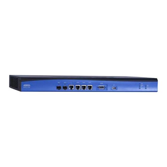
Physical Description NetVanta 6360 Hardware Installation Guide NetVanta 6360 Front Panel Design The NetVanta 6360 front panel is shown below along with a description of all connectors and interfaces. CONSOLE STATUS MODULE VOICE T1/E1 1 NetVanta 6360 T1/E1 2 Figure 2. NetVanta 6360 Front Panel Layout 10/100/1000Base-T Ethernet Interfaces port consists of one SFP slot for connectivity over fiber. -
Page 19: Table 1. Front Panel Status Led Behaviors
NetVanta 6360 Hardware Installation Guide Physical Description Table 1. Front Panel Status LED Behaviors Color Indication GIG 0/1/GIG 0/2 The link is down, shut, or not connected. (SFP) Green (solid) The link is up. Amber (flashing) There is transmit or receiver activity on the link. -
Page 20: Netvanta 6360 Rear Panel Design
Physical Description NetVanta 6360 Hardware Installation Guide NetVanta 6360 Rear Panel Design The NetVanta 6360 rear panel is shown below along with a description of all connectors and interfaces. VOICE AC INPUT T1/E1 0/1 T1/E1 0/2 RTN -48V DC IN Figure 3. -
Page 21: Features And Specifications
NetVanta 6360 Hardware Installation Guide Features and Specifications FEATURES AND SPECIFICATIONS Physical Interfaces Modular WAN Options • Carrier Ethernet Quad SHDSL, Annex A and B • Carrier Ethernet Octal SHDSL, Annex A and B • Carrier Ethernet Quad VDSL2, Annex A and B Gigabit Ethernet •... -
Page 22: Security
Features and Specifications NetVanta 6360 Hardware Installation Guide LEDs • Status • Module • • • Voice • T1/E1 1 • T1/E1 2 Layer 3 Quality of Service (QoS) • Low Latency Queuing, Weighted Fair Queuing (WFQ), and Class-based WFQ •... -
Page 23: Dsl Features
NetVanta 6360 Hardware Installation Guide Features and Specifications DSL Features • Variable rate bonding for the SHDSL loops • Automatic failover and recovery • Plug-and-play automatic line detection • ITU-G.991.2-2003, SHDSL Annex B Ethernet Features • IEEE 802.1p priority marking •... -
Page 24: Agency Approvals
Features and Specifications NetVanta 6360 Hardware Installation Guide Agency Approvals • FCC Part 15, Class A • UL 60950-1, Second Edition • EN 60950, Second Edition, A1, A11, A12 • IEC 60950-1, Second Edition • AS/NZS 60950.1 • CSA C22.2 No. 60950-1, Second Edition •... -
Page 25: Option Modules
Option Modules OPTION MODULES The NetVanta 6360 supports several option modules designed to meet a variety of networking requirements. The option modules include plug-in carrier Ethernet network modules. Carrier Ethernet network modules are cards that plug directly into the option module slot located on the front of the base unit. -
Page 26: Network Modules
Option Modules NetVanta 6360 Hardware Installation Guide Network Modules NetVanta Carrier Ethernet Quad SHDSL EFM Module, Annex A (P/N 17406368F1) The NetVanta Carrier Ethernet Quad SHDSL EFM Module, Annex A (shown in Figure 4) provides a WAN-SHDSL EFM interface. See Table A-6 on page 44 for the Quad SHDSL EFM connector pinouts. -
Page 27: Figure 5. Netvanta Carrier Ethernet Quad Shdsl Efm Module, Annex B
NetVanta 6360 Hardware Installation Guide Option Modules NetVanta Carrier Ethernet Quad SHDSL EFM Module, Annex B (P/N 17406368F3) The NetVanta Carrier Ethernet Quad SHDSL EFM Module, Annex B (shown in Figure 5) provides a WAN-SHDSL EFM interface. See Table A-6 on page 44 for the Quad SHDSL EFM connector pinouts. -
Page 28: Figure 6. Netvanta Carrier Ethernet Octal Shdsl Efm Module, Annex A
Option Modules NetVanta 6360 Hardware Installation Guide NetVanta Carrier Ethernet Octal SHDSL EFM Module, Annex A (P/N 17806368F1) The NetVanta Carrier Ethernet Octal SHDSL EFM Module, Annex A (shown in Figure 6) provides a WAN-SHDSL EFM interface. See Table A-7 on page 44... -
Page 29: Figure 7. Netvanta Carrier Ethernet Octal Shdsl Efm Module, Annex B
NetVanta 6360 Hardware Installation Guide Option Modules NetVanta Carrier Ethernet Octal SHDSL EFM Module, Annex B (P/N 17806368F3) The NetVanta Carrier Ethernet Octal SHDSL EFM Module, Annex B (shown in Figure 7) provides a WAN-SHDSL EFM interface. See Table A-7 on page 44... -
Page 30: Figure 8. Netvanta Carrier Ethernet Quad Vdsl2 Efm Module, Annex A
Option Modules NetVanta 6360 Hardware Installation Guide NetVanta Carrier Ethernet Quad VDSL2 EFM Module, Annex A (P/N 17406369F1) The NetVanta Carrier Ethernet Quad VDSL2 EFM Module, Annex A (shown in Figure 8) provides a WAN-VDSL interface. See Table A-9 on page 45 for the Quad VDSL2 connector pinouts. -
Page 31: Figure 9. Netvanta Carrier Ethernet Quad Vdsl2 Efm Module, Annex B
NetVanta 6360 Hardware Installation Guide Option Modules NetVanta Carrier Ethernet Quad VDSL2 EFM Module, Annex B (P/N 17406369F3) The NetVanta Carrier Ethernet Quad VDSL2 EFM Module, Annex B (shown in Figure 9) provides a WAN-VDSL interface. See Table A-9 on page 45 for the Quad VDSL2 connector pinouts. -
Page 32: Unit Installation
ADTRAN unit to Ethernet cables that run outside the building, ADTRAN's Ethernet Port Protection Device (EPPD) (P/N 1700502G1) must be connected between the unit and the outside plant cable. Use of any Ethernet protector other than ADTRAN's for this purpose will void the user's warranty. -
Page 33: Mounting Options
NetVanta 6360 Hardware Installation Guide Unit Installation Mounting Options The unit may be installed in rackmount or tabletop configurations. The following sections provide step-by-step instructions for rack mounting and wall mounting. Rack Mounting the NetVanta The NetVanta is a 1U-high, rack-mountable unit that can be installed in a 19-inch, 23-inch, or ETSI equipment rack. -
Page 34: Supplying Power To The Unit
NetVanta 6360 Hardware Installation Guide Supplying Power to the Unit The NetVanta 6360 can be powered with either a 110 to 240 VAC or a 48 VDC power source. Instructions for AC and DC powering are provided in the following sections. -
Page 35: Figure 10. Supplying Dc Power And Grounding The Netvanta 6360
NetVanta 6360 Hardware Installation Guide Unit Installation • Power to the NetVanta 6360 system must be from a reliably grounded 48 VDC. • Use only copper conductors when making power connections. • Install unit in accordance with the requirements of NEC NFPA 70. -
Page 36: Optional Battery Backup Unit (P/N 1175044L1)
Optional Battery Backup Unit (P/N 1175044L1) The ADTRAN battery backup unit (BBU) is an optional device designed as a backup DC power supply for the NetVanta 6360. The BBU connects to the NetVanta 6360 through a 6-foot charge/discharge, 2-conductor wire with a keyed modular plug (included with the BBU). -
Page 37: Figure 11. Wall Mounting The Bbu
NetVanta 6360 Hardware Installation Guide Unit Installation Wall Mounting the BBU Figure 11 shows the BBU (P/N 1175044L1) mounting dimensions for the NetVanta 6360. Figure 11. Wall Mounting the BBU Install the BBU as follows: Instructions for Wall Mounting the BBU... -
Page 38: Installing Network Modules
To order replacement batteries, reference the following part number: 1975044L1 (12 VDC replacement batteries). ADTRAN is an environmentally friendly company. Therefore, we encourage the proper recycling and handling of the batteries. Federal and state laws prohibit the improper disposal of all lead acid batteries. The customer is responsible for the handling of their batteries from the day of purchase through their ultimate disposal. -
Page 39: Figure 12. Network Module Installation
NetVanta 6360 Hardware Installation Guide Unit Installation For NetVanta modules with outside plant connections, ensure that all cables are removed from the module before installing or removing it from the NetVanta chassis. • Electronic modules can be damaged by static electrical discharge. Before handling modules, put on an antistatic discharge wrist strap to prevent damage to electrical components. - Page 40 Unit Installation NetVanta 6360 Hardware Installation Guide Copyright © 2014 ADTRAN, Inc. 617006364F1-34A...
-
Page 41: Appendix A. Connector Pin Definitions
Clear to Send (output) — Unused Table A-2. SFP Slot Pinouts Name Name TGND RGND TX FAULT TX DISABLE MOD DEF(2) RGND MOD DEF(1) VccR MOD DEF(0) VccT RATE SELECT TGND RGND RGND TGND 617006364F1-34A Copyright © 2014 ADTRAN, Inc. -
Page 42: Table A-3. 1000Base-T Gigabit Ethernet Port Pinouts
Appendix A NetVanta 6360 Hardware Installation Guide Table A-3. 1000Base-T Gigabit Ethernet Port Pinouts Name Description TRD0+ Transmit/Receive Positive TRD0- Transmit/Receive Negative TRD1+ Transmit/Receive Positive TRD2+ Transmit/Receive Positive TRD2- Transmit/Receive Negative TRD1- Transmit/Receive Negative TRD3+ Transmit/Receive Positive TRD3- Transmit/Receive Negative Table A-4. -
Page 43: Table A-5. Voice Connector Pinouts
NetVanta 6360 Hardware Installation Guide Appendix A Table A-5. Voice Connector Pinouts 50-pin Pins Amphenol Description Connector 1, 26 Circuit 1 FXS 0/1 Ring, Tip 2, 27 Circuit 2 FXS 0/2 Ring, Tip 3, 28 Circuit 3 FXS 0/3 Ring, Tip... -
Page 44: Network Module Pinouts
Appendix A NetVanta 6360 Hardware Installation Guide Network Module Pinouts Table A-6. Carrier Ethernet Quad SHDSL EFM Pinouts Ports 1 and 2 Ports 3 and 4 Name Description Name Description Loop 2 - Tip Loop 4 - Tip Loop 2 - Ring Loop 4 - Ring —... -
Page 45: Table A-9. Carrier Ethernet Quad Vdsl2 Efm Pinouts
NetVanta 6360 Hardware Installation Guide Appendix A Table A-9. Carrier Ethernet Quad VDSL2 EFM Pinouts Name Description 1, 2 — Unused Ring Ring lead of the 2-wire interface Tip lead of the 2-wire interface 5, 6 — Unused 617006364F1-34A Copyright © 2014 ADTRAN, Inc. - Page 46 Appendix A NetVanta 6360 Hardware Installation Guide Copyright © 2014 ADTRAN, Inc. 617006364F1-34A...