Table of Contents
Advertisement
Quick Links
4
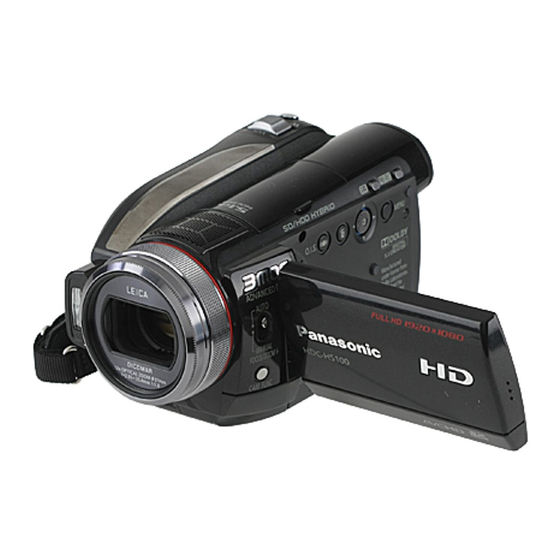
High Definition Video Camera
HDC-HS100P
Model No.
HDC-HS100PC
HDC-HS100PL
HDC-HS100E
HDC-HS100EB
HDC-HS100EE
HDC-HS100EF
HDC-HS100EG
HDC-HS100EP
HDC-HS100GC
HDC-HS100GK
HDC-HS100GN
HDC-HS100GT
HDC-HS100SG
Vol. 1
Colour
(K)...........Black Type
© 2008 Matsushita Electric Industrial Co., Ltd. All
rights reserved. Unauthorized copying and distribu-
tion is a violation of law.
ORDER NO. VM0808035CE
B27
Advertisement
Chapters
Table of Contents

Related Manuals for Panasonic HDC-HS100P


Summary of Contents for Panasonic HDC-HS100P
- Page 1 ORDER NO. VM0808035CE High Definition Video Camera HDC-HS100P Model No. HDC-HS100PC HDC-HS100PL HDC-HS100E HDC-HS100EB HDC-HS100EE HDC-HS100EF HDC-HS100EG HDC-HS100EP HDC-HS100GC HDC-HS100GK HDC-HS100GN HDC-HS100GT HDC-HS100SG Vol. 1 Colour (K)...Black Type © 2008 Matsushita Electric Industrial Co., Ltd. All rights reserved. Unauthorized copying and distribu-...
-
Page 2: Table Of Contents
TABLE OF CONTENTS PAGE PAGE 1 Safety Precaution -------------------------------------------------3 1.1. General Guidelines ----------------------------------------3 1.2. Leakage Current Cold Check ---------------------------3 1.3. Leakage Current Hot Check (See Figure 1.)--------3 1.4. How to Discharge the Capacitor on Flash PCB------------------------------------------------------------4 2 Warning --------------------------------------------------------------5 2.1. Prevention of Electrostatic Discharge (ESD) to Electrostatically Sensitive (ES) Devices ----------5 2.2. -
Page 3: Safety Precaution
1 Safety Precaution 1.1. General Guidelines 1.3. Leakage Current Hot Check 1. IMPORTANT SAFETY NOTICE (See Figure 1.) There are special components used in this equipment 1. Plug the AC cord directly into the AC outlet. Do not use which are important for safety. These parts are marked by an isolation transformer for this check. -
Page 4: How To Discharge The Capacitor On Flash Pcb
1.4. How to Discharge the Capacitor on Flash PCB CAUTION: 1. Be sure to discharge the capacitor on FLASH PCB. 2. Be careful of the high voltage circuit on FLASH PCB when servicing. [Discharging Procedure] 1. Refer to the disassemble procedure and Remove the necessary parts/unit. 2. -
Page 5: Warning
2 Warning 2.1. Prevention of Electrostatic Discharge (ESD) to Electrostatically Sensitive (ES) Devices Some semiconductor (solid state) devices can be damaged easily by static electricity. Such components commonly are called Elec- trostatically Sensitive (ES) Devices. Examples of typical ES devices are integrated circuits and some field-effect transistors and semiconductor "chip"... -
Page 6: Caution For Ac Cord (For Eb/Gc
2.3.2.3. How to Replace the Fuse A replacement fuse cover can be purchased from your local Panasonic Dealer. 1. Remove the Fuse Cover with a screwdriver. If the fitted moulded plug is unsuitable for the socket outlet in your home then the fuse should be removed and the plug cut off and disposed of safety. -
Page 7: How To Replace The Lithium Battery
2.4. How to Replace the Lithium Battery 2.4.1. Replacement Procedure 1. Remove the Power FPC. (Refer to Disassembly Procedures.) 2. Remove the Lithium battery (Ref. No. “B6701” at foil side of Power FPC) and then replace it into new one. NOTE: This Lithium battery is a critical component. -
Page 8: Service Navigation
When a part replacement is required for repairing MAIN PCB, replace as an assembled parts. (Main PCB) 2. The following category is /are recycle module part. Please send it/them to Central Repair Center. • MAIN PCB (VEP03H54H : HDC-HS100P/PC/PL) • MAIN PCB (VEP03H54J : HDC-HS100E/EF/EG) •... -
Page 9: How To Define The Model Suffix (Ntsc Or Pal Model)
3.4. How to Define the Model Suffix (NTSC or PAL model) There are six kinds of HDC-HS100. • a) HDC-HS100S • b) HDC-HS100P • c) HDC-HS100PC • d) HDC-HS100E/EB/EF/EG/EP/GN • e) HDC-HS100EE • c) HDC-HS100PL/GC/GK/GT/SG (HDC-HS100S is exclusively Japan domestic model.) What is the difference is that the “INITIAL SETTING”... -
Page 10: Precautions For Handling Hdd
3.5. Precautions for Handling HDD 1. Handle HDD very carefully to prevent the static electricity and shock. 2. Set the HDD quickly after taking it out from the package. Make sure to put the HDD on buffer materials, etc. 3.5.1. Precautions at incoming process and for opening packages... - Page 11 3.5.2. Precautions for installing HDD...
- Page 12 3.5.3. Precautions for inserting and removing HDD FPC Make sure to use the tool (LSVQ0112) when locking and unlocking the lock lever of HDD FPC connector. Do not lock the lock lever without inserting HDD FPC. Otherwise, the connector may be damaged.
-
Page 13: Formatting Hdd
Make sure to use the tool (LSVQ0112) when opening and closing the lock lever. When install the HDD to main unit, necessary install the HDD FPC and HDD cushion. 3.6. Formatting HDD When HDD is exchanged, format HDD as the procedure below... -
Page 14: Specifications
4 Specifications... -
Page 16: Location Of Controls And Components
5 Location of Controls and Components... -
Page 21: Service Mode
6 Service Mode 1. Indication method of the service menu Set the mode dial “HDD Recording” mode. 2. While keep pressing the “[LEFT<] of cursor” button and “delete” button, hold down the Mode Select Switch towards to “[FOCUS]” position for more than 3 seconds until the top screen of the Service Menu being displayed. Service mode menu Screen display Contents... -
Page 22: Drive Information Display
6.1. Drive Information Display 1. Set the mode dial “HDD Recording” mode. 2. While keep pressing the “[LEFT<] of cursor” button and “delete” button, hold down the Mode Select Switch towards to “[FOCUS]” position for more than 3 seconds until the top screen of the Service Menu being displayed. 3. -
Page 23: Lock Search History Indication
6.2. Lock Search History Indication 1. Set the mode dial “HDD Recording” mode. 2. While keep pressing the “[LEFT<] of cursor” button and “delete” button, hold down the Mode Select Switch towards to “[FOCUS]” position for more than 3 seconds until the top screen of the Service Menu being displayed. 3. -
Page 24: Hdd Self Check
6.3. HDD Self Check 1. Set the mode dial “HDD Recording” mode. 2. While keep pressing the “[LEFT<] of cursor” button and “delete” button, hold down the Mode Select Switch towards to “[FOCUS]” position for more than 3 seconds until the top screen of the Service Menu being displayed. 3. -
Page 25: Hdd Hardware Test
6.4. HDD Hardware Test 1. Set the mode dial “HDD Recording” mode. 2. While keep pressing the “[LEFT<] of cursor” button and “delete” button, hold down the Mode Select Switch towards to “[FOCUS]” position for more than 3 seconds until the top screen of the Service Menu being displayed. 3. -
Page 26: Service Fixture & Tools
7 Service Fixture & Tools 7.1. When Replacing the Main PCB After replacing the MAIN PCB, be sure to achieve adjustment. The adjustment instruction is available at “software download” on the “Support Information from NWBG/VDBG-PAVC” web-site in “TSN system”, together with Maintenance software. 7.2. - Page 27 CAUTION-1. (When servicing FLASH PCB) 1. Be sure to discharge the capacitor on FLASH PCB. Refer to “HOW TO DISCHARGE THE CAPACITOR ON FLASH PCB”. The capacitor voltage is not lowered soon even if the AC Cord is unplugged or the battery is removed. 2.
-
Page 28: Disassembly And Assembly Instructions
8 Disassembly and Assembly Instructions 8.1. Disassembly Flow Chart 8.2. PCB Location... -
Page 29: Disassembly Procedure
8.3. Disassembly Procedure Item Removal Speaker (Fig. D17) 2 Screws (V) Item Removal CAM FUNC OP P.C.B. (Fig. D18) 2 Screws (W) Lens Hood (Fig. D1) Lens Hood Speaker Angle Side Case (R) Unit (Fig. D2) 7 Screws (A) Hinge Reinforcement Plate 1 Screw (B) Speaker 3 Screws (C) - Page 30 8.3.1. Removal of the Lens Hood Item Removal Top Piece (Fig. D35) 2 Screws (j) Grip Frame Top Piece MOS Unit, (Fig. D36) 1 Screw (k) Optical Filter Lens Radiation Plate B Lens Radiation Plate A 2 Screws (l) MOS Unit Optical Filter 1st Lens Frame Unit (Fig.
- Page 31 8.3.2. Removal of the Side Case (R) Unit (Fig. D3) 8.3.3. Removal of the Side Case (L) Unit (Fig. D4) (Fig. D2)
- Page 32 8.3.4. Removal of the HDD Unit (Fig. D5) (Fig. D6)
- Page 33 8.3.5. Removal of the Top Case Unit 8.3.6. Removal of the Front Case Unit (Fig. D8) (Fig. D7)
- Page 34 8.3.7. Removal of the Battery Case Unit 8.3.8. Removal of the Lens Unit (Fig. D10) (Fig. D9)
- Page 35 8.3.9. Removal of the Lens Frame Unit 8.3.11. Removal of the Sub P.C.B. (Fig. D11) 8.3.10. Removal of the Main P.C.B. (Fig. D13) (Fig. D12)
- Page 36 8.3.12. Removal of the Flash P.C.B. (Fig. D15) (Fig. D14)
- Page 37 8.3.13. Removal of the Side (R) P.C.B. (Fig. D16) 8.3.14. Removal of the Speaker and CAM FUNC OP P.C.B. (Fig. D18) 8.3.15. Removal of the LCD Unit (Fig. D17) (Fig. D19)
- Page 38 (Fig. D20) 8.3.16. Removal of the Monitor P.C.B. (Fig. D22) (Fig. D21)
- Page 39 8.3.17. Removal of the LCD 8.3.18. Removal of the Mic P.C.B. (Fig. D24) (Fig. D23)
- Page 40 8.3.19. Removal of the Barrier Motor Unit and MF Unit (Fig. D25) (Fig. D26)
- Page 41 8.3.20. Removal of the Mic/Mic Damper 8.3.21. Removal of the Power FPC Unit (Fig. D28) (Fig. D27)
- Page 42 8.3.23. Removal of the EVF Unit (Fig. D29) 8.3.22. Removal of the Battery Lock Knob and Battery Lock Spring (Fig. D31) (Fig. D30)
- Page 43 8.3.24. Removal of the Rear Operation Unit and Top Operation Unit (Fig. D34) 8.3.26. Removal of the Top Piece (Fig. D32) 8.3.25. Removal of the Shoe Cover and Shoe Angle (Fig. D35) (Fig. D33)
- Page 44 8.3.27. Removal of the MOS Unit and 8.3.28. Removal of the 1st Lens Frame Unit Optical Filter (Fig. D37) 8.3.29. Removal of the Zoom Motor Unit (Fig. D36) (Fig. D38)
- Page 45 (Fig. D41) (Fig. D39) 8.3.30. Removal of the IRIS Unit (Fig. D40)
- Page 46 8.3.31. Removal of the Main Frame and 8.3.33. Removal of the OIS Frame Unit and 2nd Lens Frame Move Unit Guide Pole S (Fig. D44) 8.3.34. Removal of the Guide Pole L, 4th Lens Frame Move Unit and Master Frange (Fig.
-
Page 47: Measurements And Adjustments
9 Measurements and Adjustments 9.1. Electric Adjustment • Adjustment method is different from a conventional SD video camera. • An exclusive jig and PC (including software for adjustment “Tatsujin”) are necessary for electric adjustment. • A USB driver for service is necessary to communication with PC. •... - Page 48 Adjustment Items • Adjustment item as follows. The adjustment instruction is available at "Software download" on the "Support Information from NWBG/VDBG-PAVC" web-site in "TSN System".
-
Page 49: Factory Setting
10 Factory Setting 10.1. HOW TO TURN ON THE FACTORY SETTINGS? 1. Set the mode dial “HDD Recording” mode. 2. While keep pressing the “[LEFT<] of cursor” button and “delete” button, hold down the Mode Select Switch towards to “[FOCUS]” position for more than 3 seconds until the top screen of the Service Menu being displayed. 3. - Page 50 3.The voltage being indicated on the schematic diagram is measured in "Standard-Playback" mode when there is no specify mode is mentioned. Model No. HDC-HS100P HDC-HS100EG 4.Although the voltage and waveform available on here is measured with standard frame, it may be differ from actual measurement due to modification of circuit and so on.
-
Page 51: S2. Voltage Chart
S2. Voltage Chart Note) Indicated voltage values are the standard values for the unit measured by the DC electronic circuit tester (high-impedance) with the chassis taken as standard. Therefore, there may exist some errors in the voltage values, depending on the internal impedance of the DC circuit tester. S2.1. -
Page 52: S3. Block Diagram
S3. Block Diagram S3.1. Overall Block Diagram IC601 COLOR LCD PANEL DRIVER LENS(F1.8 x 12) IC801 ZOOM/ 3MOS IRIS/ FOCUS DRIVER MOTOR A/V OUT IC3601 D TERMINAL IC101,103,106 VIDEO CDS/PGA&10bit ADC ENCODER IC3701 ( 2ch) AVIO IC4801-4803 MIC AMP SPEAKER X301 IC301 IC3400... -
Page 53: S4. Schematic Diagram
S4. Schematic Diagram S4.1. Interconnection Diagram MIC FPC DRIVE FPC FP6401 MIC P.C.B. FP6402 (COMPONENT MAIN P.C.B. SIDE) (FOIL SIDE) (FOIL SIDE) (COMPONENT SIDE) FP4803 MFL1 FLASH P.C.B. MFVCC MFL2 MFVCC (COMPONENT SIDE) MFLED SE GND REAR OPERATION UNIT MF SENSOR ECM FPC FP6003 MOTER P... -
Page 54: S4.2. Flash Schematic Diagram
S4.2. Flash Schematic Diagram / S4.3. CAM FUNC OP Schematic Diagram HDC-HS100 Series HDC-HS100 Series Flash CAM FUNC OP Schematic Diagram Schematic Diagram... -
Page 55: S4.4. Monitor Schematic Diagram
S4.4. Monitor Schematic Diagram HDC-HS100 Series Monitor Schematic Diagram... -
Page 56: S4.5. Side R Schematic Diagram
S4.5. Side R Schematic Diagram HDC-HS100 Series Side R Section (Side R P.C.B. (1/2)) Schematic Diagram... -
Page 57: S4.6. Lcd Schematic Diagram
S4.6. LCD Schematic Diagram HDC-HS100 Series LCD Section (Side R P.C.B. (2/2)) Schematic Diagram... -
Page 58: S4.7. Evf B/L Schematic Diagram
S4.7. EVF B/L Schematic Diagram HDC-HS100 Series EVF B/L Schematic Diagram... -
Page 59: S4.8. Mic Schematic Diagram
S4.8. Mic Schematic Diagram HDC-HS100 Series Schematic Diagram S-10... -
Page 60: S4.9. Power Fpc Schematic Diagram
S4.9. Power FPC Schematic Diagram HDC-HS100 Series Power FPC Schematic Diagram S-11... -
Page 61: S4.10. Main Sub Fpc Schematic Diagram
S4.10. Main Sub FPC Schematic Diagram HDC-HS100 Series Main Sub FPC Schematic Diagram S-12... -
Page 62: S4.11. Side R Fpc Schematic Diagram
S4.11. Side R FPC Schematic Diagram / S4.12. Monitor FPC Schematic Diagram HDC-HS100 Series HDC-HS100 Series Side R FPC Monitor FPC Schematic Diagram Schematic Diagram S-13... -
Page 63: S4.13. Mos Fpc Schematic Diagram
S4.13. MOS FPC Schematic Diagram HDC-HS100 Series MOS FPC Schematic Diagram S-14 S-14... - Page 64 HDC-HS100 Series MOS FPC Schematic Diagram S-15 S-15...
- Page 65 HDC-HS100 Series MOS FPC Schematic Diagram S-16...
- Page 66 HDC-HS100 Series MOS FPC Schematic Diagram S-17...
-
Page 67: S4.14. Mf Sensor Fpc Schematic Diagram
S4.14. MF Sensor FPC Schematic Diagram HDC-HS100 Series MF Sensor FPC Schematic Diagram S-18... -
Page 68: S5. Print Circuit Board
S5. Print Circuit Board S5.1. Flash P.C.B. S5.1.1. Flash P.C.B. (Component Side) (Component Side) HDC-HS100 Series Flash P.C.B. (Component Side) S-19... -
Page 69: S5.1.2. Flash P.c.b. (Foil Side
S5.1.2. Flash P.C.B. (Foil Side) (Foil Side) HDC-HS100 Series Flash P.C.B. (Foil Side) S-20... -
Page 70: S5.2. Cam Func Op P.c.b
S5.2. CAM FUNC OP P.C.B. (Component Side) (Component Side) (Foil Side) (Foil Side) HDC-HS100 Series HDC-HS100 Series CAM FUNC OP P.C.B. CAM FUNC OP P.C.B. S-21... -
Page 71: S5.3. Monitor P.c.b
S5.3. Monitor P.C.B. (Component Side) (Foil Side) HDC-HS100 Series Monitor P.C.B. S-22... -
Page 72: S5.4. Side R P.c.b
S5.4. Side R P.C.B. (Component Side) (Foil Side) HDC-HS100 Series Side R P.C.B. S-23... -
Page 73: S5.5. Evf B/L P.c.b
S5.5. EVF B/L P.C.B. / S5.6. Mic P.C.B. (Component Side) (Component Side) (Foil Side) (Foil Side) HDC-HS100 Series HDC-HS100 Series EVF B/L P.C.B. Mic P.C.B. S-24... -
Page 74: S5.7. Power Fpc P.c.b
S5.7. Power FPC P.C.B. (Component Side) (Foil Side) HDC-HS100 Series Power FPC P.C.B. S-25... -
Page 75: S5.8. Main Sub Fpc P.c.b
S5.8. Main Sub FPC P.C.B. / S5.9. Side R FPC P.C.B. (Component Side) (Foil Side) (Foil Side) HDC-HS100 Series HDC-HS100 Series Main Sub FPC P.C.B. Side R FPC P.C.B. S-26... -
Page 76: S5.10. Monitor Fpc P.c.b
S5.10. Monitor FPC P.C.B. (Foil Side) HDC-HS100 Series Monitor FPC P.C.B. S-27... -
Page 77: S5.11. Mos Fpc P.c.b
S5.11. MOS FPC P.C.B. (Component Side) (Foil Side) HDC-HS100 Series MOS FPC P.C.B. S-28... -
Page 78: S5.12. Mf Sensor Fpc P.c.b
S5.12. MF Sensor FPC P.C.B. (Component Side) (Foil Side) HDC-HS100 Series MF Sensor FPC P.C.B. S-29... - Page 79 S-30...
-
Page 80: S6. Replacement Parts List
S6. Replacement Parts List Note: 1.* Be sure to make your orders of replacement parts according to this list. 2. IMPORTANT SAFETY NOTICE Components identified with the mark have the special characteristics for safety. When replacing any of these components, use only the same type. 3. - Page 81 HDC-HS100P-K,PCK,PLK,E-K,EBK,EEK,EFK,EGK,EPK,GCK,GKK,GNK,GTK,SGK Ref.No. Part No. Part Name & Description Remarks Ref.No. Part No. Part Name & Description Remarks VEP03H54H MAIN P.C.B. 1 (RTL) E.S.D.(P,PC,PL) VEP20C33A CAM FUNC OP PCB (RTL) E.S.D. VEP03H54J MAIN P.C.B. 1 (RTL) E.S.D.(E,EF,EG) VEP03H54V MAIN P.C.B. 1 (RTL) E.S.D.(EB)
- Page 82 HDC-HS100P-K,PCK,PLK,E-K,EBK,EEK,EFK,EGK,EPK,GCK,GKK,GNK,GTK,SGK Ref.No. Part No. Part Name & Description Remarks Ref.No. Part No. Part Name & Description Remarks R801 ERJ2GEJ472 M.RESISTOR CH 1/16W 4.7K VEP24193A MIC P.C.B. (RTL) E.S.D. R803 ERJ2RHD511 M.RESISTOR CH 1/16W 510 R804 ERJ2RHD102X RESISTOR C4801 ECJ0EB1A473K C.CAPACITOR CH 10V 0.047U...
- Page 83 HDC-HS100P-K,PCK,PLK,E-K,EBK,EEK,EFK,EGK,EPK,GCK,GKK,GNK,GTK,SGK Ref.No. Part No. Part Name & Description Remarks Ref.No. Part No. Part Name & Description Remarks VGQ9149 LCD HOLD PIECE VYK2R79 R COVER UNIT VGU0C99 VIEW ANGLE ADJUSTER KNOB VYK2S80 CROSS KEY UNIT VYQ4404 LENS HOOD UNIT XQN16+B4FJK SCREW...
- Page 84 HDC-HS100P-K,PCK,PLK,E-K,EBK,EEK,EFK,EGK,EPK,GCK,GKK,GNK,GTK,SGK Ref.No. Part No. Part Name & Description Remarks Ref.No. Part No. Part Name & Description Remarks VGQ0B66 EARTH PLATE VSC6057 LENS RADIATION PLATE VGQ0B29 LENS BARRIER VYK2R63 MAIN FRAME UNIT VEP21302A MAIN - SUB FPC VEP01A13B SUB P.C.B. 1 (RTL) E.S.D.
- Page 85 HDC-HS100P-K,PCK,PLK,E-K,EBK,EEK,EFK,EGK,EPK,GCK,GKK,GNK,GTK,SGK Ref.No. Part No. Part Name & Description Remarks Ref.No. Part No. Part Name & Description Remarks VYK2T28 LCD CASE(T) UNIT VSC6003 LCD EARTH PLATE VEP26320A MONITOR PCB 1 (RTL) E.S.D. VGL1255 DIFFUSION SHEET VKW3365 LIGHTING PLATE VGL1256 REFLECTION SHEET...
- Page 86 HDC-HS100P-K,PCK,PLK,E-K,EBK,EEK,EFK,EGK,EPK,GCK,GKK,GNK,GTK,SGK Ref.No. Part No. Part Name & Description Remarks Ref.No. Part No. Part Name & Description Remarks VXQ1614 MOS UNIT 201-1 VEP22394A MOS FPC 1 E.S.D. VXW0974 LENS UNIT VXQ1609 1ST LENS UNIT VDW1689 MAIN UNIT VXP2992 2ND LENS MOVING FRAME UNIT...
- Page 87 HDC-HS100P-K,PCK,PLK,E-K,EBK,EEK,EFK,EGK,EPK,GCK,GKK,GNK,GTK,SGK Ref.No. Part No. Part Name & Description Remarks Ref.No. Part No. Part Name & Description Remarks VPF1228 POLYETHYLENE BAG 1 (E,EG,EP,GC,SG) K2KZ9DB00004 COMPONENT CABLE VPF1112 POLYETHYLENE BAG 1 (P,PC,PL,EB,EE, 302 K2CQ2CA00006 AC CABLE 1 (E,EE,EF,EG,EP,GC,SG) EF,GK,GN,GT) VPG1T69 PACKING CASE 1 (P,PC) ...
-
Page 88: S7. Exploded View
S7. Exploded View S7.1. Frame and Casing Section (1) B171 B2 B3 74 73 S-39... -
Page 89: S7.2. Frame And Casing Section (2
S7.2. Frame and Casing Section (2) S-40... -
Page 90: S7.3. Lcd Section
S7.3. LCD Section B151 B152 S-41... -
Page 91: S7.4. Camera Lens Section
S7.4. Camera Lens Section B205 B204 B201 B212 201-1 B202 B210 B209 B206 B213 B203 B214 B207 B208 S-42... -
Page 92: S7.5. Packing Parts And Accessories Section
S7.5. Packing Parts and Accessories Section HDC-HS100 (HDC-HS100 GN) E/EE/EF/EG/EP/GC/SG HDC-HS100 P/PC/PL/GK/GT (HDC-HS100 EB/GC/SG) (HDC-HS100 GC/SG) S-43...