
Related Manuals for HP HSR6600 Series


Summary of Contents for HP HSR6600 Series
- Page 1 HP HSR6600 Routers Installation Guide 5998-3100 Part number: 5998-3100 Document version: 6PW105-20140210...
- Page 2 The only warranties for HP products and services are set forth in the express warranty statements accompanying such products and services. Nothing herein should be construed as constituting an additional warranty.
- Page 3 Contents Preparing for installation ············································································································································· 1 Safety recommendations ·················································································································································· 1 Safety symbols ·························································································································································· 1 General safety recommendations ··························································································································· 1 Electricity ··································································································································································· 2 Laser safety ································································································································································ 2 Router moving ··························································································································································· 2 Examining the installation site ········································································································································· 2 ...
- Page 4 Connecting an E1/T1 cable ································································································································ 26 Connecting a CE3/CT3 cable ····································································································································· 28 CE3/CT3 cable overview ···································································································································· 28 Connecting a CE3/CT3 cable ····························································································································· 28 Connecting a serial port cable ····································································································································· 29 Overview ································································································································································ 29 Connecting a serial port cable ···························································································································· 31 ...
- Page 5 Viewing the system fault solving method ············································································································ 58 Saving the current configuration of the router ············································································································ 58 Rebooting the router ······················································································································································ 58 Troubleshooting ·························································································································································· 60 Router failures ································································································································································· 60 Power status LEDs are off ······································································································································ 60 ...
- Page 6 Examples ········································································································································································· 95 Example 1 ······························································································································································ 95 Example 2 ······························································································································································ 95 Support and other resources ····································································································································· 97 Contacting HP ································································································································································ 97 Subscription service ·············································································································································· 97 Related information ························································································································································ 97 Documents ······························································································································································ 97 ...
- Page 7 Preparing for installation The HP HSR6600 Router Series is a line of high-performance centralized product, which includes the models in Table Table 1 Models for the HP HSR6600 Routers Product code Full name Abbreviation JG353A HP HSR6602-G Router BJNGA-BB0001 HSR6602-G...
- Page 8 Always check that the power has been disconnected. • Laser safety The HP HSR6600 routers are Class 1 laser devices. WARNING! Do not stare into any fiber port when the router has power. The laser light emitted from the optical fiber •...
- Page 9 Temperature and humidity Maintain appropriate temperature and humidity in the equipment room. • Lasting high relative humidity can cause poor insulation, electricity creepage, mechanical property change of materials, and metal corrosion. Lasting low relative humidity can cause washer contraction and ESD and bring problems including •...
- Page 10 The equipment room must also meet strict limits on salts, acids, and sulfides to eliminate corrosion and premature aging of components, as shown in Table Table 6 Harmful gas limits in an equipment room Max. (mg/m 0.006 0.05 0.01 Cooling system The HSR6600 routers adopt left to right airflow for heat dissipation.
- Page 11 Touch only the edges, instead of electronic components when observing or moving a removed • memory module, CF card, HIM, or MIM. To use the ESD-preventive wrist strap, perform the following steps: Wear the wrist strap on your wrist. Lock the wrist strap tight around your wrist to keep good contact with the skin. Attach the ESD-preventive wrist strap to the alligator clips.
- Page 12 NOTE: Use electromagnetic shielding when necessary. Lightning protection To protect the router from lightning better, do as follows: Make sure the chassis is well grounded. • • Make sure the grounding terminal of the AC power receptacle is well grounded. Install a lightning protector at the input end of the power supply to enhance lightning protection •...
- Page 13 Accessories 3 m (9.84 ft) Rear mounting Front mounting Load-bearing grounding cable bracket bracket and cable screw Console cable management bracket (supplied with router) (supplied with (supplied with (supplied with router) router) (supplied with router) router) ESD-preventive wrist Rubber feet M6 screw Cage nuts Cable tie...
- Page 14 Installing the router NOTE: The fan tray, power modules, FIPs, and interface modules are hot swappable. Installation flow Figure 3 HSR6600 installation flow Check before installation Follow these guidelines to prepare for installing an HSR6600 router: Make sure that you have read “Preparing for installation”...
- Page 15 IMPORTANT: To mount multiple devices in the rack, place the heaviest one at the bottom of the rack. Unpacking the router Unpack the router as shown in Figure Figure 4 Unpacking the router Foam brace Packing belt Installing the router in a 19-inch rack Before you install the router to a rack, wear an ESD-preventive wrist strap.
- Page 16 Figure 6 Installing cage nuts Install the cable management brackets. See Figure Figure 7 Installing the front mounting brackets and load-bearing screws Install the router to the rack. CAUTION: This task requires at least two people.
- Page 17 Figure 8 Installing the router to the rack Grounding the router Installing the ring terminal No ring terminal is supplied with the grounding cable. You must install one yourself. To install the ring terminal: Cut the grounding cable as appropriate for connecting to the grounding strip, and strip 5 mm (0.20 in) of insulation sheath by using a wire stripper.
- Page 18 Figure 9 Installing the ring terminal Grounding cable Ring terminal Insulation sheath Connecting the grounding cable Remove the grounding screw from the rear panel of the router chassis. Attach the grounding screw to the ring terminal of the grounding cable. Use a screwdriver to fasten the grounding screw into the grounding screw hole.
- Page 19 Installing a power module Before you install a power module, make sure the power switch is off and the router is well grounded. The procedures for installing an AC power module and a DC power module are the same. The following uses an AC power module as an example.
- Page 20 Fasten the captive screws on the FIP module with a Philips screwdriver. Figure 12 Installing a FIP module NOTE: For more information about the FIP LEDs, see “Appendix B LEDs.” Installing a HIM/MIM NOTE: • Install the MIM in the lower slot on the FIP module. Only the FIP-20 supports HIMs.
- Page 21 Figure 13 Installing the MIM Installing a CF card Press the spring clip at the right of the CF card cover to open it. Figure 14 Open the CF card cover Press the ejector button next to the CF card slot. Insert the CF card into the slot and make sure it does not project from the slot.
- Page 22 Figure 16 Close the CF card cover Connecting the power cord Connecting an AC power cord To connect an AC power cord: Make sure the router is well grounded, and the power switch on the router is in the OFF position. Pull the bail latch upwards.
- Page 23 Figure 18 Insert the plug Tighten the screws on the plug with a flat-blade screwdriver to secure the plug in the power receptacle. Figure 19 Tighten the screws Connect the two wires at the other end of the power cord to a DC power source.
- Page 24 Connecting the router to the network Connecting the AUX cable Overview An AUX console cable is an 8-core shielded cable, with a crimped RJ-45 connector at one end for connecting to the AUX port of the router, and DB-25 and DB-9 male connectors at the other end for connecting to the serial port of the modem.
- Page 25 Figure 21 Connecting the AUX port to a modem Connecting an Ethernet cable Overview 10/100 Mbps Ethernet uses category-5 twisted pair cables, while 1000 Mbps Ethernet uses category-5 enhanced or category-6 twisted pair cables. Twisted pair cables include straight-through cables and crossover cables.
- Page 26 Figure 22 RJ-45 connector pinout PIN #8 PIN #1 EIA/TIA cabling specifications define two standards, 568A and 568B, for cable pinouts. Standard 568A—Pin 1: white/green stripe, pin 2: green solid, pin 3: white/orange stripe, pin 4: • blue solid, pin 5: white/blue stripe, pin 6: orange solid, pin 7: white/brown stripe, pin 8: brown solid.
- Page 27 Pinout No. Brown/white Brown/white Brown Brown NOTE: Strictly follow the pinouts in the above tables when identifying or making the two types of Ethernet cables; otherwise, the communication quality may be affected. Making an Ethernet cable To make an Ethernet twisted pair cable: Cut the cable to a proper length with the crimping pliers.
- Page 28 Figure 23 SFP transceiver module Figure 24 XFP transceiver module Figure 25 SFP+ transceiver module Fiber cable overview You can use an optical fiber to connect a fiber Ethernet port or 10 Gbps Ethernet port. In addition, an optical fiber can connect these types of interface modules: HIM-4GBP/HIM-8GBP, HIM-CL1P/HIM-CL2P, HIM-CLS1P/HIM-CLS2P, HIM-MSP2P/HIM-MSP4P, HIM-PS1P, HIM-AL1P/HIM-AL2P, HIM-RS2P, or HIM- 1 EXP.
- Page 29 Table 9 Characteristics of single mode and multi-mode optical fibers Single mode fiber Multi-mode fiber Larger core than single mode fiber Core Small core (10 micrometers or less) (50 micrometers, 62.5 micrometers or greater) Allows greater dispersion and Dispersion Less dispersion therefore, signal loss exists.
- Page 30 The HSR6600 supports LC fiber cables only. • Some cards of the HP HSR6600 router provide shielded covers for the fiber ports (such as SFP ports). • Before using such fiber ports, remove the shielded covers. Keep the shielded covers properly. When the fiber ports are not in use, install the shielded covers.
- Page 31 Figure 27 Connecting a fiber cable Connecting an E1/T1 cable E1/T1 cable overview E1 cable You can use an 8E1 interface cable to connect to MIM-8E1(75)/MIM-8E1(75)-F modules. Figure 28 8E1 splitter cable NOTE: The coaxial connector and 75-ohm E1 adapter cable are optional accessories, and must be purchased separately if needed.
- Page 32 • insertion, which may damage the interface module or even the router. HP recommends that you install a lightning protector at the input end of the 8T1 cables to protect them • against lightning strikes more efficiently when they are led outdoors.
- Page 33 Figure 30 Connect an E1 75-ohm cable • If you want to extend the cable, connect each BNC connector of the E1 75-ohm cable to one end of a coaxial connector, and connect the remote device to the other end of the coaxial connector through an E1 75-ohm adapter cable.
- Page 34 You can use a CE3/CT3 interface cable to connect the MIM- 1 CE3 and MIM- 1 CT3 modules. Figure 34 E3/T3 cable CAUTION: HP recommends that you install a special lightning protector at the input end of the E3/T3 cables to protect them against lightning strikes more efficiently when they are routed outdoors. Connecting a CE3/CT3 cable Connect the SMB connector of an E3/T3 cable to the Tx port on the interface module and the other end to the Rx port on the device to be connected.
- Page 35 Figure 35 Connecting a CE3/CT3 cable Connecting a serial port cable Overview You can use a serial port cable to connect to the MIM-2SAE/MIM-4SAE/MIM-8SAE module. Select a serial port cable according to the link type. Figure 36 V.24 DTE cable Figure 37 V.24 DCE cable...
- Page 36 Figure 38 V.35 DTE cable Figure 39 V.35 DCE cable Pos.28 Pos.1 Figure 40 X.21 DTE cable Pos.1 Pos.1 Pos.15 Pos.28 Figure 41 X.21 DCE cable...
- Page 37 Figure 42 RS449 DTE cable Figure 43 RS449 DCE cable Figure 44 RS530 DTE cable Figure 45 RS530 DCE cable Connecting a serial port cable Check port type of the peer device and choose the synchronous serial interface cable of correct type.
- Page 38 Check the LINK LED on the SAE panel. If the LED is on, a link is present. If the LED is off, a fault has occurred on the link and signal is out of synchronization. In this case, check the link.
- Page 39 Logging in to the router and configuring basic settings Login methods The following login methods are available for you to log in to the router: • Logging in through the console port, which is the most common way to log in to a router and also the prerequisite for configuring other login methods.
- Page 40 Figure 46 Connecting the console cable CAUTION: To disconnect a PC from the router, disconnect the RJ-45 connector first. Setting terminal parameters To set terminal parameters, for example, on a Windows XP HyperTerminal: Select Start > All Programs > Accessories > Communications > HyperTerminal. The Connection Description dialog box appears.
- Page 41 Select the serial port to be used from the Connect using list, and click OK. Figure 48 Setting the serial port used by the HyperTerminal connection Set Bits per second to 9600, Data bits to 8, Parity to None, Stop bits to 1, and Flow control to None, and click OK.
- Page 42 Figure 50 HyperTerminal window On the Settings tab, set the emulation to VT100 and click OK. Figure 51 Setting terminal emulation in aaa Properties dialog box...
- Page 43 Powering on the router Power on the router, and you can see the following information: System is starting... Booting Normal Extend BootWare..**************************************************************************** HP HSR6600 Router BootWare, Version 1.01 **************************************************************************** Copyright (c) 2010-2012 Hewlett-Packard Development Company, L.P. Compiled Date : Nov 14 2011...
- Page 44 User interface con0 is available. Press ENTER to get started. Press Enter at the prompt and the prompt <HP> appears. You can now configure the router. Logging in to the router through Telnet/SSH To log in to the router through Telnet/SSH: Log in to the router through the console port.
- Page 45 Displaying the initial configuration After you log in to the router for the first time, use the display current-configuration command to display the initial configuration of the router. <HP>display current-configuration version 5.20, A2605 sysname HP domain default enable system domain system...
- Page 46 Step Command Remarks Enter system view system-view Available in user view interface interface-type Enter Ethernet interface view interface-number Specify an IP address for the ip address ip-address { mask-length By default, no IP address is interface | mask } [ sub ] assigned to any interface.
- Page 47 Replacement procedures Safety recommendations Always wear an ESD-preventive wrist strap or ESD-preventive gloves when replacing the modules. When operating a pluggable module, such as a FIP module, memory module, CF card, or HIM/MIM, follow these guidelines: Ensure good alignment with the slot to avoid damage to the module during installation or removal.
- Page 48 Replacing a FIP module CAUTION: When the RUN LED of the FIP module is fast flashing, do not unplug the FIP module. To replace a FIP module, for example, FIP-20: Determine the FIP module to be removed. This section takes the FIP module in slot 3 as an example. Use a Philips screwdriver to loosen the captive screws of the FIP module to be removed until all spring pressure is released.
- Page 49 Holding the handle of the MIM, gently pull the MIM out of slot along the slide rails. Figure 54 Pulling the MIM out of the slot If you do not install a new MIM in the slot, install a blank panel. To install a new MIM, see “Installing a HIM/MIM.”...
- Page 50 Figure 56 Pull the CF card To install a new MIM, see “Installing a CF card.” NOTE: To protect the CF card, place it into an antistatic bag. Replacing a transceiver module NOTE: When replacing a transceiver module, make sure that the two transceiver modules connected by the same optical fiber have the same wavelength.
- Page 51 Figure 57 Removing a transceiver module WARNING! • Do not stare into the optical fibers. When removing a transceiver module, do not touch the golden finger of the transceiver module. • Figure 58 Transceiver module golden finger Replacing a fan tray WARNING! Rotating fan blades can cause serious injury or cut.
- Page 52 Keep the tamper-proof seal on a mounting screw on the chassis cover intact, and if you want to open the • chassis, contact the local agent of HP for permission. Otherwise, HP shall not be liable for any consequence caused thereby.
- Page 53 Memory module structure Figure 60 Memory module structure (1) Connector edge (2) Polarization notch (3) Latch notch Figure 61 Memory module slot (1) Release latch (2) Memory module slot When to replace a memory module Memory modules are removable components of the router. You need to replace a memory module in the following situations: More memory is needed to upgrade the application program.
- Page 54 Figure 62 Opening the chassis cover Replacing a memory module Figure 63 Replacing a memory module CAUTION: Align the polarization notch of the memory module with the key in the connector when you insert a memory module.
- Page 55 Comware Software, Version 5.20.106, A2701 Copyright (c) 2010-2012 Hewlett-Packard Development Company, L.P. HP HSR6602 uptime is 0 week, 0 day, 0 hour, 1 minute Slot 0: HSR6602-XG uptime is 0 week, 0 day, 0 hour, 1 minute CPU type: FREESCALE P4080 1500MHz...
- Page 56 Displaying the operational statistics of the router When you perform routine maintenance or the system fails, you may need to view the operational information of each functional module for locating failures. Generally, you need to run display commands one by one. To collect more information one time, you can execute the display diagnostic-information command in any view to display or save the operational statistics of multiple functional modules of the router.
- Page 57 DEVICE_NAME:HSR6602-XG JG354A DEVICE_SERIAL_NUMBER:CN12FRX123 MAC_ADDRESS:000F-E123-4567 MANUFACTURING_DATE:2012-02-02 VENDOR_NAME:HP Slot 1: DEVICE_NAME:HP HSR6602-XG FIP-20 Flex Intf Pltfm Rtr Mod JG358A DEVICE_SERIAL_NUMBER:CN12FS1123 MAC_ADDRESS:NONE MANUFACTURING_DATE:2012-02-02 VENDOR_NAME:HP Use the display device manuinfo slot slot-number command to display the electrical label information of the module in the specified slot.
- Page 58 Table 12 Output description Field Description Slot 0 Router or interface module slot DEVICE_NAME Router or module type DEVICE_SERIAL_NUMBER Router or module serial number MAC address of the router or interface module: • An device has a MAC address. MAC_ADDRESS •...
- Page 59 Table 14 Output description Field Description System Total Memory(bytes) Physical memory size (in bytes) of the module Total Used Memory(bytes) Used memory size (in bytes) of the module Used Rate Memory usage of the module Displaying the CF card information Use the display device cf-card command to display the CF card information.
- Page 60 Displaying the operational status of power modules Use the display power command to display the operational status of power modules. <Sysname> display power Power 1 State: Absent Power 2 State: Normal Table 17 Output description Field Description Power Number of the power supply The power supply state: •...
- Page 61 GigabitEthernet0/0/2 current state: DOWN Line protocol current state: DOWN Description: GigabitEthernet0/0/2 Interface The Maximum Transmit Unit is 1500 Internet Address is 51.1.1.1/24 Primary IP Packet Frame Type: PKTFMT_ETHNT_2, Hardware Address: 000f-e200-0005 IPv6 Packet Frame Type: PKTFMT_ETHNT_2, Hardware Address: 000f-e200-0005 Media type is optical fiber, loopback not set, promiscuous mode not set 1000Mb/s, Full-duplex, link type is autonegotiation Output flow-control is disabled, input flow-control is disabled Output queue : (Urgent queuing : Size/Length/Discards)
- Page 62 0 crc, 0 align errors, 0 overruns 0 dribbles, 0 drops Output:0 packets, 0 bytes 0 broadcasts, 0 multicasts, 0 pauses 0 errors, 0 underruns, 0 collisions 0 deferred, 0 lost carriers Configuring a combo interface To configure a combo interface: Step Command Remarks...
- Page 63 The system outputs alarm information for you to locate and troubleshoot faults of transceiver modules. For the HP-customized transceiver modules, the system can also monitor the key parameters, such as temperature, voltage, laser bias current, TX power, and RX power. When these parameters are abnormal, you can take corresponding measures to prevent transceiver module faults.
- Page 64 Viewing the system fault solving method Use the display system-failure command to display the system fault solving method. <Sysname> display system-failure System failure handling method: reboot Saving the current configuration of the router You can save the current configuration of the router in one of the following methods: Fast saving—Executing the save command without the safely keyword.
- Page 65 To reboot the router immediately: Purpose Command Remarks Required Reboot the router immediately reboot Available in user view To enable the scheduled reboot function: Purpose Command Remarks Enable the scheduled reboot Use either command function and specify a specific schedule reboot at hh:mm [ date ] reboot time and date The scheduled reboot function is disabled by default.
- Page 66 Troubleshooting NOTE: The barcode stuck on the router chassis contains production and servicing information. Before you return a faulty router for serving, provide the barcode information of the router to your local sales agent. Router failures Power status LEDs are off When the PWR1 and PWR2 LEDs are off, the power module of the router is faulty.
- Page 67 When the system is over-temperature. In this case, the system displays the following output: • %Dec 7 11:17:01:436 2011 HP DRVMSG/3/TEMP_ALARM: CPU temperature is greater than alarm upper limit in slot 0, index is 0. To solve the problem, check the output (such as the system temperature, insufficient available power, and PCB voltage alarms) on the serial terminal and the software management tool.
- Page 68 Fan tray is absent After the router is booted, the following information may appear on the configuration terminal: #Dec 9 09:57:12:560 2011 HP DEVM/1/FAN STATE CHANGES TO FAILURE: Trap 1.3.6.1.4.1.25506.8.35.12.1.6: fan ID is 1 %Dec 9 09:57:12:560 2011 HP DEVM/3/FAN_ABSENT: Fan 1 is absent.
- Page 69 6 17:13:56:447 2011 HP DEVM/5/FAN_RECOVERED: Fan 1 recovered. %Dec 6 17:13:58:158 2011 HP DRVMSG/3/FanErr: Fan 1 Error. #Dec 6 17:13:58:847 2011 HP DEVM/1/FAN STATE CHANGES TO FAILURE: Trap 1.3.6.1.4.1.25506.8.35.12.1.6: fan ID is 1 %Dec 6 17:13:58:847 2011 HP DEVM/2/FAN_FAILED: Fan 1 failed.
- Page 70 If no problem is found, check the following reasons that may apply: The console cable is connected to an incorrect serial port (the serial port in use is not the one set on the terminal). The properties of the terminal are incorrect. You must configure the console terminal as follows: set Bits per second to 9600, Data bits to 8, Parity to None, Stop bits to 1, Flow control to None, and Terminal Emulation to VT100.
- Page 71 Press Ctrl+D to access BASIC-BOOTWARE MENU Press Ctrl+T to start memory test Booting Normal Extend BootWare..The Extend BootWare is self-decompressing......Done! **************************************************************************** HP Router BootWare, Version 1.04 **************************************************************************** Copyright (c) 2010-2012 Hewlett-Packard Development Company, L.P. Compiled Date : Dec 26 2012...
- Page 72 PCB Version : Ver.B BootWare Validating... Backup Extend BootWare is newer than Normal Extend BootWare,Update? [Y/N] Press Ctrl+B to enter extended boot menu... Press Ctrl + B within three seconds after the "Press Ctrl+B to enter extended boot menu..." prompt message appears.
- Page 73 <HP> system-view [HP] user-interface console 0 [HP-ui-console0] authentication-mode password [HP-ui-console0] set authentication password cipher 123456 To make the settings take effect after a reboot, save the running configuration to the next-startup configuration file. [HP] save Dealing with user privilege level password loss when password recovery capability is enabled Reboot the router to access the EXTEND-BOOTWARE menu, and then enter 8.
- Page 74 <HP> system-view [HP] super password cipher 123456 To make the setting take effect after a reboot, save the running configuration to the next-startup configuration file.
- Page 75 7 11:49:20:444 2011 HP DEVM/1/BOARD TEMPERATURE UPPER: Trap 1.3.6.1.4.1.25506.8.35.12.1.16: chassisIndex is 0, slotIndex 0.0 %Dec 7 11:49:20:444 2011 HP DEVM/4/BOARD_TEMP_TOOHIGH: Board temperature is too high on Chassis 0 Slot 0, type is HSR6602-XG. After the router runs for a period of time, the environmental temperature of the router will drop below the...
- Page 76 If the temperature inside the module still reaches the critical temperature threshold, power off the router immediately and contact your local sales agent. NOTE: HP A6600 Routers Command For more information about the display environment command, see References Interface module, cable, and connection failure After an HIM/MIM is installed and the router is powered on, the LEDs on the HIM/MIM panel may indicate abnormal operation.
- Page 77 Downloading file from remote TFTP server, please wait... File not found. To solve this problem, type the correct file name. The configuration of the network port is incorrect. Can't connect to the remote host To solve this problem, configure the network port correctly, and make sure that the network port is up and you can successfully ping the TFTP server from the network port.
- Page 78 Booting App fails! The name of the main, backup, and secure application files vary by user settings. A possible reason for the errors is that the main, backup, and secure application files have been deleted or damaged. To solve this problem, download the application package again or set the file properties in the BootWare file list.
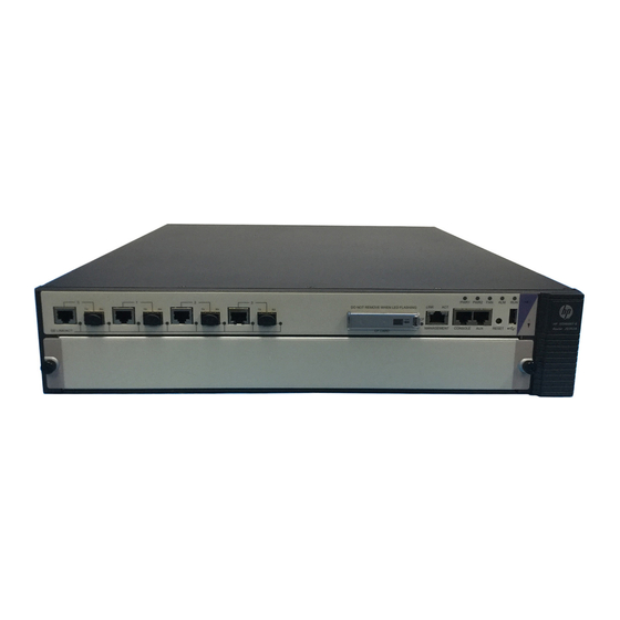
- Page 79 Appendix A Chassis views and Technical specifications Chassis views Figure 65 HSR6602-G/HSR6602-G TAA front view (1) 1000 Mbps Ethernet port (2) CF card slot (CF CARD) (3) CF card LED (4) Status LED (5) USB port (6) Reset button (RESET) (7) Auxiliary port (AUX) (8) Console port (CONSOLE) (9) Management Ethernet port (MANAGEMENT)
- Page 80 Figure 66 HSR6602-XG/HSR6602-XG TAA front view (1) 1000 Mbps Ethernet port (2) 10 Gbps Ethernet port (3) CF card slot (CF CARD) (4) CF card LED (5) Status LED (6) USB port (7) Reset button (RESET) (8) Auxiliary port (AUX) (9) Console port (CONSOLE) (10) Management Ethernet port (MANAGEMENT) (11) FIP slot (slot 1)
- Page 81 Power module Each HP HSR6600 router provides two power module slots, PWR1 and PWR2 on its rear panel, and is shipped with a filler panel on PWR2. You can install one or two power modules for the router as needed.
- Page 82 Figure 68 AC power module appearance (1) AC-input power receptacle (2) Power input status LED (3) Power output status LED (4) Handle (5) Power switch Table 26 AC power module specifications Item Specification Model PSR300-12A Rated voltage range 100 VAC to 240 VAC; 50 Hz or 60 Hz Maximum input current Maximum power 300 W...
- Page 83 10 A Maximum power 300 W Fan tray Each HP HSR6600 router provides a fan tray slot on its rear panel. You can install a fan tray for heat dissipation. NOTE: The fan tray is supplied with the router. Figure 70 Fan tray...
- Page 84 Port specifications Ports and slots Table 29 Port and slot specifications Item Description Console port AUX port USB port • HSR6602-G/HSR6602-G TAA—Four GE combo interfaces Ethernet port • HSR6602-XG/HSR6602-XG TAA—Four combo interfaces and two 10 GE ports CF card slot Interface module slot 1, supports FIP-10/20 Console port...
- Page 85 Management Ethernet port The management Ethernet port is a 10Base-T/100Base-TX/1000Base-T RJ-45 port. It allows you to upgrade software and manage the router through a network management server without using any service interface of the router. The management Ethernet port is used only for managing the router and it has no service processing capabilities such as data forwarding.
- Page 86 Fiber Ethernet port Table 34 Fiber Ethernet port specifications Item Specification Connector type Transceiver module type Interface standards 802.3, 802.3u, and 802.3ab Short-haul Mid-haul Super long Long haul Long haul Type multi-mode single mode haul (1550 (1310 nm) (1550 nm) (850 nm) (1310 nm) Transmission...
- Page 87 Central Connector Max. transmission Model Fiber type wavelength type distance SFP-XG-LH40-SM155 1550 nm 9/125μm single mode 40 km (24.86 miles) Flexible interface platform modules The HSR6600 Router Series supports flexible interface platform (FIP) modules FIP- 1 0 and FIP-20. You can install High-speed Interface Modules (HIMs) and Multifunctional Interface Modules (MIMs) on a FIP to support different network services as needed.
- Page 88 Table 38 FIP-10 specifications Item Specification Not supported 4 MIMs supported at the same time Hot-swapping Supported Slot Four FIP-20 You can plug up to two HIMs or two MIMs into the FIP-20. The FIP-20 also supports intermix of a HIM and a MIM.
- Page 89 Ethernet, POS, and E1. NOTE: No interface modules are supplied with the router. Purchase them yourself. • An interface module must be installed on a FIP. • HP 6600/HSR6600/HSR6800 Router Series For information about interface module specifications, see • Interface Module Guide...
- Page 90 The system is accessing the CF card. In this state, do (yellow/green) Flashing green not remove the CF card. Steady yellow It is a non HP CF card. The power module is not in position. Steady green The power module is supplying power properly. PWR1...
- Page 91 Status Description The system is operating properly and there is no alarm. (red) A fault has occurred. In this state, check the system log Steady red immediately. The system is powered off or the router is faulty. Flashing at 1 Hz The router operates properly as configured.
- Page 92 The system is accessing the CF card. In this state, do (yellow/green) Flashing green not remove the CF card. Steady yellow It is a non HP CF card. The power module is not in position. Steady green The power module is supplying power properly. PWR1...
- Page 93 Status Description No link is present. Steady green A 1000 Mbps link is present. SFP0 through Flashing green Data is being received or transmitted at 1000 Mbps. SFP3 (yellow/green) Steady yellow A 100 Mbps link is present. Flashing yellow Data is being received or transmitted at 100 Mbps. No link is present.
- Page 94 HIM/MIM LEDs For description of HIM/MIM LEDs, see HP A6600 Router Series Interface Module Guide. Power module LEDs Figure 77 AC power module LED Table 44 AC power module LED description Status Description No power is input or the power module has an input problem.
- Page 95 Appendix C Cable management When an HSR6600 router is mounted in a 19-inch standard rack, the interface cables are routed through the cable management brackets, bound at cabling racks on chassis sides, and then routed up or down, depending on the available equipment room condition. The power cables run along the two sides of the chassis and out of the chassis either from the chassis top or the raised floor depending on the equipment room conditions (power distribution cabinet, lightning protection box, and connector strip, etc.) of the exchange office.
- Page 96 Cable management guidelines When you route and bundle up cables, follow these guidelines: • Bind and route the cables neatly inside the rack, and make sure that the cables are not kinked or bent. Figure 79 Correct and incorrect cable binding The cable bend radius at connectors must be at least 5 times the cable diameter, and must be at •...
- Page 97 Figure 80 Cutting the cable ties When you bend cables, bind cables as shown in Figure 81. To avoid cable core break due to • excessive stress, do not tie up the cables in the bending area. Figure 81 Binding the cables Route, bind, and attach excess cables for easy, safe maintenance activities and proper operations.
- Page 98 Figure 82 Securely fasten cables (1) (1)(2) (1) (1)(2) (1) Flat washer (2) Spring washer (3) Nut Fasten heavy or rigid power cables at the connectors to relief stress. • Do not use tapping screws to fasten the connecting terminals. •...
- Page 99 Figure 83 Routing cables...
- Page 100 Appendix D Arranging slots and numbering interfaces Slot arrangement The router provides many types of interfaces, such as console, AUX, GigabitEthernet, serial (synchronous) and E1 ports. This chapter describes how these interfaces are numbered. Figure 84 Slot arrangement on the SR6602-X1 Figure 85 Slot arrangement on the SR6602-X2 NOTE: The numbers in...
- Page 101 Numbering interfaces Before installing a HIM/MIM, you must install a FIP. A FIP20 supports both HIMs and MIMs, while a FIP- 1 0 supports only MIMs. The interfaces of the router are numbered in the form of interface-type X/Y/Z, Where, interface-type: Type of the interface such as GE port and serial port.
- Page 102 GigabitEthernet 1/2/2 • • GigabitEthernet 1/2/3...
- Page 103 Related information Documents To find related documents, browse to the Manuals page of the HP Business Support Center website: http://www.hp.com/support/manuals For related documentation, navigate to the Networking section, and select a networking category. •...
- Page 104 Conventions This section describes the conventions used in this documentation set. Command conventions Convention Description Boldface Bold text represents commands and keywords that you enter literally as shown. Italic Italic text represents arguments that you replace with actual values. Square brackets enclose syntax choices (keywords or arguments) that are optional. Braces enclose a set of required syntax choices separated by vertical bars, from which { x | y | ...
- Page 105 Network topology icons Represents a generic network device, such as a router, switch, or firewall. Represents a routing-capable device, such as a router or Layer 3 switch. Represents a generic switch, such as a Layer 2 or Layer 3 switch, or a router that supports Layer 2 forwarding and other Layer 2 features.
- Page 106 Interface module, cable, and connection failure,70 Connecting the AUX cable,18 Interface modules,83 Connecting the power cord,16 Contacting HP,97 Conventions,98 Labeling cables,89 Cooling system failure,69 Logging in through the console port,33 Logging in to the router through Telnet/SSH,38 Logging in to the router through the AUX...
- Page 107 Replacing a CF card,43 Safety recommendations,1 Replacing a fan tray,45 Saving the current configuration of the router,58 Replacing a FIP module,42 Slot arrangement,94 Replacing a HIM/MIM,42 Slot arrangement for FIPs,94 Replacing a memory module,46 Software upgrade failures,70 Replacing a power module,41 Solving system faults,57...