Advertisement
Quick Links
Dual-block Multi-function Gas Control Valves
Introduction
x Application
x Electrical Ratings
x Specifications
Installation
x Mounting
x Standard Wiring (From Burner Sequence Control)
x 4-Pin Connector Plug Wiring (From Burner Sequence Control)
x GM-4_6_ Connection of Impulse Lines
x Checkout Procedure
Adjustments
x GM-_ _1_ (Dual On/Off Fast Open with Flow Adjustment)
x GM-_ _2_ (Dual On/Off Step-slow Opening with Flow Adjustment)
x GM-_ _3_ (Dual On/Off with Pressure Regulator)
x GM-_ _4_ (Dual On/Off with Step-slow Opening with Pressure Regulator)
x GM-4_5_ (Dual On/Off with Servo Precision Regulator)
x GM-4_6_ (Dual On/Off with Gas/Air Ratio Control)
Repairs and Replacement
© 1998 Johnson Controls, Inc.
Part No. 24-8711-48, Rev. A
Code No. LIT-121892
Gas Combustion Combination Controls and Systems Section G
GM-20/25 and GM-40/45 Series
Installation Sheets Manual 121
Technical Bulletin GM-20/25
Issue Date 1298
Page
www.johnsoncontrols.com
GM-40/45
3
3
3
4
5
5
6
8
9
10
11
11
12
12
13
13
15
19
1
Advertisement

Related Manuals for Johnson Controls GM 20 Series


Summary of Contents for Johnson Controls GM 20 Series
- Page 1 GM-_ _4_ (Dual On/Off with Step-slow Opening with Pressure Regulator) x GM-4_5_ (Dual On/Off with Servo Precision Regulator) x GM-4_6_ (Dual On/Off with Gas/Air Ratio Control) Repairs and Replacement © 1998 Johnson Controls, Inc. Part No. 24-8711-48, Rev. A www.johnsoncontrols.com Code No. LIT-121892...
- Page 2 2 G—GM-20/25 and GM-40/45 Series Dual-block Multi-function Gas Control Valves Technical Bulletin...
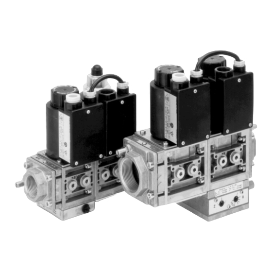
- Page 3 Introduction Figure 1: GM Series Dual-block Multi-function Gas Control Valves The GM Series dual-block multi-function gas control valves are intended Application for use on atmospheric and forced-draft gas burners in heating installations. This multi-functional control on a dual-block valve body provides a compact answer to gas train applications.
-
Page 4: Specifications
The performance specifications are nominal and conform to acceptable industry standards. For application at conditions beyond these specifications, consult the local Johnson Controls office. Johnson Controls, Inc. shall not be liable for damage resulting from misapplication or misuse of its products. -
Page 5: Installation
IMPORTANT: This technical bulletin is intended as a guide for authorized service personnel installing or servicing Johnson Controls products. Carefully follow all instructions in this sheet and all instructions on the appliance. Limit repairs, adjustments, and servicing to the operations listed in this sheet or on the appliance. -
Page 6: Standard Wiring
The GM Series valve may be mounted on a horizontal manifold with the solenoid actuator pointed up (vertical) or in any position not exceeding 90 from the vertical. The valve may also be mounted on a vertical manifold in any position around its axis (see Figure 2). Do not install the solenoid actuator upside down. - Page 7 Note: Figure 3 shows wiring connections for individual valve opening. For simultaneous valve opening, wire a jumper between Terminals V1 and V2 of either the electrical box on the first or second valve. 5. Use a wrench to tighten the PG 13.5 cable compression plug to secure wires and prevent moisture from entering the terminal box.
- Page 8 4-Pin Connector WARNING: Shock hazard. Avoid electrical shock and equipment Plug Wiring damage by disconnecting electrical power to the valve (From Burner before proceeding. Sequence Control) CAUTION: Equipment damage hazard. To prevent possible grounding of the 24 VAC transformer secondary, do not connect the ground wire on 24 VAC models.
- Page 9 The internal diameter of the impulse tubes for the combustion air (P ) and GM-4_6_ the combustion chamber pressure (P ) should be 4.0 mm (5/32 in.), see Connection of Figure 5. Make the connections as short as possible and route to prevent Impulse Lines the entry of condensate into the controller.
- Page 10 Checkout WARNING: Fire or explosion hazard. Verify that the valve Procedure functions properly and there are no gas leaks. Follow this checkout procedure before leaving the installation. Failure to verify proper valve installation, equipment operation, and gas tight connections may result in fire, explosion, property damage, and injuries or death.
- Page 11 Adjustments IMPORTANT: All adjustments must be made in conjunction with the gas appliance and in accordance with the appliance manufacturer’s instructions. Only authorized personnel should make adjustments. See each valve model version for specific adjustments. WARNING: Explosion hazard. The minimum flow rate of the valve must not be adjusted below the minimum safe working rate of the appliance.
- Page 12 This valve provides adjustable step/slow opening for smooth ignition in a GM-_ _2_ burner application. The valve is factory set to maximum start gas position (Dual On/Off and maximum flow position. Adjust the hydraulic damper at the top of the Step-slow solenoid coil to set the desired flow rate through the valve as well as the Opening...
- Page 13 This valve provides controls for step/slow opening (for smooth ignition) GM-_ _4_ and pressure regulation (for maintaining outlet gas pressure). (Dual On/Off Step-slow Refer to the GM-_ _3_ version for setting the gas pressure at the valve Opening with outlet. For setting of the start gas position and maximum flow rate, see the Pressure GM-_ _2_ version.
- Page 14 The start gas pressure (P ) remains at the set level until the pressure tap plug is replaced and tightened. The pressure then rises to the setpoint (P IMPORTANT: P must be greater then P in order for the valve to operate properly.
- Page 15 This valve provides mechanical modulating control of the gas outlet GM-4_6_ pressure at a consistent ratio to the main air blower pressure. An example (Dual On/Off of a typical installation is shown in Figure 12. The burner control responds with Gas/Air to a higher demand for heat by increasing the amount of air being supplied Ratio Control) to the burner, resulting in an increased air pressure.
- Page 16 To adjust the valve, first check the factory settings. The adjustments for the gas/air ratio (R scale) and zero set (Z scale) are located on both sides of the gas/air ratio control module (see Figure 13). The factory settings are: x Gas/air ratio (R): 1:2 x Zero set (Z): Figure 13: Zero Set and Gas/Air Ratio Adjustments...
- Page 17 0.7:1 0.6:1 (in. W.C.) (in. W.C.) (in. W.C.) (in. W.C.) Figure 14: Analyses Chart Zero Set (Z) With the correct gas/air ratio (R) set, there may be some minor deviations Adjustment (caused by friction, etc.) at very low pressures. To allow for fine adjustment of the valve, the zero set can be changed.
- Page 18 18 G—GM-20/25 and GM-40/45 Series Dual-block Multi-function Gas Control Valves Technical Bulletin...
-
Page 19: Repairs And Replacement
Repairs and Replacement Field repairs must not be made, except to replace the filter or strainer. For a replacement part, contact the nearest Johnson Controls representative or the original equipment manufacturer. CAUTION: Label all wires prior to disconnection when servicing valves. - Page 20 8. Paint the pipe connections and flanges of the valve with a rich soap and water solution. If bubbles occur, this is an indication of a leak. To stop a leak, tighten joints and pipe connections. Replace the part if the leak cannot be stopped.