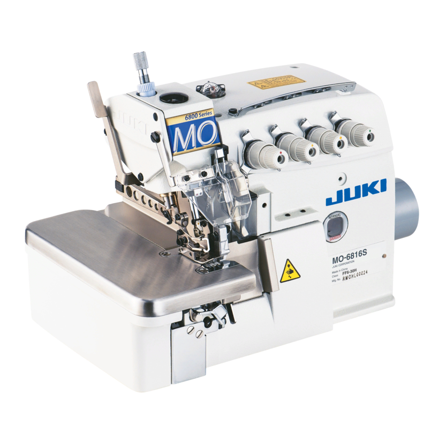
JUKI MO-6800S Series Instruction Manual
Hide thumbs
Also See for MO-6800S Series:
- Engineer's manual (72 pages) ,
- Instruction manual (33 pages)
Table of Contents
Advertisement
Advertisement
Table of Contents

Related Manuals for JUKI MO-6800S Series


Summary of Contents for JUKI MO-6800S Series
- Page 1 MO-6800S(D)/DD10 Series INSTRUCTION MANUAL...
-
Page 2: Table Of Contents
CONTENTS 1. SPECIFICATION ......................1 1-1. Specifications of the sewing machine head .................. 1 1-2. Specifications of the control box ....................1 2. NAMES OF MAJOR PARTS .................... 2 3. INSTALLATION ........................ 3 3-1. Installing the table and the table stand ..................3 3-2. -
Page 3: Specification
DC × 27 (Standard) Motor DD motor Presser foot lift 5 to 7 mm Lubricating oil JUKI MACHINE OIL #18 Exclusive grease Part number: 23640204 (100 g tube) Grease Part number: 40006323 (10 g tube) Weight 28 kg - Equivalent continuous emission sound pressure level (L ) at the workstation: A-weighted value of 83.0 dB;... -
Page 4: Names Of Major Parts
2. NAMES OF MAJOR PARTS ❶ Presser foot lifting lever ❷ Presser foot (asm.) ❸ Thread stand ❹ Oil gauge ❺ Pulley ❻ Cloth plate cover ❸ ❺ ❶ ❹ ❷ ❻ – 2 –... -
Page 5: Installation
3. INSTALLATION WARNING : • Machine installation should only be carried out by a qualified technician. • Contact your dealer or a qualified electrician for any electrical work that may need to be done. • The sewing machine weighs 28 kg. The installation should be carried out by two or more people. •... -
Page 6: Installing The Pedal Sensor
2) Assemble the waste disposal set and the thread stand. 3-2. Installing the pedal sensor 1) Ins tal l the pedal sens or to the table wi th mounting screws ❶ supplied with the unit. It is necessary to install the pedal sensor at such a position that the connecting rod is perpendicu- lar to the table. -
Page 7: Attaching The Connecting Rod
3-3. Attaching the connecting rod WARNING : To protect against possible personal injury due to abrupt start of the machine, be sure to start the following work after turning the power off and a lapse of 5 minutes or more. Fix connecting rod ❶... -
Page 8: Connecting The Connector
3-4. Connecting the connector WARNING : • To protect against personal injury resulting from abrupt start of the sewing machine, be sure to turn the power OFF, unplug the machine and wait for five minutes or more before installing the pedal sensor. -
Page 9: How To Install The Power Plug
3-5. How to install the power plug WARNING : 1. Be sure to attach the ground wire (green/yellow) to the specified location (on the ground side). 2. Take care not to allow terminals to come in contact with each other. 1) Connect the power cord to power plug ❶... -
Page 10: Lubrication And Drainage
1) Remove oil sight window ❶ from the oil inlet. Add lubricating oil specifically made for machines which run at a super-high speed (JUKI MACHINE OIL #18) supplied with the unit or equivalent through the oil inlet. When the oil surface reaches the space between two marker lines on the oil gauge, tighten oil sight window ❶ . - Page 11 3) To extend the usage term, this machine has equipped an oil filter ❷ . Clean up this oil filter ❷ once every month and change it with a new one where necessary. ❷ Needle cooling lubrication oil : SILICON OIL SILICON OIL SILICON OIL –...
-
Page 12: Exclusive Grease Replenishment (Only For The Mo-6800S)
❷ 1) Remove grease replenishing rubber plug ❶ from 2) Replenish grease by means of a tip of screw- driver ❸ , ❷ or the like. Use JUKI GREASE A for the needle bar compartment. the replenishment of grease JUKI GREASE A: 40006323 (part number) 2. -
Page 13: Preparation Before Sewing
5. PREPARATION BEFORE SEWING 5-1. Threading WARNING : Follow the procedures for threading. Wrong threading can cause stitching troubles such as thread breakage, stitch skipping and puckering. MO-6804 MO-6814 – 11 –... - Page 14 MO-6814- △△△ -44H MO-6816 – 12 –...
- Page 15 MO-6816- △△△ -50H MO-6816- △△△ -60H – 13 –...
-
Page 16: Adjusting The Thread Tension
5-2. Adjusting the thread tension The thread tension should be adjusted properly according to the kinds and the thickness of the materials, stitch length, and seam width, etc. In addition, adjust the nuts case by case individually. Turn the nuts clock- wisely will increase the thread tension. -
Page 17: Replace The Needle
(3) Adjusting the looper thread cam thread guide 1) In the case the looper thread is not appropriately adjusted, thread loops cannot be formed with consistency. ⊖ (Thread can be excessively loos- ⊕ ened or thread loops cannot be formed.) ⊖... -
Page 18: Adjusting The Stitch Length
5-4. Adjusting the stitch length WARNING : To protect against possible personal injury due to abrupt start of the machine, be sure to start the following work after turning the power off and ascertaining that the motor is at rest. Change the stitch length appropriately according to the material to be used, differential feed ratio or other rel- evant factors. -
Page 19: Replace The Knives
5-6. Replace the knives WARNING : To protect against possible personal injury due to abrupt start of the machine, be sure to start the following work after turning the power off and ascertaining that the motor is at rest. ❸ ❹... -
Page 20: Adjusting The Overedge Width
5-7. Adjusting the overedge width WARNING : To protect against possible personal injury due to abrupt start of the machine, be sure to start the following work after turning the power off and ascertaining that the motor is at rest. 1) Turn the pulley to move the upper knife ❹... -
Page 21: Adjusting The Presser Foot
5-9. Adjusting the presser foot (1) Adjusting the presser foot position Increase ❶ Decrease ❷ ❼ ❼ ❹ ❻ ❺ ❸ * This figure gives an illustration of the MO-6814S 1) Loosen adjusting screw ❶ and screw ❼ of the presser foot. 2) Move the presser foot ❻... - Page 22 (2) Adjusting the lift amount of the presser foot ❷ 1 mm ❶ ❸ ❻ ❺ ❹ * This figure gives an illustration of the MO-6814S 1) Turn the pulley to lower the feed dog until the bottom of the presser horizontally comes in contact with the throat plate.
-
Page 23: Adjusting The Feed Dog
5-10. Adjusting the feed dog WARNING : To protect against possible personal injury due to abrupt start of the machine, be sure to start the following work after turning the power off and ascertaining that the motor is at rest. (1) Adjusting the feed dog height ❷... -
Page 24: The Relationship Between The Needle And The Looper
5-11. The relationship between the needle and the looper WARNING : To protect against possible personal injury due to abrupt start of the machine, be sure to start the following work after turning the power off and ascertaining that the motor is at rest. (1) The relationship between the needle and the upper looper When the upper looper moves to the leftmost point, the distance... - Page 25 (3) The relationship between the upper looper and the lower looper When the upper and the lower loopers cross, keep them as close as possible. Somehow, the loopers shall not either touch nor col- lide to each other. The clearance of 0.05 to 0.2 mm should be provided between the upper and lower loopers when they are crossing.
-
Page 26: Adjusting The Amount Of Travel Of The Double Chainstitch Looper
5-12. Adjusting the amount of travel of the double chainstitch looper WARNING : To protect against possible personal injury due to abrupt start of the machine, be sure to start the following work after turning the power off and ascertaining that the motor is at rest. The double chainstitch looper makes elliptic move- ment. -
Page 27: Operation Procedure
6. OPERATION PROCEDURE 6-1. Operation panel ❺ ❸ ❻ ❹ ❷ ❶ How to press Function the button Short time This button is used for changing over the current mode to the function setting ❶ mode. This button is used for confirming the settings you have changed. Short time ❷... -
Page 28: Font Comparison Table
6-2. Font comparison table Arabian figures: Actual shape of figure Display Arabian figures: Actual shape of figure Display Actual shape of figure Display – 26 –... -
Page 29: Function Setting
6-3. Function setting Functions can be selected and set as described below. ❶ . 1) Press The display on the display section A is changed over to display the Function setting No. (P- * *). (The display item that has been previously changed is displayed unless you have turned the power OFF after you changed the setting last time. -
Page 30: Function Setting Table
6-4. Function setting table Item Description Range Initial value Maximum sewing speed The maximum sewing speed is limited with the function 200-P41 setting number P41. Extra- Gen- High (It can be set under the Service Level mode.) high eral lift Refer to "■... - Page 31 Item Description Range Initial value Intermittent suction non-op- In the case "5" is selected for "P17", the suction 1 is 0-9000 eration time for pedal con- held in the stopped state for the period of time set for trol suction 1 this function setting number "P21"...
- Page 32 Item Description Range Initial value N u m b e r o f s t i t c h e s f o r In the case "6" is selected for "P17", the suction 1 is 0-200 keeping the intermittent kept in the operating state for the number of stitches set suction in the operating for this function setting number "P31"...
- Page 33 ■ Model selection table Maximum number of Model selection Maximum sewing speed Model name revolutions setting (P54) (P01) initial value (P41) MO-6804S-0E4-30H General 7000 6500 MO-6804S-0A4-150 General 7000 6500 MO-6814S-BE6-40H High lift 6500 6000 M O -6814S - B E6-24H / General 7000 6500...
-
Page 34: Details Of Setting Of The Main Functions
6-5. Details of setting of the main functions ❸ ❺ ❹ ❷ ❶ ① Stop position setting (Function setting No. P02) This function setting number is used for setting the stop position of the needle. 0: The needle stops at its upper position 1: The needle stops at its lower position 2: The needle stop position is not specified The needle stop position can also be changed with the relevant button on the operation panel. - Page 35 ③ Selection of the presser foot lifting function (Function setting No. P16) This is the function to select whether the presser foot is lifted or not when the back part of the pedal is depressed. * This selection is enabled in the case the presser foot lifting device is connected to the sewing machine. (Refer to the Engineer's Manual for the detailed connection method.) 0: The presser foot lifting operation is not carried out.
-
Page 36: Initialization Of The Function Setting Data
6-6. Initialization of the function setting data The function setting data you have changed arbitrarily can be stored in memory. If you change the data after- ward, it can be returned to the aforementioned data that you have stored in memory. 1) The initialization screen is displayed by keeping ❸... -
Page 37: Hand Led Light
6-7. Hand LED light Brightness of hand LED light ❶ can be changed by ❻ ❻ pressing . When you keep held pressed for a long time, the light adjustment function ❻ is changed over to the color temperature changing function. -
Page 38: About The Usb
6-8. About the USB WARNING : The device to be connected to the USB port should have the rated current value or less as shown below. If any device rated current value of which is higher than the rated current value, the main body of the sewing machine or the USB device connected can be damaged or malfunction. -
Page 39: Maintenance
7. MAINTENANCE WARNING : 1. Turn off the power switch before carrying out cleaning. The machine may operate if the treadle is pressed incautiously, which could result in injury. 2. Be sure to wear protective goggles and gloves when handling the lubricating oil and grease so that they do not get into your eyes or onto your skin, otherwise inflammation can be resulted. -
Page 40: Adjustment Dimension Values
8. ADJUSTMENT DIMENSION VALUES 8-1. Dimensions use to adjusting the looper and the needle guard WARNING : 1. To avoid possible accidents due to unfamiliarity with the machine, get a maintenance man who has a good knowledge of the machine or serviceman of our distributor to adjust the machine or replace any of its parts. -
Page 41: Dimensions Related To The Position Of The Thread Take-Up And The Looper Thread Cam (Standard Adjustment)
8-2. Dimensions related to the position of the thread take-up and the looper thread cam (standard adjustment) WARNING : To protect against possible personal injury due to abrupt start of the machine, be sure to start the following work after turning the power off and ascertaining that the motor is at rest. (1) Position of the needle thread take-up and the needle thread guide MO-6804 MO-6814**... - Page 42 (2) Position of the looper thread take-up and the looper thread guide (Unit : mm) Model MO-6804 11.5 17.5 28.5 MO-6814-2 △ H 21.5 14.5 MO-6814-3 △ H 21.5 14.5 MO-6814-4 △ H 21.5 14.5 28.5 MO-6814-30P 11.5 17.5 28.5 MO-6816-3 △...
-
Page 43: Error Code List
9. ERROR CODE LIST Error code Description Overvoltage error This error code is displayed when the alternating-current voltage exceeds 317 V - 325 V. Low voltage error This error code is displayed when the alternating-current voltage drops below 170 V. Communication fault between the operation panel and the electrical Pedal signal fault Lock error... - Page 44 10. TABLE DRAWING Unit:mm Difference:±2 1200 断面 断面 – 42 –...
- Page 45 Fully-sunken type table * Auxiliary table is required. Unit : mm Difference : ±2 Weight :12.4 kg ±5% 1200 1020 9- R20 4 - R10 23 0 ø19.5 断面 A = This part has to be removed when installing the auto hemmer device to the sewing machine.
- Page 46 Auxiliary table for fully-sunken type table Unit : mm Difference : ±2 Weight :4.25 kg ±5% – 44 –...
- Page 47 Fully-sunken type table (bracket type) 1200 1020 3-R20 3-R10 4-R10 ø19.5 Through hole A = This part has to be removed when installing the auto hemmer device to the sewing machine. – 45 –...