Table of Contents
Advertisement
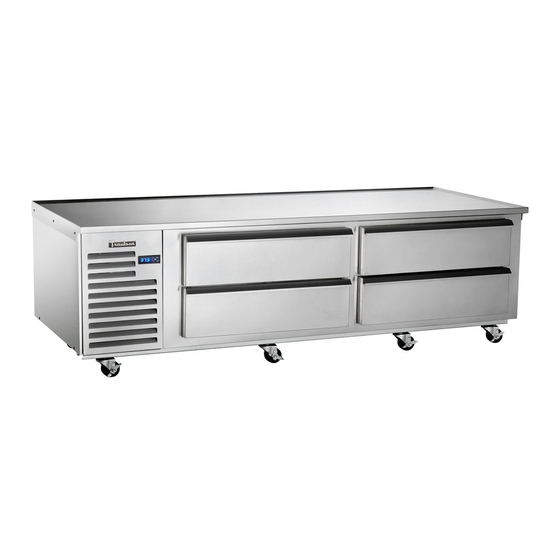
Traulsen Refrigeration
SERVICE MANUAL #07
Instructions For The Troubleshooting
And Repair Of All Traulsen TE-Series
Refrigerated Equipment Stand Models
-NOTICE-
This Manual is prepared for the use of trained Authorized Traulsen Service Agents and should not be used
by those not properly qualified. This manual is not intended to be all encompassing, but is written to
supplement the formal training, on-the-job experience and other product knowledge acquired by Autho-
rized Traulsen Service Agents. Before proceeding with any work, you should read, in its entirety, the repair
procedure you wish to perform to determine if you have the necessary tools, instruments and skills required
to perform the procedure. Procedures for which you do not have the necessary tools, instruments and
skills should be performed only by a trained Authorized Traulsen Service Agent.
Reproduction or other use of this Manual, without the express written consent of Traulsen, is prohibited.
FORM NUMBER TR35896 - REVISED. 4/08
Advertisement
Table of Contents

Related Manuals for Traulsen TE Series


Summary of Contents for Traulsen TE Series
- Page 1 Refrigerated Equipment Stand Models -NOTICE- This Manual is prepared for the use of trained Authorized Traulsen Service Agents and should not be used by those not properly qualified. This manual is not intended to be all encompassing, but is written to supplement the formal training, on-the-job experience and other product knowledge acquired by Autho- rized Traulsen Service Agents.
-
Page 2: Table Of Contents
The serial tag is a permanently affixed sticker on FORT WORTH, TX. which is recorded vital electrical and refrigeration data about your Traulsen product, as well as the model SERIAL MODEL and serial number. This tag is located on the upper VOLTS right interior wall of all TE-Series models. -
Page 3: General Information
To assure optimum performance, the condensing unit stiff brush or wisk broom. For more information please of your Traulsen unit MUST have an adequate supply refer to “Section V.a” of the TE-Series Owner’s of air for cooling purposes. Therefore, the operating Manual. -
Page 4: Control Locations
II. GENERAL INFORMATION (cont’d) II. j - CONTROL LOCATION: II. l - SPECIFICATIONS: On all TE-Series refrigerator models, the micro- TE-Series Refrigerated Equipment Stands processor control is located on the louver assembly. TE036 TE048 TE060 The louvers/refrigeration system are mounted standard on the left side, but as an option are available mounted Horsepower 1/3 HP... -
Page 5: Removal & Replacement Of Parts A
III. REMOVAL & REPLACEMENT OF BASIC PARTS WARNING: DISCONNECT THE ELECTRICAL POWER TO THE MACHINE AND FOLLOW LOCKOUT/TAGOUT PROCEDURES. III. a - LOUVER ASSEMBLY/SYSTEM ACCESS: III. b - EVAPORATOR HOUSING COVER: Remove the back cover by removing the four screws To remove the louver assembly first place your hands under the louver panel and lift this up off the bracket which secure this to the cabinet (see figure 6). -
Page 6: Drawer Gaskets
III. REMOVAL & REPLACEMENT OF BASIC PARTS (cont’d) WARNING: DISCONNECT THE ELECTRICAL POWER TO THE MACHINE AND FOLLOW LOCKOUT/TAGOUT PROCEDURES. III. e - DRAWER GASKETS: III. h - ACCESSING START COMPONENTS (cont’d): To remove the gasket to be replaced, grasp it firmly by one corner and pull it out. -
Page 7: Condenser Fan Motor And/Or Blade
IV. a - REPLACING THE CONDENSER FAN MOTOR AND/OR BLADE STEP 1: Remove the louver assembly as outlined in WARNINGS: section “III. a” to gain access through left side. 1) DISCONNECT THE ELECTRICAL POWER TO THE MACHINE AND FOLLOW LOCKOUT/TAGOUT STEP 2: Remove the screws holding the fan motor PROCEDURES. -
Page 8: Condenser Coil
IV. b - REPLACING THE CONDENSER COIL STEP 1: Remove the louver assembly as outlined in WARNINGS: section “III. a”. 1) DISCONNECT THE ELECTRICAL POWER TO THE MACHINE AND FOLLOW LOCKOUT/TAGOUT STEP 2: Recover the refrigerant in the system PROCEDURES. following the current EPA Guidelines for refrigerant recovery. -
Page 9: Evaporator Fan
IV. c - REPLACING THE EVAPORATOR FAN STEP 1: Begin by removing the back cover by first WARNINGS: removing the four screws which secure this to 1) DISCONNECT THE ELECTRICAL POWER TO THE the cabinet (see illustration 1). MACHINE AND FOLLOW LOCKOUT/TAGOUT PROCEDURES. -
Page 10: Evaporator Coil
IV. d - REPLACING THE EVAPORATOR COIL WARNINGS: STEP 1: Remove evaporator housing cover as outlined in section “III. b”. 1) DISCONNECT THE ELECTRICAL POWER TO THE MACHINE AND FOLLOW LOCKOUT/TAGOUT STEP 2: Recover the refrigerant in the system PROCEDURES. following the current EPA Guidelines for refrigerant recovery. -
Page 11: Compressor
IV. e - REPLACING THE COMPRESSOR NOTE: Compressor models will vary with each cabinet WARNINGS: model, but the basic removal instructions can be followed. 1) DISCONNECT THE ELECTRICAL POWER TO THE MACHINE AND FOLLOW LOCKOUT/TAGOUT STEP 1: Recover the refrigerant in the system PROCEDURES. -
Page 12: Wiring Diagrams
V. WIRING DIAGRAM -11-... -
Page 13: Service Procedures & Adjustments
VI. SERVICE PROCEDURES & ADJUSTMENTS WARNING: CERTAIN PROCEDURES IN THIS SECTION REQUIRE ELECTRICAL TEST OR MEASUREMENTS WHILE POWER IS APPLIED TO THE MACHINE. EXERCISE EXTREME CAUTION AT ALL TIMES. IF TEST POINTS ARE NOT EASILY ACCESSIBLE, DISCONNECT POWER, ATTACH TEST EQUIPMENT AND REAPPLY POWER TO TEST. VI. -
Page 14: Evacuating System
VI. SERVICE PROCEDURES & ADJUSTMENTS (cont’d) WARNING: CERTAIN PROCEDURES IN THIS SECTION REQUIRE ELECTRICAL TEST OR MEASUREMENTS WHILE POWER IS APPLIED TO THE MACHINE. EXERCISE EXTREME CAUTION AT ALL TIMES. IF TEST POINTS ARE NOT EASILY ACCESSIBLE, DISCONNECT POWER, ATTACH TEST EQUIPMENT AND REAPPLY POWER TO TEST. VI. -
Page 15: System Clean-Up
VI. SERVICE PROCEDURES & ADJUSTMENTS (cont’d) WARNING: CERTAIN PROCEDURES IN THIS SECTION REQUIRE ELECTRICAL TEST OR MEASUREMENTS WHILE POWER IS APPLIED TO THE MACHINE. EXERCISE EXTREME CAUTION AT ALL TIMES. IF TEST POINTS ARE NOT EASILY ACCESSIBLE, DISCONNECT POWER, ATTACH TEST EQUIPMENT AND REAPPLY POWER TO TEST. VI. -
Page 16: Component Function
VII. ELECTRICAL OPERATION VII. c - COMPONENT FUNCTION: Compressor: Pumps refrigerant thru refrigeration system components and compresses the low pressure vapor into high pressure vapor. Condenser Fan: Draws air across condenser coil to aid in removing heat from the refrigerant and moves air across compressor to aid in cooling the compressor. -
Page 17: Replacement Parts Listing
VIII. REPLACEMENT PARTS LISTING NOTE: Part numbers listed are for standard products as currently manufactured. For products manufactured as other than standard, or for older production units, please contact the factory. PART NO. NAME OF PART PART NO. NAME OF PART CABINET SUPPORTS COMPRESSORS SER-60536-00... -
Page 18: Troubleshooting
IX. TROUBLESHOOTING WARNING: CERTAIN PROCEDURES IN THIS SECTION REQUIRE ELECTRICAL AND REFRIGERA- TION SYSTEM TEST OR MEASUREMENTS WHILE POWER IS APPLIED TO THE MACHINE. EXER- CISE EXTREME CAUTION AT ALL TIMES. IF TEST POINTS ARE NOT EASILY ACCESSIBLE, DISCON- NECT POWER, ATTACH TEST EQUIPMENT AND REAPPLY POWER TO TEST. Compressor will not run, compressor has no current draw. - Page 19 -18-...
- Page 20 For More Information On The Proper Installation, Use and Maintenance Of Traulsen Refrigerated Equipment Stand Models, Please Refer To The Following Materials Available From Your Local Hobart/Traulsen Sales & Service Location: • INTELA-TRAUL Master Service Manual - Form Number TR35705 For Questions Regarding Repair or Warranty Service, Please Contact Traulsen Service At: (800) 825-8220, ext.