Table of Contents
Advertisement
Available languages
Available languages
Quick Links
Advertisement
Chapters
Table of Contents

Related Manuals for PROEL AMP03VR


Summary of Contents for PROEL AMP03VR
- Page 1 MANUALE UTENTE - INSTRUCTION MANUAL Amplificatore PA – PA Amplifier AMP03VR...
-
Page 3: Table Of Contents
INDICE PRECAUZIONI D’USO ..........................4 DESCRIZIONE ............................6 FUNZIONI E CONTROLLI PANNELLO FRONTALE ................ 6 FUNZIONI E CONTROLLI PANNELLO POSTERIORE..............7 MODULO LETTORE REGISTRATORE ....................8 INSTALLAZIONE ........................... 10 ESEMPI DI POSSIBILI CONNESSIONI ..................... 12 CARATTERISTICHE TECNICHE ......................13 CONTENUTO DELLA CONFEZIONE ....................13... -
Page 4: Precauzioni D'uso
PRECAUZIONI D’USO AVVERTENZA:Per ridurre il rischio di folgorazione, non rimuovere il coperchio (o il pannello posteriore). All’interno non sono contenute parti riparabili dall’utente; affidare la riparazione a personale qualificato. ATTENZIONE: Per ridurre il rischio d’incendio o di folgorazione, non esporre questo apparecchio alla pioggia o all’umidità. Questo simbolo, ove compare, segnala la presenza di un voltaggio pericoloso non isolato all’interno del corpo dell’apparecchio –... - Page 5 In caso si verifichino interferenze nel circuito di provenienza, il valore di THD sarà superiore al 10%. Non installare questo apparato in una libreria o in altri luoghi a spazio ristretto PROEL S.P.A. declina ogni responsabilità in caso di scorretta installazione dell’unità. •...
-
Page 6: Descrizione
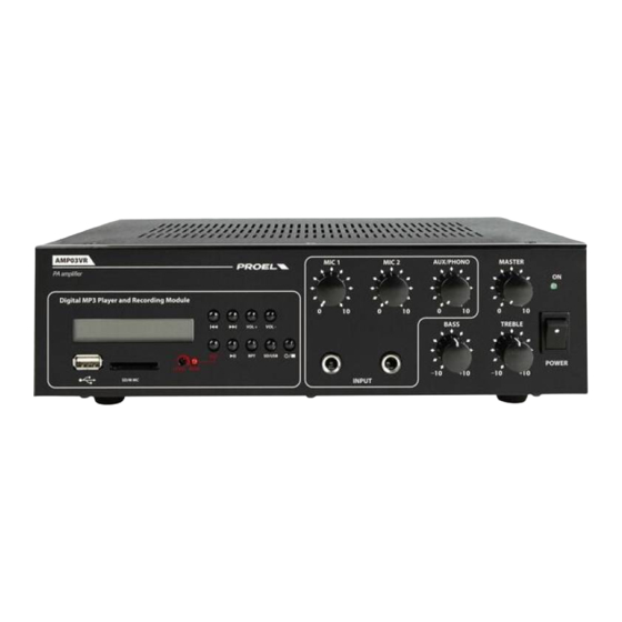
Grazie per aver scelto un prodotto Proel e della fiducia riposta nel nostro marchio, sinonimo di professionalità, accuratezza, elevata qualità ed affidabilità. Tutti i nostri prodotti sono conformi alle normative CE per utilizzazione continua in impianti di diffusione sonora. DESCRIZIONE L’AMP03V è... -
Page 7: Funzioni E Controlli Pannello Posteriore
3. TREBLE Controllo toni Alti 4. BASS Controllo toni Bassi 5. AUX/PHONO Controllo volume ingresso PHONO/AUX posteriore 6. MIC1 – MIC2 Controllo di volume ingressi MIC1 e MIC2 Nota: MIC1 ha la funzione di priorità sugli altri ingressi 7. INGRESSI MIC1 - MIC 2 Jack mono 6.3 mm 8. -
Page 8: Modulo Lettore Registratore
5. SELETTORE Consente di selezionare la sensibilità tra AUX e PHONO 6. INSERT Di serie l’ingresso AMP IN è collegato con l’uscita PRE OUT con un ponticello. E’ possibile ottenere un’ottimizzazione del segnale da amplificare interponendo tra i due terminali un’unità esterna (es. equalizzatore, processore ecc.). - Page 9 5. PEAK Il led s’illumina quando viene raggiunto il livello di picco. Per una buona qualità della registrazione evitare che il led di picco rimanga costantemente acceso 6. REC Dopo aver acceso il modulo (fig.3 rif .9) e regolato opportunamente il livello di registrazione (fig.3 rif .4), questo inciderà...
-
Page 10: Installazione
6. INSTALLAZIONE 1. Connessioni d’ingresso • Gli ingressi MIC1 e MIC2 (fig1, rif.7) sono di tipo Jack Mono 6.3 e sono utilizzabili per il collegamento di microfoni dinamici a bassa impedenza (30-600Ω). L’ingresso MIC1 è provvisto della funzione VOX e, quando viene pilotato con un segnale, provvede a renderlo prioritario escludendo tutti gli altri ingressi;... - Page 11 Linea a tensione costante Per ottenere una linea a tensione costante (25,70,100V) collegare i due terminali rispettivamente al morsetto COM e a quello contrassegnato con il valore di tensione desiderato. − Gli altoparlanti devono essere dotati di un trasformatore avente una tensione d’ingresso uguale a quella fornita dall’amplificatore.
-
Page 12: Esempi Di Possibili Connessioni
ESEMPI DI POSSIBILI CONNESSIONI... -
Page 13: Caratteristiche Tecniche
Cavo di alimentazione di rete Manuale di utilizzo La Proel SpA persegue una politica di costante ricerca e sviluppo, di conseguenza si riserva il diritto di apportare miglioramenti ai prodotti esistenti, senza preavviso e in qualunque momento. REV. 00 41/11... - Page 14 INDICE 2. DESCRIPTION ............................17 3. FRONT PANEL FUNCTIONS AND CONTROLS................17 4. REAR PANEL FUNCTIONS AND CONTROLS ................18 5. PLAYING AND RECORDING MODULE .................... 19 6. INSTALLATION ............................21 7. CONNECTION EXAMPLE ........................23 8. TECHNICAL FEATURE ......................... 24 9.
- Page 15 1. IMPORTANT SAFETY INSTRUCTIONS CAUTION: To reduce the risk of electric shock do not remove cover (or back panel). No user serviceable parts inside. Refer servicing to qualified personnel only. WARNING: To reduce the risk of fire or electric shock, do not expose this apparatus to rain or moisture. This symbol is intended to alert the user of the presence of uninsulated dangerous voltage within the product enclosure that may be of sufficient magnitude to constitute a risk of electric shock to persons.
- Page 16 In case of interference from source signal, THD value will raise over 10%. Don’t place this unit in a bookshelf or in other enclosed spaces. • PROEL S.P.A. is not responsible for any damage that occurs due to a incorrect installation of the unit.
-
Page 17: Description
Thank you for choosing Proel and for your trust in our brand: we strive to guarantee professionalism, accuracy, high quality and reliability to our customers. All of our products comply with EC regulations on sound reinforcement devices. 2. DESCRIPTION AMP03VR was specifically designed to deliver announcements and/or music programs through P.A. systems. -
Page 18: Rear Panel Functions And Controls
4. BASS Low Tone Control 5. AUX/PHONO PHONO/AUX rear input volume control 6. MIC1 – MIC2 Volume Controls of MIC1 & MIC2 inputs Note: MIC1 has priority over all the other inputs 7. MIC1 - MIC 2 INPUT 6,3 mm mono jack 8. -
Page 19: Playing And Recording Module
6. INSERT The AMP IN input is connected with the PRE OUT output by a jumper. The signal requiring amplification can nonetheless be optimized by interposing an external unit (i.e. equalizer, processor, etc.) between the two terminals. Refer to the illustration below for the connection. 7. - Page 20 6. REC After having switched on the module (fig. 3, ref. 9) and set the recording level (fig. 3, ref. 4), connect an audio source to one of the three available inputs (fig. 1, ref. 7 – fig. 2, ref. 4) and adjust its level. Insert the USB key or the SD card in the respective inputs (fig.
-
Page 21: Installation
6. INSTALLATION 1. Input connections • MIC1 and MIC2 inputs (fig. 1, ref. 7) are 6.3 mm mono jacks and can be used to connect low impedance (30- 600 ) dynamic microphones. The MIC1 input features a VOX function that, when driven by a signal, prioritizes it and excludes all other inputs: in this way only the audio signal present on the MIC1 input is reproduced at the output. - Page 22 Constant voltage line In order to get a constant voltage line (25 V, 70 V, 100 V) connect one of the speaker/transformer lines to the COM terminal and the other to the terminal bearing the voltage value that you need. −...
-
Page 23: Connection Example
7. CONNECTION EXAMPLE... -
Page 24: Technical Feature
9. PACKAGE CONTENT Amplifier Power supply cable User manual Proel SpA is committed to a constant research and development policy and therefore reserves the right to change and improve its products at any time without notice . REV. 00 41/11... - Page 26 PROEL S.p.A. (World Headquarters - Factory) Via alla Ruenia 37/43 64027 Sant’Omero (Te) – Italy Tel: +39 0861 81241 Fax: +39 0861 887862 info@proel.com E-mail: www.proel.com...