Table of Contents
Advertisement
Quick Links
Advertisement
Table of Contents

Related Manuals for Panasonic CS-ME5SD3UA


Summary of Contents for Panasonic CS-ME5SD3UA
-
Page 2: Table Of Contents
TABLE OF CONTENTS PAGE PAGE Safety Precautions ..........3 15.1 Indoor Electronic Controller, Blower Fan, Fan Motor & Drain Motor Removal Specifications ............. 5 Procedure...........68 Features ............... 9 Technical Data ..........71 ... -
Page 5: Specifications
2. Specifications Indoor CS-ME5SD3UA Model Outdoor CU-2E18SBU Performance Test Condition AHRI Phase, Hz Single, 60 Power Supply Min. Mid. Max. Min. Mid. Max. 1.32 1.62 2.30 1.32 1.62 2.30 Capacity BTU/h 4400 5500 7800 4400 5500 7800 Running Current Input Power 5.20... - Page 6 Indoor CS-ME5SD3UA Model Outdoor CU-2E18SBU Height (I/D) mm (inch) 200 (7-7/8) Dimension Width (I/D) mm (inch) 750 (29-17/32) Depth (I/D) mm (inch) 640 (25-7/32) Weight Net (I/D) kg (lb) 19 (42) Pipe Diameter Piping mm (inch) 6.35 (1/4) / 9.52 (3/8)
- Page 7 Indoor CS-ME7SD3UA Model Outdoor CU-2E18SBU Performance Test Condition AHRI Phase, Hz Single, 60 Power Supply Min. Mid. Max. Min. Mid. Max. 1.80 2.01 2.90 1.80 2.01 2.90 Capacity BTU/h 6100 6900 9900 6100 6900 9900 Running Current Input Power 5.29 4.02 3.58 5.29...
- Page 8 Indoor CS-ME7SD3UA Model Outdoor CU-2E18SBU Height (I/D) mm (inch) 200 (7-7/8) Dimension Width (I/D) mm (inch) 750 (29-17/32) Depth (I/D) mm (inch) 640 (25-7/32) Weight Net (I/D) kg (lb) 19 (42) Pipe Diameter Piping mm (inch) 6.35 (1/4) / 9.52 (3/8) (Liquid / Gas) Inner Diameter mm (inch)
-
Page 9: Features
3. Features Inverter Technology Wider output power range Energy saving Quick Cooling Quick Heating More precise temperature control Environment Protection Non-ozone depletion substances refrigerant (R410A) Long Installation Piping Long piping up to 25 meter (82 ft) Easy to use remote control ... -
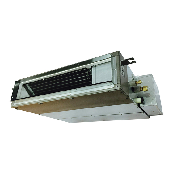
Page 12: Indoor Unit
6. Refrigeration Cycle Diagram Indoor Unit INDOOR LIQUID SIDE 2 WAY VALVE PIPE TEMP. SENSOR 1 INTAKE TEMP. PIPE SENSOR (INLET) TEMP. SENSOR 2 HEAT EXCHANGER (EVAPORATOR) SIDE 3 WAY VALVE COOLING HEATING... -
Page 13: Indoor Unit
7. Block Diagram Indoor Unit Indoor Unit FUSE... -
Page 14: Wiring Connection Diagram
8. Wiring Connection Diagram Indoor Unit ELECTRONIC HAJEM-A CN-CNT CONTROLLER (WHITE) (WHITE) MOTOR CN-FM CN-FSW FLOAT (WHITE) (GREEN) SWITCH RECTIFICATION CIRCUIT DRAIN PUMP INDOOR PIPE TEMPERATURE t˚ SENSOR 2 NOISE FILTER CN-DRMTR1 CN-TH INDOOR PIPE TEMPERATURE (BLUE) CIRCUIT (WHITE) t˚ SENSOR 1 INDOOR AIR TEMPERATURE t˚... -
Page 18: Indoor Unit
11.1 Indoor Unit 11.1.1 Selecting the Installation Location Take into consideration the following contents when creating the blueprint. ■ Indoor unit installation location Do not install the unit in excessive oil fume area such as kitchen, workshop and etc. ... - Page 20 In Case of Bottom Intake Dummy hole Air intake Remove the frame filter assy as shown in Cover plate diagram 1 Remove cover plate as shown in diagram 1 Fix frame filter assy as shown in diagram 2 Frame Filter Fix cover plate as shown in diagram 2 with Frame Assy...
- Page 21 Installing an Intake and Discharge Duct Type Ensure the range of unit external static pressure is not exceeded. Refer technical manual for the range of external static pressure setting. Connect the duct as shown. When attaching duct to the intake side, remove the product filter frame assy and replace with locally purchase intake-side flange by using flange by using 10 - Ø...
-
Page 26: Operation And Control
12. Operation and Control 12.1 Basic Function Inverter control, which equipped with a microcomputer in determining the most suitable operating mode as time passes, automatically adjusts output power for maximum comfort always. In order to achieve the suitable operating mode, the microcomputer maintains the set temperature by measuring the temperature of the environment and performing temperature shifting. - Page 27 12.1.4 Heating Operation 12.1.4.1 Thermostat control Compressor is OFF when Intake Air Temperature - Internal Setting Temperate > +3.6°F. Compressor is ON after waiting for 3 minutes, if the Intake Air Temperature - Internal Setting Temperature < Compressor OFF point. 12.1.5 Automatic Operation ...
- Page 28 The indoor fan will operate according to pattern below. [1 pattern : 10 s] Speed Higher Medium Lower [Heating] According to indoor pipe temperature, automatic heating fan speed is determined as follows. RPM Increased 102ºF RPM Maintain 95ºF RPM Reduced 66.2ºF 60.8ºF...
-
Page 29: Quiet Operation (Cooling Mode/Cooling Area Of Soft Dry Mode)
12.2 Quiet Operation (Cooling Mode/Cooling Area of Soft Dry Mode) A. Purpose To provide quiet cooling operation compare to normal operation. B. Control condition a. Quiet operation start condition When “quiet” button at remote control is pressed. Quiet LED illuminates. b. -
Page 30: Powerful Mode Operation
12.3 Powerful Mode Operation When the powerful mode is selected, the internal setting temperature will shift higher up to +10.8°F (for Heating) or lower up to 7.2°F (for Cooling/Soft Dry) than remote control setting temperature for 20 minutes to achieve the setting temperature quickly. -
Page 32: Electric Heater Control 1
12.8 Electric Heater Control 2 During Error happened, air conditioning unit will stop operation, TIMER LED will blink and indoor vane closed. Electric heater can be switch ON when fulfill the starting condition as follow except 2 errors. H14 (Indoor intake air temperature sensor abnormality) H19 (Indoor fan motor mechanism lock) Starting condition... -
Page 33: Servicing Mode
13. Servicing Mode 13.1 TEST RUN OPERATION (FOR PUMP DOWN/SERVICING PURPOSE) The Test Run operation will be activated by short-circuiting CN-S (Pin 1 & 2) at outdoor unit PCB after power supplied to outdoor unit terminal 1 and 2. The unit forced to run rated frequency cooling operation mode. -
Page 40: Relationship Between The Condition Of The Air Conditioner And Pressure And Electric Current
14.2 Relationship Between the Condition of the Air Conditioner and Pressure and Electric Current Cooling Mode Heating Mode Condition of the Electric current Electric current air conditioner Low Pressure High Pressure Low Pressure High Pressure during operation during operation Insufficient refrigerant ... -
Page 42: Error Codes Table
14.4 Error Codes Table Diagnosis Abnormality Emergency Abnormality / Protection control Primary location to verify display Judgment Operation No abnormality detected ─ Normal operation ─ Internal/external cable connections > 1 min. after Indoor fan Indoor/outdoor abnormal communication Indoor/Outdoor PCB starting operation operation only Connection capability rank abnormal... - Page 43 Diagnosis Abnormality Emergency Abnormality / Protection control Primary location to verify display Judgment Operation Excess refrigerant 3 times occurrence Total running current protection ─ within 20 minutes Improper heat radiation Outdoor PCB Outdoor Direct Current (DC) peak 7 times occurrence ...
- Page 74 SAFETY REF. NO. PART NAME & DESCRIPTION QTY. CS-ME5SD3UA CS-ME7SD3UA REMARK CABINET TOP PLATE - COMPLETE CWE03C1169 ← FOAMED STYRENE COMPLETE ACXG07C00070 ← FOAMED STYRENE COMPLETE CWG07C1092 ← FOAMED STYRENE COMPLETE CWG07C1093 ← BULKHEAD CWD531059 ← CABINET SIDE PLATE - COMPLETE CWE04C1565 ←...