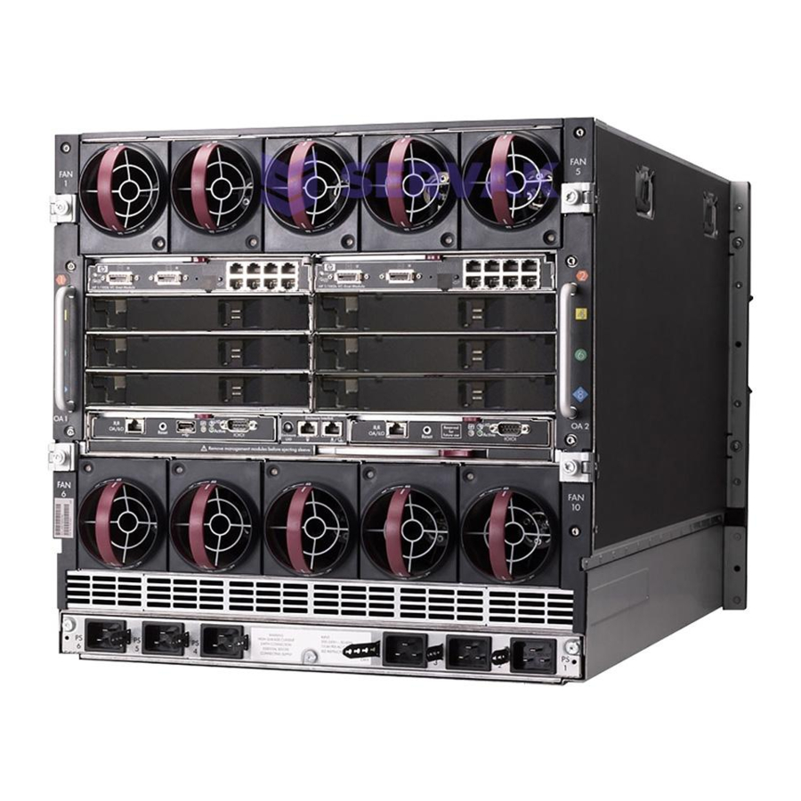
HP BladeSystem c7000 Quick Setup Instructions Manual
Hide thumbs
Also See for BladeSystem c7000:
- Setup and installation manual (103 pages) ,
- Maintenance and service manual (80 pages) ,
- Quickspecs (43 pages)
Table of Contents
Advertisement
Quick Links
Advertisement
Table of Contents

Summary of Contents for HP BladeSystem c7000
- Page 1 HP BladeSystem c7000 Enclosure Quick Setup Instructions Part Number 41 762-401...
-
Page 3: Site Requirements
Select an installation site that meets the detailed installation site requirements described in the server user guide on the Documentation Onboard A mandatory cover installed in CD and on the HP website (http://www.hp.com). Administrator with any unused Onboard KVM blank... -
Page 4: Installing The Enclosure
HP BladeSystem c7000 Enclosure Setup and Installation Guide. Remove all components from the front and rear of the enclosure, and then remove the rear cage. (Optional) Install the enclosure into a rack. See the HP BladeSystem c7000 Enclosure Rack Template. For rack-free installations, omit this step. -
Page 5: Half-Height Device Bay Numbering
Half-height device bay numbering Install the rear cage into the enclosure, close the hinges, and tighten the thumbscrews. Power supply bay numbering Enclosure bay identification Fan bay numbering Before installing front or rear components into the enclosure, review enclosure bay numbering for each component. Full-height device bay numbering Installing the front components CAUTION: To prevent improper cooling and thermal... - Page 6 Install only one type of power supply in a single enclosure. If your HP BladeSystem c7000 Enclosure is equipped with a three-phase power configuration, you need six power supplies. To install a power supply: To gain access to all power supply bays, slide the HP BladeSystem Insight Display to the right or left as needed.
-
Page 7: Connecting The Cables
Installing the rear components Install an Onboard Administrator with KVM blank into any unused Onboard Administrator with KVM bay. CAUTION: To prevent improper cooling and thermal damage, do not operate the enclosure unless all bays are populated with a component or a blank. Install fans in even-numbered groups, based on the total number of blades installed in the enclosure: Four fan configuration—Fan bays 4, 5, 9, and 10 are used... -
Page 8: Mapping To Interconnect Ports
Connects to Comments enclosure link-down port on the bottom linked enclosure is interconnect unused. bay/port NOTE: The HP BladeSystem c-Class enclosure link ports Embedded NIC 1 1/Port N One or two are not compatible with the HP BladeSystem p-Class single-wide... -
Page 9: Mapping Bl2X220C Blades
Connection Port number Connects to Comments Connection Port number Connects to Comments interconnect interconnect bay/port bay/port Mezzanine slot 4x port 1 3/Port N NIC 1 1/Port N+8 One or two • 1—4x cards double-wide single-wide NIC 2 2/Port N+8 interconnect Ethernet NIC 3 1/Port N... - Page 10 Device bay crosslinks To support network connections for specific signals, install an interconnect module in the bay corresponding to the embedded NIC or Device bay crosslinks are wired between adjacent horizontal device mezzanine signals. bay pairs. Interconnect device mapping for double dense server blades The following table lists the available configurations for double dense server blades installed in device bay N (1-16).
-
Page 11: Installing Interconnect Modules
Installing interconnect modules Powering up the enclosure Single-phase power configuration For a single phase power configuration: Connect the AC power cables to the power connectors on the rear of the enclosure corresponding to the power supply that was populated on the front of the enclosure. Be sure each power cable is securely attached to the power connectors. - Page 12 Turn on the AC circuit breakers that power the power cables installed in the enclosure. The installation is complete. Setting up the HP BladeSystem Insight Display To identify the enclosure, the rear enclosure UID light and the background of the Insight Display are illuminated blue when the enclosure is powered on initially.
- Page 13 HP Service Pack for ProLiant (SPP) from the HP website (http://www.hp.com/go/spp/download). The Smart Update Firmware DVD ISO is also available at the download tab on the HP website (http://www.hp.com/go/foundation). For information on using these installation methods, see the HP website (http://www.hp.com/go/ilo).
-
Page 14: Troubleshooting Resources
DVD-ROM drive and reboot the server. You might have to obtain additional drivers and firmware from the SPP download site (http://www.hp.com/go/spp/download). For more information, download the HP Service Pack for ProLiant (SPP) from the HP website (http://www.hp.com/go/spp/download). Troubleshooting resources The HP BladeSystem c-Class Enclosure Troubleshooting Guide provides procedures and solutions for troubleshooting HP BladeSystem c-Class enclosures. - Page 16 © Copyright 2006, 2011 Hewlett-Packard Development Company, L.P. The information contained herein is subject to change without notice. The only warranties for HP products and services are set forth in the express warranty statements accompanying such products and services. Nothing herein should be construed as constituting an additional warranty. HP shall not be liable for technical or editorial errors or omissions contained herein.


