Sony RM-IP10 Operating Instructions Manual
Ip remote controller
Hide thumbs
Also See for RM-IP10:
- Operating instructions manual (84 pages) ,
- Operation manual (44 pages)

Related Manuals for Sony RM-IP10


Summary of Contents for Sony RM-IP10
- Page 1 4-450-997-17(1) IP Remote Controller Operating Instructions _____ Mode d’emploi____________ Manual de instrucciones ___ RM-IP10 © 2012 Sony Corporation...
- Page 2 In the case that interference should occur, consult your nearest authorized Sony service facility. WARNING Use the Sony AC power adapter provided with this For the customers in Europe equipment as a power supply source. Any other power This apparatus shall not be used in the residential area.
-
Page 3: Table Of Contents
..........19 Using the Function Stored in the Memory of the Data and security RM-IP10 ............... 20 • SONY WILL NOT BE LIABLE FOR Setting a limit on the maximum panning/tilting DAMAGES OF ANY KIND RESULTING speed ............... 20 FROM A FAILURE TO IMPLEMENT PROPER To Return to the Factory Setting ...... -
Page 4: Getting Started
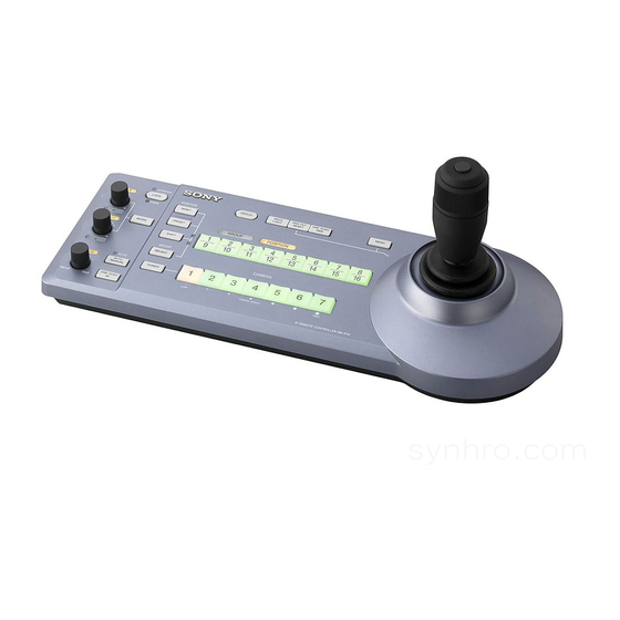
Getting Started Overview Features Precautions Operate up to 112 cameras* by using the IP Operating or storage location connection You can operate up to 112 cameras by using a Operating or storing the unit in the following locations commercially available switching hub. The cameras can may cause damage to the unit: be operated by up to five IP remote controllers •... -
Page 5: Location And Function Of Parts
You cannot use the multiple communication methods of Parts simultaneously. The optical three-axis joystick allows This manual is based on operation of the RM-IP10 when comfortable pan/tilt/zoom operations. used with a BRC series Color Video Camera. Easy operation of versatile camera... - Page 6 on the camera. For details, see “Functions of the R Functions of the R and B controls and B controls” on page 6. When the white balance adjustment mode is selected with the MODE button of this unit, the functions of the C BRIGHT/B control R control and B control change according to the white When the brightness adjustment mode is...
- Page 7 G ONE PUSH AF button For details, refer to the Operating Instructions This button is enabled when MANUAL is selected supplied with that camera. with the AUTO/MANUAL button. Press the button • The backlight compensation and spotlight to perform the one-push auto focus function. compensation exposure mode of the BRC-H900 differ from the FULL AUTO exposure mode.
- Page 8 R SHIFT button and indicators Rear When pressing the SHIFT button, the lower indicator lights and the GROUP/POSITION buttons can be used for group/position numbers 9 to 16. If you release the SHIFT button, the upper indicator will light and the GROUP/POSITION buttons can be used for group/position numbers 1 to MODE RS-232C...
- Page 9 Bottom Notes • For safety, do not connect the connector for ea es peripheral device wiring that might have excessive voltage to this port. Follow the instructions for this port. • When you connect the LAN cable of the unit to peripheral device, use a shielded-type cable to prevent malfunction due to radiation noise.
- Page 10 Switch Switch Mode Switch Switch Mode – When the selected camera ON AIR TALLY mode: does not receive its own The following actions are number command from the performed for the number that is TALLY/CONTACT input from the TALLY/ connector: CONTACT connector only while The selected camera receiving the commands.
- Page 11 EXPAND (expansion method) Switch Switch Setting • When treating the TALLY/CONTACT connector as input: Setting 4: Each time you press Treats the terminal 1 to 7 as a binary number. the LOCK button, the lock Accepts as number 1 when the terminal 1 is function changes as follows: earthed and terminals 2 to 7 is open.
-
Page 12: Connections And Operations
• The IP address is set at the factory to Connections and Operations 192.168.0.10 for RM-IP10, and 192.168.0.100 for BRBK-IP10/BRBK-IP7Z. • Network delay happens when stacking the switching hubs. We recommend that stacked switching hubs are limited to two. Connections •... - Page 13 Connecting example Default settings for the IP connection Set the DIP 2 switch 8 to ON to perform settings of BRC-H900 1 2 3 1 2 3 4 5 6 7 8 9 cameras and IP remote controllers (Setting update IR SELECT VISCA RS-422 RGB/COMPONENT...
-
Page 14: Connecting Cameras Equipped With Visca Rs-232C Connector
Import type) enable control of up to seven cameras with a single function. RM-IP10 IP Remote Controller. (An RS-232C cable “Unknown camera is assigned.” is displayed should be used up to 15 m (49.2 feet).) on “RM-IP Setup Tool”... -
Page 15: Connecting Cameras Equipped With Visca Rs-422 Connector
Note to AC AC power adaptor outlet (supplied) When connecting with the VISCA RS-232C connector, make sure that DIP 1 switch 1 is set to ON, and DIP 1 AC power switch 2 is set to OFF (page 9). cord (supplied) To assign camera addresses Before operating, you must assign the camera addresses... -
Page 16: Connecting The Bru-Sf10 Optical Multiplex Unit
* The VISCA RS-422 connection is also available if you use the Connecting the BRU-SF10 Optical VISCA RS-422 connectors. Multiplex Unit For other cameras, you can also use a matching Optical You can control the camera using this unit via the BRU- Multiplex Unit to control the camera with this unit. -
Page 17: Connecting A Video Switcher
Connecting a video switcher Turning on the Power Use a commercially available contact-control type video switcher to switch between the multiple camera signals to be output. Third to seventh BRC-H900 JOYSTICK VALUE LOCK BLACK PAN-TILT ONE PUSH POSITION GROUP MENU LIGHT RESET KNOB... -
Page 18: Storing The Camera Settings In Memory - Presetting Feature
To turn on/off the camera using this unit Storing the Camera As long as the camera is connected to an AC outlet, you can turn the camera on or off with the POWER button on Settings in Memory this unit. While holding down the POWER button, press the –... -
Page 19: Setting The Speed Of The Camera Moving To A Preset Position
We recommend that you check the stored settings Setting the speed of the camera by recalling the preset. moving to a preset position* To recall the stored settings * The moving speed is stored in the internal memory of Press the GROUP/POSITION button in which you have the camera. -
Page 20: Using The Function Stored In The Memory Of The Rm-Ip10
GROUP/POSITION the RM-IP10 button. The following function for panning/tilting operations with the RM-IP10 is stored in the memory of this unit. Setting a limit on the maximum panning/tilting speed You can limit the panning/tilting speed obtained when you incline the joystick at the maximum angle. -
Page 21: To Return To The Factory Setting
To Return to the Factory Setting Turn the unit on while holding down the RESET and SELECT buttons. When the unit is turned on, buttons and indicators flash as follows: Yellow (1 second) t Green (1 second) t Red (1 second) t The GROUP/POSITION button that was selected when the unit was turned off last (with the upper or lower indicator beside of the SHIFT... -
Page 22: Appendix
Appendix Troubleshooting Before bringing in your unit for service, check the following as a guide to troubleshoot the problem. If the problem cannot be corrected, consult with your Sony dealer. Symptom Cause Remedy The power of the unit is not turned on. -
Page 23: Specifications
LAN: RJ-45 (8-pin), 10BASE-T/ OR FOR ANY OTHER REASON 100BASE-TX automatically WHATSOEVER. detected • SONY WILL NOT BE LIABLE FOR CLAIMS OF Control signal format (for RS-232C/RS-422 ANY KIND MADE BY USERS OF THIS UNIT communication) OR MADE BY THIRD PARTIES. -
Page 24: Dimensions
Dimensions Pin Assignments VISCA RS-232C output connector (mini DIN 8- pin, female) JOYSTICK VALUE LOCK BLACK PAN-TILT ONE PUSH RS-232C POSITION GROUP MENU LIGHT RESET KNOB RESET – GROUP POSITION PRESET MODE BRIGHT SHIFT – GROUP SELECT CAMERA AUTO FOCUS AUTO POWER MANUAL... -
Page 25: Using The Visca Rs-422 Connector Plug
TALLY/CONTACT connector (connector plug, Using the VISCA RS-422 connector 9-pin) plug TALLY/CONTACT Grasp both ends of the VISCA RS-422 connector plug and pull it out as shown in the illustration. Pin No. Function CAMERA1 CAMERA2 CAMERA3 CAMERA4 CAMERA5 Insert a wire (AWG Nos. 28 to 18) into the desired CAMERA6 wire opening on the plug, and tighten the screw for CAMERA7... -
Page 26: Example Connection Of Tally/Contact Connector For Input
If an inrush or reverse voltage that is over the rating is Switch or relay connection applied to the TALLY/CONTACT connector, it may cause a malfunction, smoke, or fire. External device RM-IP10 + 3.3 V Input Waveform of TALLY/ CONTACT Connector 10 kΩ... -
Page 27: License
License This software partially supports component uIP. Therefore the following license conditions apply. Copyright (c) 2001-2006, Adam Dunkels and the Swedish Institute of Computer Science All rights reserved. Redistribution and use in source and binary forms, with or without modification, are permitted provided that the following conditions are met: 1.