Advertisement
Quick Links
These instructions are written assuming that you will have ample room around Opener to perform this repair. Some rare instances
will require removal of the unit from it's mounting hardware and repair made on a bench or floor. Refer to your Owners Manual or
Installation Poster for proper assembly and carefully read and understand all warnings and cautions pertaining to your unit.
!
WARNING
BE SURE ELECTRICAL POWER HAS BEEN DISCONNECTED FROM THE OPENER PRIOR TO REMOVING THE MOTOR COVER.
WARNING
!
ANY AND ALL REPAIRS MADE TO THIS UNIT MUST BE PERFORMED WITH THE DOOR DISCONNECTED FROM THE OPENER AND IN THE
CLOSED POSITION.
Tools required: Standard slotted and Phillips head screwdrivers, small slotted screwdriver, 5/16" nutdriver.
CLOSE DOOR PRIOR TO REPAIR.
1. Remove power from operator.
2.
Press down on tabs to remove lens.
3.
Remove light bulbs.
4.
Note locations and remove BWC (Basic Wall Control) and STB (Safe-T-Beam
tabs to remove wires. FIG. 1.
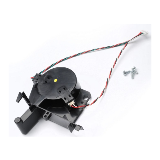
5.
If equipped, unplug and remove battery backup (BBU) from back of motor housing. Fig. 2.
FIG. 1
39272S.S
Scan code or visit
http://www.openerserviceassistant.
com/39272S.S & 39272T.S .htm
to view a video of this repair.
39565503416
24V DC Opto Replacement
For Chain & Belt Operators
39272T.S
) wires. Use small screwdriver to press in on orange
®
FIG. 2
PARTS REMOVED FOR CLARITY
09/2016
Advertisement

Related Manuals for Genie 39272T.S

Summary of Contents for Genie 39272T.S
- Page 1 If equipped, unplug and remove battery backup (BBU) from back of motor housing. Fig. 2. FIG. 1 39272S.S 39272T.S FIG. 2 PARTS REMOVED FOR CLARITY Scan code or visit http://www.openerserviceassistant. com/39272S.S & 39272T.S .htm to view a video of this repair. 39565503416 09/2016...
- Page 2 Using a 5/16” nut driver or common screw driver, remove the 2 opener cover screws and remove opener cover. FIG-3A Note the locations and disconnect lights, transformer primary, AC power, red & black motor wires, transformer secondary, and encoder harnesses. FIG. 4 Using a 1/4”...
- Page 3 Wire color legend BBU B-R Encoder W-G-B-B-R-R W=White G=Green B=Black BL=Blue R=Red Y=Yellow Transformer Secondary R-Y-W Motor Wire Black Motor Wire Red AC Line IN. B-W Transformer Primary. B-B Light Socket. W-B FIG. 4 Connector Detail FIG. 6 Parts removed for clarity FIG.