
Summary of Contents for Smith Little Torch
- Page 1 OM-263 357A 2013−06 Processes Oxy-Fuel Soldering Welding Heating The Little Torch OWNERS MANUAL File: Accessory Form 4164 Rev 2013-06...
-
Page 2: Table Of Contents
TABLE OF CONTENTS SECTION 1 − SAFETY PRECAUTIONS - READ BEFORE USING ..1-1. Symbol Usage ..........1-2. -
Page 3: Section 1 − Safety Precautions - Read Before Using
SECTION 1 − SAFETY PRECAUTIONS - READ BEFORE USING OXY FUEL 2013-06 Protect yourself and others from injury — read, follow, and save these important safety precautions and operating in- structions. 1-1. Symbol Usage DANGER! − Indicates a hazardous situation which, if not avoided, will result in death or serious injury. - Page 4 READ INSTRUCTIONS. Read and follow all labels and the Owner’s Manual carefully be- fore installing, operating, or servicing equipment. Read the safety information at the beginning of the manual and in each section. Use only genuine replacement parts from the manufacturer. Perform maintenance and service according to the Owner’s Manuals, industry standards, and national, state, and local codes.
- Page 5 LIGHT RAYS can burn eyes and skin. Light rays from the welding and cutting process produce intense visible and invisible (ultraviolet and infrared) rays that can burn eyes and skin. Sparks fly off from the weld. Wear approved face protection fitted with a proper shade of filter lenses to protect your face and eyes from light rays and sparks when welding, cutting, or watching (see ANSI Z49.1 and Z87.1 listed in Safety Standards).
- Page 6 Perform work only in an area with a fireproof floor (concrete). Do not heat concrete because it may expand and explode violently. Perform work on a fireproof surface. Use heat resistant shields to protect nearby walls and flooring. Do not use if grease or oil is present on equipment or if equipment is damaged.
-
Page 7: California Proposition 65 Warnings
CYLINDERS can explode if damaged. Compressed gas cylinders contain gas under high pressure. If damaged, a cylinder can explode. Since gas cylinders are normally part of the welding or cutting process, be sure to treat them carefully. Protect compressed gas cylinders from excessive heat, mechani- cal shocks, physical damage, slag, open flames, and sparks. -
Page 8: Principal Safety Standards
1-4. Principal Safety Standards Safety in Welding, Cutting, and Allied Processes, ANSI Standard Z49.1, is available as a free download from the American Welding Society at http://www.aws.org or purchased from Global Engineering Documents (phone: 1-877-413-5184, website: www.global.ihs.com). Safe Practices for the Preparation of Containers and Piping for Welding and Cutting, American Welding Society Standard AWS F4.1, from Global Engineering Documents (phone: 1-877-413-5184, website: www.global.ihs.com). -
Page 9: Section 2 − Introduction
Be sure all connections are tight and there are no leaks in the system. This booklet offers basic information regarding the Little Torch. Given reasonable care, the torch will provide trouble-free use for many years. -
Page 10: Section 5 − The Torch System
Fuel: The fuel for combustion may be the regulator itself if enough heat is produced to reach the kindling temperature of the regulator’s compo- nents. Kindling Temperatures: Enough heat may be generated to ignite the regulator components by the friction created when recompressing high-pressure oxygen. -
Page 11: Section 6 − Frequently Asked Questions
For your protection, use only genuine Smith Equipment hose and re- placement parts. Smith Equipment replacement hoses come with step–by–step replacement instructions and a tool for securing the brass ferrules over the hose ends. -
Page 12: Section 7 − Using Torch With Disposable-Type Cylinders
concentrated, pinpoint high temperature flame (about 6000°F/3316°C) whereas the other gases tend to spread the heat produced throughout the outer flame. The acetylene flame produces soot during combustion and the LP gases tend to burn much cleaner. Acetylene gas is lighter than air and in the event of a gas leak it will tend to dissipate in the atmos- phere with any air flow. -
Page 13: Disposable Compressed Gas Cylinders
Do not splice or use damaged oxy-fuel hoses. Use only the hoses that are supplied by Smith Equipment. These hoses transport low-pressure gases from the regulator to the torch tips. The hoses are color coded (green) for oxygen and (red) for fuel gas. -
Page 14: Activating The System
7-4. Activating The System Open the regulator valves completely by turning knobs clockwise. Notice the arrows on top of the knobs. 7-5. Purging The System Always purge gas from the system before lighting torch to pre- vent a possible mixed-gas explosion. Purge gas in a well venti- lated area and away from flame or sparks. -
Page 15: Extinguishing The Torch Flame
Use only compressed gas cylinders that are approved by the Depart- ment of Transportation (DOT) with this equipment. The torch will operate on cylinders that are available from Smith Equipment or from your local welding supply dealer. 8-1. Industrial-Type Cylinder Information... -
Page 16: Installing Regulators
Do not splice or use damaged oxy-fuel hoses. Use only the hoses that are supplied by Smith Equipment. These hoses transport low-pressure gases from the regulator to the torch tips. The hoses are color coded (green) for oxygen and (red) for fuel gas. -
Page 17: Adjusting Regulator Pressures And Purging The Hoses
Do not activate the system with the regulator pressure adjust- ing handle turned in. This condition can allow high pressure gas to damage the internal parts of the regulator which can re- sult in a fire or explosion. Turn the oxygen regulator pressure adjusting handle counterclock- wise until no spring pressure is felt on the pressure adjusting han- dle. -
Page 18: Selecting And Installing A Tip
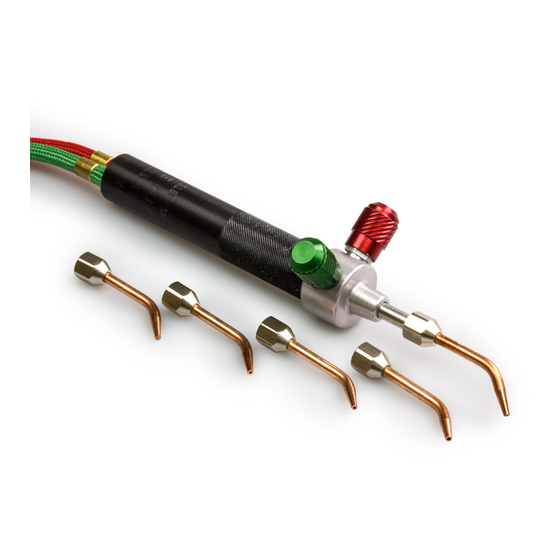
161-013 Figure 3. Testing Equipment For Leaks 8-7. Selecting And Installing A Tip Fully open the oxygen and fuel gas regulators (turn handles clock- wise). Select the desired tip. Tip sizes are represented by a number (2−7) stamped on the copper section. Size 7 produces the largest flame. It is recommended that the size 2 tip not be used for gas other than acetylene or hydrogen. -
Page 19: Lighting And Adjusting Torch When Using Alternate Fuel Gases
8-9. Lighting And Adjusting Torch When Using Alternate Fuel Gases (Propane, Propylene, Natural Gas) The following instructions are adjustment procedures for the torch when using alternate fuel gases. This equipment is designed to operate at a set volume of gas for each tip. Follow the set-up instructions explained in Sections 8-2 thru 8-7 before lighting the torch. -
Page 20: Section 9 − Hose Replacement
SECTION 9 − HOSE REPLACEMENT Replace hoses at the first sign of any defects, flaws, or dam- age. The hoses should otherwise be replaced every four years. Inspect hoses for damage or leaks before each operation. Do not allow hoses to come in contact with hot metal, molten sol- der, or corrosive chemicals. -
Page 21: Section 10 − Regulators
Repeat instructions for red hose. Use an approved oil-free leak detection fluid to locate possible leaks. Close torch valves and pressurize torch (both hoses) to 10–12 psig (69–83 kPa). Immerse torch in water and check connections and torch for leaks (bubbles). If a leak is not observed, the torch is now ready to use. -
Page 22: Section 11 − Technical Data
SECTION 11 − TECHNICAL DATA 11-1. Tip Specifications Straight, Curved, And Twin-Flame Torch Tips Gas Pressure Orifice Consumption Recom’d psig (kPa) Diameter Each Gas* Fuel Gas Size w/Oxygen in. (mm) /hr (L/hr) Oxygen Fuel .006 0.11074 Acetylene, (0.15) (13.8) (13.8) (3.1) Hydrogen .011... -
Page 23: Fuel Gas And Flame Characteristics
11-2. Fuel Gas And Flame Characteristics Settings: Neutral Flame Flame Settings Acetylene − Oxygen Neutral Flame After igniting, open acety- lene valve until soot disap- Even Mixture of Fuel and Oxygen pears from end of flame. Add oxygen until the feather Carburizing (Reducing) Flame shown on the right just dis- Excess Fuel Gas... -
Page 24: Section 12 − Accessories
SECTION 12 − ACCESSORIES Straight Tip Size 4 Twin Flame Tip Sizes 4–6 Propane/Natural Gas Melting Tip Melts To 3 oz. Silver Stock No. 13717 Acetylene/Hydrogen Melting Tip Melts to 3 oz. Gold Or Silver Stock No. 13-662 Curved Tips Sizes 2–7 Magnetic Stand Stock No. - Page 25 Low-Pressure Blanketing Regulators, Gas Savers, Gas Mixers, and all other Oxy-Fuel Products SMITH BRANDED PRODUCTS The Little Torch, Quickbraze Torch, Handi-Heet/Silver Smith Torch 90 Days – Parts and Labor Corrosive Service Regulators Miller’s True Blue) Limited Warranty shall not apply to: Consumable components;...
- Page 26 authorized in writing by Miller in appropriate cases, (3) the reasonable cost of repair or replacement at an authorized Miller service station; or (4) payment of or credit for the purchase price (less reasonable depreciation based upon ac- tual use) upon return of the goods at customer’s risk and expense. Miller’s option of repair or replacement will be F.O.B., Factory at Appleton, Wisconsin, or F.O.B.
- Page 27 Notes OM-263 357 Page 25...
- Page 28 Miller Electric Mfg. Co. An Illinois Tool Works Company 1635 West Spencer Street Appleton, WI 54914 USA International Headquarters−USA USA Phone: 920-735-4505 Auto-Attended USA & Canada FAX: 920-735-4134 International FAX: 920-735-4125 For International Locations Visit www.MillerWelds.com ORIGINAL INSTRUCTIONS − PRINTED IN USA E2013 Miller Electric Mfg.