
Related Manuals for Carrier CMCT Series


Summary of Contents for Carrier CMCT Series
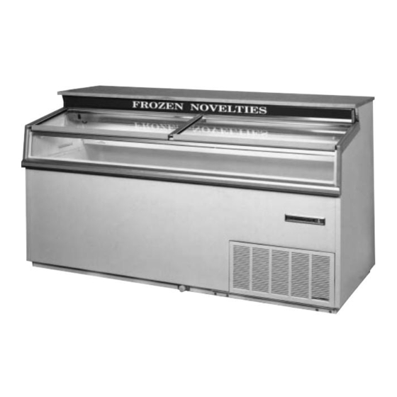
- Page 1 CARRIER COMMERCIAL REFRIGERATION, INC. Providing BEVERAGE-AIR • FRIGIDAIRE • KELVINATOR • UNIVERSAL NOLIN Products/Services SERVICE & INSTALLATION MANUAL Frozen Food & Ice Cream Merchandisers CMCT 2/03 51-1021-01...
- Page 2 If additional information is necessary, call the factory. Our toll free number is 1-800-684-1199. Technical assis- tance engineers are willing to assist you in any way possi- ble. Office hours are from 8:00a.m. to 5:30 p.m., Eastern Standard Time. Important information is contained in this manual which should be retained in a convenient location for future reference.
- Page 3 SECTION I Introduction...
- Page 4 CMCT Merchandisers – Introduction These cabinets are produced for the merchandising of frozen food and ice cream markets. They range in size from 4' to 10' in length. Operating ambients range from 70ºF. to 85ºF. with cavity temperatures at load line between 0ºF. to -20ºF. Except for routine cleaning, these cabinets will require little maintenance.
-
Page 5: Table Of Contents
TABLE OF CONTENTS INTRODUCTION PARTS LISTS Introduction ..............3 CMCT Cabinet Exterior Parts ID ........40 Table of Contents ............4 Parts List CMCT-4, 6, 8 & 10..........41 Specifications & Illustrations ..........5 Parts List EMCT-4, 6 & 8..........42 Handling &... - Page 6 Specifications - Specifications Subject to Change without Notice. CMCT-4 CMCT-6 CMCT-8 CMCT-10 Temperature Range 0° to -20°F 0° to -20°F 0° to -20°F 0° to -20°F Insulation ⁄ " Urethane Foam in Place ⁄ " Urethane Foam in Place ⁄ "...
-
Page 7: Handling & Installation
2. Notify the transportation company’s office to request Remove the front grill from cabinet. Remove front hold an inspection. Carrier claim policies usually require down bolts and pull unit out of cabinet. Remove ship- inspections to be made within 15 days of delivery. -
Page 8: Cleaning Instructions
CLEANING INSTRUCTIONS DESCRIPTION OF REFRIGERATION SYSTEM: CONDENSING UNIT CLEANING THE CABINET EXTERIOR All CMCT cabinets are equipped with Copelametic Wipe the exterior occasionally with a cloth dampened in compressors utilizing 404A refrigerant: mild detergent water; rinse, and wipe dry with a soft, 1/2 HP on the CMCT-4 and CMCT-6 dry cloth. - Page 9 Defrosting is initiated by the time clock and terminated Any time the system has been opened and NOTE: by a temperature thermostat set to close at 76°F. When exposed to the atmosphere, a new drier this thermostat closes, it energizes a solenoid in the should be installed, system completely evacuated, and time clock which in turn trips the clock mechanism off recharged to the specified refrigerant and amount list-...
- Page 10 CMCT ELECTRICAL DATA CMCT-4 CMCT-8 OHMS WATTS AMPS VOLTS OHMS WATTS AMPS VOLTS Def. Heater on Bottom side Def. Heater on Bottom side 24.7 11.8 1200 of Top Coil of Top Coil Control Bellows Heater below Control Bellows Heater below 1600 .075 1600...
- Page 11 REFRIGERATION/ELECTRICAL SPECIFICATIONS CMCT (404A) CABINET START MODEL MFG. MODEL VOLTS AMPS AMPS CMCT-4 Copeland KAGB-005E-IAA-222 CMCT-6 Copeland KAGB-005E-IAA-222 CMCT-8 Copeland KAJB-007E-IAA-222 12.0 CMCT-10 Copeland KALB-010E-CAV-221 230/208 33.5 REFRIGERATION CYCLE (80° Ambient) CABINET REFRIG. DEFROST CAP . CONTROL CAVITY MODEL CYCLE CYCLE REFRIG.
- Page 12 ECMCT REFRIGERATION/ELECTRICAL DATA Export Models (R-404A) ECMCT-4 ECMCT-6 OHMS WATTS AMPS VOLTS OHMS WATTS AMPS VOLTS Def. Heater on Bottom side Def. Heater on Bottom side 72.4 of Top Coil of Top Coil Control Bellows Heater below Control Bellows Heater below 5375 5375 Def.
- Page 13 WIRING DIAGRAM – 00-1667-00 CMCT-4, 6, & 8 INTRODUCTION...
- Page 14 WIRING DIAGRAM – 00-1670-00 CMCT-10 INTRODUCTION...
- Page 15 WIRING DIAGRAM – 00-1934-00 ECMCT-4, 6, & 8 (Export Models) INTRODUCTION...
-
Page 16: Lamp Wiring Detail (Upper Raceway)
LAMP WIRING DETAIL – Upper Raceway (Typical) INTRODUCTION... -
Page 17: Maintenance & Repair
SECTION II Maintenance & Repair... -
Page 18: Cabinet Temperature Control
CABINET TEMPERATURE CONTROL Disconnect the power supply before CAUTION: COLD OUT NORMAL OUT NORMAL IN WARM IN servicing the cabinet. -30°F -23°F -15°F -2°F Remove the front grill. TERMINALS: .25 QUICK CONNECT TAB The control is located in the machine compartment in the upper righthand corner, just above the electrical CAP TUBE LENGTH: 24"... -
Page 19: Electrical Box Layout
ELECTRICAL BOX LAYOUT Disconnect the power supply before CAUTION: servicing the cabinet. The electrical box can be accessed by removing the front grill. The electrical box can be pulled out for component troubleshooting. The following components are located within the box. 1. -
Page 20: Defrost Timer Layout
DEFROST TIMER LAYOUT After the cabinet is connected to proper voltage supply, the time clock should be set to the correct time of day by turning the inner knob counterclockwise until the correct time is opposite the time indicator on the clock. The time clock is set to go into defrost once every 24 hours. -
Page 21: Cabinet Electrical Supply
CABINET ELECTRICAL SUPPLY The connection points can be accessed by removing Wiring and connections in power IMPORTANT: the rear grill. Models CMCT-4 up through CMCT-8 have supply system must meet all applica- 115V service cords. CMCT-10 is 230V, hard wire con- ble (local and national) electrical codes. -
Page 22: Condensing Unit Assembly
CONDENSING UNIT ASSEMBLY This product utilizes the pull out feature on its low tem- perature applications. This is to aid service personnel in the event service is needed. Disconnect the power supply before CAUTION: servicing the cabinet. 1. Remove front grill. 2. -
Page 23: Condensing Unit Layout
CONDENSING UNIT LAYOUT MAINTENANCE & REPAIR... -
Page 24: Unit Compartment - Rear
UNIT COMPARTMENT – REAR CMCT-10 models still use fin and tube NOTE: condensers. 1. Accordian Coil 2. Process Tube Evaporator 3. Suction Line 4. Cap Tube Inlet MAINTENANCE & REPAIR... -
Page 25: Evaporator Tubing Illustration
EVAPORATOR TUBING ILLUSTRATION EVAPORATOR TANK WRAP – RH SIDE VIEW: Evaporator inlet tube NOTE: on top row. 1. Tank Wrap Inlet 2. #2 Pass 3. #3 Pass 4. Thermostat Bulb Well 5. Condensate Drain TANK WRAP – FRONT SIDE 6. #1 Pass 7. -
Page 26: New Lubricants
NEW LUBRICANTS In switching from refrigerant 502 to refrigerant 404A, the compressor lubricants had to be changed. Oils used in the compressors in the past were mineral based. The new oils used are polyol esters. Special consideration must be made when handling these oils. Processing procedures must be more rigorous to avoid absorbing moisture. -
Page 27: Back Pressure Valve
BACK PRESSURE VALVE – #1 These models are equipped with a back pressure valve. The purpose of this valve is to limit the suction pressure at the compressor during initial cabinet start up and start up after a defrost cycle. This valve is set at 10 PSIG and should not be changed. -
Page 28: Light Channel Assembly
LIGHT CHANNEL ASSEMBLY – Component Identification Disconnect the power supply before CAUTION: servicing the cabinet. Wiring from the pull out electrical box is connected via a wiring harness to the upper lighting channel which houses the following components: 1. Product Reflector 4. - Page 29 BAFFLE HEATER COMPONENT IDENTIFICATION & REMOVAL INSTRUCTIONS 1. Baffle Heater 2. Light Switch 3. Light Receptacle – Lefthand side When light switch is ON, baffle heater NOTE: is de-energized. Disconnect the power supply before CAUTION: servicing the cabinet. The baffle heater is located just behind the light fixture at the warm air intake to coil.
-
Page 30: End Panel Breaker & Heater Removal
END PANEL BREAKER & HEATER REMOVAL Disconnect the power supply before CAUTION: servicing the cabinet. 1. Remove eight (8) screws in the end panel breaker (A) and pull breaker down and out. 2. Disconnect heater leads from end panel breaker heater (A) and pull end panel breaker out. - Page 31 REFRIGERATED UPPER SECTION COMPONENT IDENTIFICATION & REMOVAL INSTRUCTIONS 1. Defrost Heater Lead Connection 4. Defrost Heater 2. Air Baffle 5. Defrost Heater Retainer Bracket 3. Upper Fin Coil 6. Front Coil Housing Cover Bracket REMOVAL INSTRUCTIONS: Disconnect the power CAUTION: supply before servic- ing the cabinet.
-
Page 32: Upper Cross Section
UPPER CROSS SECTION – CMCT Models... -
Page 33: Front Glass Heater Replacement
FRONT GLASS HEATER REPLACEMENT Disconnect the power supply before CAUTION: servicing the cabinet. Photograph shows the electrical connection between the cabinet and the front glass heater. REMOVAL OF FRONT GLASS HEATER AND/OR END TRACK: 1. Remove glass lids. 2. Remove side arm trim (A) at both sides per detail ‘A’. - Page 34 CMCT Models The countertop can be raised in order to service various interior components, as shown below. 1. Product Reflector 4. Upper Electrical Component Housing 2. Defrost Heater Plug 5. Righthand Arm Heater Leads 3. Lamp MAINTENANCE & REPAIR...
-
Page 35: Countertop
EVAPORATOR COIL REMOVAL Disconnect the power CAUTION: supply before servicing the cabinet. A. Raise up the counter top. B. Remove screws along the back wall of the sub top. C. Remove the high air intake baffle located on the righthand side of the sub top. - Page 36 EVAPORATOR COIL REMOVAL – continued 10. Sub Top 11. Air Diverter 12. Defrost Termination Bulb Well The view below illustrates the evaporator coil and tube connections on the lefthand end of the cabi- net. Take care when reinstalling the coil housing cover.
-
Page 37: Troubleshooting Guide
CMCT TROUBLESHOOTING GUIDE The following is a guide to aid in the proper diagnosing After the coil reaches 76°F, it closes, energizing a of service problems. solenoid in the time clock which in turn trips the time clock mechanism off defrost. Should this thermostat High Head Pressure &... - Page 38 SECTION III Parts List...
- Page 39 CABINET EXTERIOR PARTS IDENTIFICATION CMCT Models 1. Vertical Trim Post (RH) 6. Center Track 11. Nameplate 2. End Track (LH) 7. Glass Lid 12. Front Bumper 3. Countertop 8. Glass Rail 13. Bumper Trim 4. End Trim 9. Front Glass 14.
- Page 40 DOMESTIC CMCT PARTS LIST – R-404 Parts List - CMCT's Description CMCT-4 CMCT-6 CMCT-8 CMCT-10 Compressor 16-0322-00 16-0322-00 16-0323-00 16-0324-00 Start Relay 17-0163-00 17-0163-00 17-0163-00 17-0167-00 Start Capacitor 17-0164-00 17-0164-00 17-0165-00 17-0168-00 Run Capacitor 17-0166-00 19-2678-00 Condenser Coil 51-0709-02 51-0709-02 51-0709-03 18-0533-00 Fan Motor...
- Page 41 EXPORT CMCT PARTS LIST – R-404 Export Parts List - CMCT's Description ECMCT-4 ECMCT-6 ECMCT-8 Compressor 16-0298-00 16-0298-00 16-0290-00 Start Relay 17-0167-00 17-0167-00 17-0167-00 Start Capacitor Run Capacitor 19-2678-00 19-2678-00 19-2678-00 Condenser Coil 51-0709-03 51-0709-03 51-0709-03 Fan Motor 19-0501-00 19-0501-00 19-0501-00 Fan Blade 19-0101-00...