Table of Contents
Advertisement
Quick Links
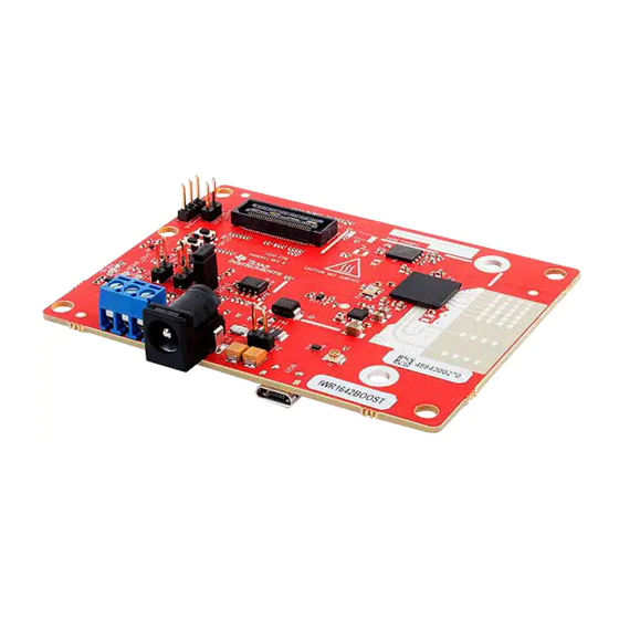
IWR1642 Evaluation Module (IWR1642BOOST)
The IWR1642 BoosterPack™ from Texas Instruments™ is an easy-to-use evaluation board for the
IWR1642 mmWave sensing device, with direct connectivity to the microcontroller (MCU) LaunchPad™
Development Kit. The BoosterPack contains everything required to start developing software for on-chip
C67x DSP core and low-power Arm
debugging as well as onboard buttons and LEDs for quick integration of a simple user interface.
1
1.1
1.2
1.3
......................................................................................................................
2
2.1
2.2
2.3
2.4
2.5
2.6
2.7
3
3.1
3.2
4
5
6
7
..................................................................................................................
8
Trademarks
BoosterPack, Texas Instruments, LaunchPad, Code Composer Studio are trademarks of Texas
Instruments.
Arm is a registered trademark of Arm Limited.
Windows is a registered trademark of Microsoft Corporation.
All other trademarks are the property of their respective owners.
SWRU521C - May 2017 - Revised May 2020
Submit Documentation Feedback
Single-Chip mmWave Sensing Solution
R4F controllers, including onboard emulation for programming and
®
...............................................................................................................
..........................................................................................................
.......................................................................................................
..........................................................................................................
.......................................................................................................
.................................................................................................
..........................................................................................................
.....................................................................................................
.............................................................................................................
...................................................................................
.........................................................................................
...........................................................................................................
.............................................................................................
....................................................................................................
............................................................................................................
IWR1642 Evaluation Module (IWR1642BOOST) Single-Chip mmWave
Copyright © 2017-2020, Texas Instruments Incorporated
SWRU521C - May 2017 - Revised May 2020
Contents
...........................................................
........................................................................
User's Guide
2
2
2
2
3
5
6
6
10
............................
11
12
18
21
21
21
21
22
23
23
23
1
Sensing Solution
Advertisement
Table of Contents

Related Manuals for Texas Instruments BoosterPack IWR1642


Summary of Contents for Texas Instruments BoosterPack IWR1642
-
Page 1: Table Of Contents
IWR1642 Evaluation Module (IWR1642BOOST) Single-Chip mmWave Sensing Solution The IWR1642 BoosterPack™ from Texas Instruments™ is an easy-to-use evaluation board for the IWR1642 mmWave sensing device, with direct connectivity to the microcontroller (MCU) LaunchPad™ Development Kit. The BoosterPack contains everything required to start developing software for on-chip... -
Page 2: Getting Started
Getting Started Introduction The IWR1642 BoosterPack from Texas Instruments is an easy-to-use evaluation board for the IWR1642 mmWave sensing device, with direct connectivity to the microcontroller (MCU) LaunchPad Development Kit. The BoosterPack contains everything required to start developing software for on-chip C67x DSP core and low-power ARM R4F controllers, including onboard emulation for programming and debugging as well as onboard buttons and LEDs for quick integration of a simple user interface. -
Page 3: Hardware
5-V Power 60-pin HD CAN-FD Connector Connector GPIO1_SW NRST_SW SOP Controls Figure 1. EVM (Front) SWRU521C – May 2017 – Revised May 2020 IWR1642 Evaluation Module (IWR1642BOOST) Single-Chip mmWave Sensing Solution Submit Documentation Feedback Copyright © 2017–2020, Texas Instruments Incorporated... - Page 4 Connector (J6) Connector (J5) PMIC Micro USB Connector Heat Sink Area Figure 2. EVM (Rear) IWR1642 Evaluation Module (IWR1642BOOST) Single-Chip mmWave SWRU521C – May 2017 – Revised May 2020 Sensing Solution Submit Documentation Feedback Copyright © 2017–2020, Texas Instruments Incorporated...
-
Page 5: Block Diagram
EN Control PGOOD Signal to From the MCU MCU for Power Sequencing Copyright © 2017, Texas Instruments Incorporated Figure 3. Block Diagram SWRU521C – May 2017 – Revised May 2020 IWR1642 Evaluation Module (IWR1642BOOST) Single-Chip mmWave Sensing Solution Submit Documentation Feedback... -
Page 6: Power Connections
3V3 and 5-V signal marking on the boards. Figure 5. 20-Pin BoosterPack Connectors IWR1642 Evaluation Module (IWR1642BOOST) Single-Chip mmWave SWRU521C – May 2017 – Revised May 2020 Sensing Solution Submit Documentation Feedback Copyright © 2017–2020, Texas Instruments Incorporated... - Page 7 IWR device and save power. The power up of the PMIC takes approximately 5 ms once the enable signal is made high. SWRU521C – May 2017 – Revised May 2020 IWR1642 Evaluation Module (IWR1642BOOST) Single-Chip mmWave Sensing Solution Submit Documentation Feedback Copyright © 2017–2020, Texas Instruments Incorporated...
- Page 8 HD connector, and Table 3 provides the connector information. Figure 6. HD Connector IWR1642 Evaluation Module (IWR1642BOOST) Single-Chip mmWave Sensing SWRU521C – May 2017 – Revised May 2020 Solution Submit Documentation Feedback Copyright © 2017–2020, Texas Instruments Incorporated...
- Page 9 Because the I/Os are not failsafe, the MCU must not drive any I/O signals to the IWR device before this I/O supply is stable to avoid leakage current into the I/Os. SWRU521C – May 2017 – Revised May 2020 IWR1642 Evaluation Module (IWR1642BOOST) Single-Chip mmWave Sensing Solution Submit Documentation Feedback Copyright © 2017–2020, Texas Instruments Incorporated...
-
Page 10: Pc Connection
XDS110 Class Application/User UART – UART1 port • XDS110 Class Auxiliary Data Port – MSS logger port Figure 8. COM Ports IWR1642 Evaluation Module (IWR1642BOOST) Single-Chip mmWave SWRU521C – May 2017 – Revised May 2020 Sensing Solution Submit Documentation Feedback Copyright © 2017–2020, Texas Instruments Incorporated... -
Page 11: Connecting The Boosterpack To The Launchpad Or The Mmwave-Devpack
NOTE: The DCA1000 EVM has internal DEVPACK functionality. For more information, see the DCA1000EVM Data Capture Card User's Guide. SWRU521C – May 2017 – Revised May 2020 IWR1642 Evaluation Module (IWR1642BOOST) Single-Chip mmWave Sensing Solution Submit Documentation Feedback Copyright © 2017–2020, Texas Instruments Incorporated... -
Page 12: Antenna
(H-plane Phi = 0 degrees) and elevation plane (E-plane Phi = 90 degrees) is shown by Figure IWR1642 Evaluation Module (IWR1642BOOST) Single-Chip mmWave SWRU521C – May 2017 – Revised May 2020 Sensing Solution Submit Documentation Feedback Copyright © 2017–2020, Texas Instruments Incorporated... - Page 13 Hardware www.ti.com Figure 11. Antenna Pattern SWRU521C – May 2017 – Revised May 2020 IWR1642 Evaluation Module (IWR1642BOOST) Single-Chip mmWave Sensing Solution Submit Documentation Feedback Copyright © 2017–2020, Texas Instruments Incorporated...
- Page 14 Azimuth Antenna Pattern TX1 TX1 to RX1 TX1 to RX2 TX1 to RX3 TX1 to RX4 IWR1642 Evaluation Module (IWR1642BOOST) Single-Chip mmWave SWRU521C – May 2017 – Revised May 2020 Sensing Solution Submit Documentation Feedback Copyright © 2017–2020, Texas Instruments Incorporated...
- Page 15 Azimuth Antenna Pattern TX2 TX2 to RX1 TX2 to RX2 TX2 to RX4 TX2 to RX3 SWRU521C – May 2017 – Revised May 2020 IWR1642 Evaluation Module (IWR1642BOOST) Single-Chip mmWave Sensing Solution Submit Documentation Feedback Copyright © 2017–2020, Texas Instruments Incorporated...
- Page 16 Elevation Antenna Pattern TX1 TX1 to RX1 TX1 to RX2 TX1 to RX3 TX1 to RX4 IWR1642 Evaluation Module (IWR1642BOOST) Single-Chip mmWave SWRU521C – May 2017 – Revised May 2020 Sensing Solution Submit Documentation Feedback Copyright © 2017–2020, Texas Instruments Incorporated...
- Page 17 Elevation Antenna Pattern TX2 TX2 to RX2 TX2 to RX1 TX2 to RX3 TX2 to RX4 SWRU521C – May 2017 – Revised May 2020 IWR1642 Evaluation Module (IWR1642BOOST) Single-Chip mmWave Sensing Solution Submit Documentation Feedback Copyright © 2017–2020, Texas Instruments Incorporated...
-
Page 18: Jumpers, Switches, And Leds
011 (SOP mode 2) = SOP 0 debug mode Figure 12 shows the SOP jumpers. Figure 12. SOP Jumpers IWR1642 Evaluation Module (IWR1642BOOST) Single-Chip mmWave SWRU521C – May 2017 – Revised May 2020 Sensing Solution Submit Documentation Feedback Copyright © 2017–2020, Texas Instruments Incorporated... - Page 19 Glows if there is any HW error in the IWR Nerr_OUT device GPIO_1 Glows when the GPIO is logic-1 SWRU521C – May 2017 – Revised May 2020 IWR1642 Evaluation Module (IWR1642BOOST) Single-Chip mmWave Sensing Solution Submit Documentation Feedback Copyright © 2017–2020, Texas Instruments Incorporated...
- Page 20 S2 switch. This switch is available on the board from Rev B onwards. Figure 20. S2 Switch to Select Between SPI or CAN Interface IWR1642 Evaluation Module (IWR1642BOOST) Single-Chip mmWave SWRU521C – May 2017 – Revised May 2020 Sensing Solution Submit Documentation Feedback Copyright © 2017–2020, Texas Instruments Incorporated...
-
Page 21: Design Files And Software Tools
Figure 21 shows how the L-brackets can be assembled. Figure 21. Vertical Assembly of EVM SWRU521C – May 2017 – Revised May 2020 IWR1642 Evaluation Module (IWR1642BOOST) Single-Chip mmWave Sensing Solution Submit Documentation Feedback Copyright © 2017–2020, Texas Instruments Incorporated... -
Page 22: Pcb Storage And Handling Recommendations
All ESD precautions must be taken while using and handling the EVM. IWR1642 Evaluation Module (IWR1642BOOST) Single-Chip mmWave SWRU521C – May 2017 – Revised May 2020 Sensing Solution Submit Documentation Feedback Copyright © 2017–2020, Texas Instruments Incorporated... -
Page 23: Regulatory Information
See Section 2.7.3 for LED information. References DCA1000EVM Data Capture Card User's Guide SWRU521C – May 2017 – Revised May 2020 IWR1642 Evaluation Module (IWR1642BOOST) Single-Chip mmWave Sensing Solution Submit Documentation Feedback Copyright © 2017–2020, Texas Instruments Incorporated... - Page 24 NOTE: Page numbers for previous revisions may differ from page numbers in the current version. Changes from B Revision (August 2018) to C Revision ....................Page ..........................• Added Note. Revision History SWRU521C – May 2017 – Revised May 2020 Submit Documentation Feedback Copyright © 2017–2020, Texas Instruments Incorporated...
- Page 25 TI products. TI’s provision of these resources does not expand or otherwise alter TI’s applicable warranties or warranty disclaimers for TI products. Mailing Address: Texas Instruments, Post Office Box 655303, Dallas, Texas 75265 Copyright © 2020, Texas Instruments Incorporated...