
Related Manuals for Yamaha RX-V620RDS


Summary of Contents for Yamaha RX-V620RDS
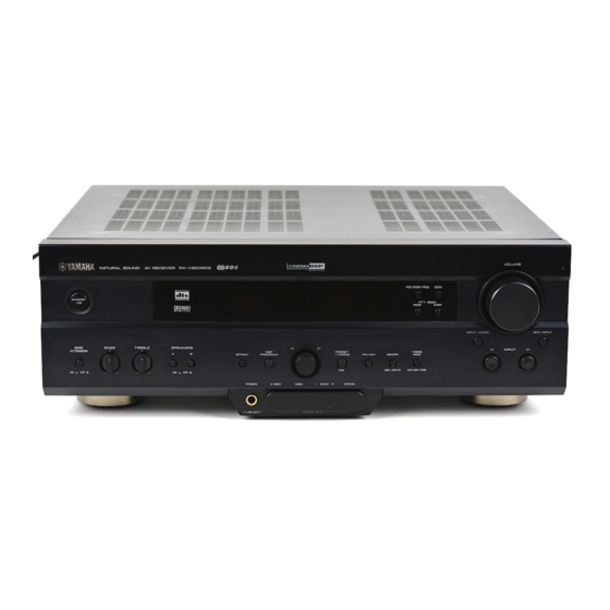
- Page 1 RX-V620RDS Natural Sound AV Receiver Ampli-tuner audio-vidéo OWNER’S MANUAL MODE D’EMPLOI BEDIENUNGSANLEITUNG BRUKSANVISNING MANUALE DI ISTRUZIONI MANUAL DE INSTRUCCIONES GEBRUIKSAANWIJZING...
- Page 2 Using this unit with a higher voltage than specified is dangerous and may cause fire, damage to this unit, and/or personal injury. YAMAHA will not be held responsible for any damage resulting from use of this unit with a voltage other than specified.
-
Page 3: Table Of Contents
INTRODUCTION INTRODUCTION FEATURES ... 2 GETTING STARTED ... 3 Checking the Package Contents ... 3 Installing Batteries in the Remote Control ... 3 CONTROLS AND FUNCTIONS ... 4 Front Panel ... 4 Remote Control ... 6 Description of the Numeric Buttons ... 7 Using the Remote Control ... -
Page 4: Features
Processing N DTS Decoder N Dolby Pro Logic Decoder N Dolby Digital Decoder N Hi-Fi DSP N CINEMA DSP: Combination of YAMAHA DSP Technology and Dolby Pro Logic, Dolby Digital or DTS N Virtual CINEMA DSP N SILENT CINEMA Sophisticated AM/FM Tuner... -
Page 5: Getting Started
Checking the Package Contents Check your package to make sure it has the following items. Remote control A/B/C/D/E Installing Batteries in the Remote Control Insert the batteries in the correct direction by aligning the + and – marks on the batteries with the polarity markings (+ and –) inside the battery compartment. -
Page 6: Controls And Functions
Front Panel D I G I T A L SURROUND STANDBY BASS BASS TREBLE SPEAKERS EXTENSION – – STANDBY/ON Turns on or sets this unit in the standby mode. When you turn on this unit, you will hear a click and there will be a 4 to 5-second delay before this unit can reproduce sound. - Page 7 BASS Adjusts the low-frequency response for the left and right main speakers. Turn the control to the right to increase or to the left to decrease the low-frequency response. TREBLE Adjusts the high-frequency response for the left and right main speakers. Turn the control to the right to increase or to the left to decrease the high-frequency response.
-
Page 8: Remote Control
CONTROLS AND FUNCTIONS Remote Control This section describes the basic operation of this unit with the remote control. First, set the selector dial to the AMP/ TUN position. See “REMOTE CONTROL FEATURES” for full details. Select the AMP/TUN position. A/B/C/D/E TV POWER TV VOLUME Switches the function of the numeric buttons to the DSP... -
Page 9: Description Of The Numeric Buttons
VOLUME +/– Increases or decreases the volume level. MUTE Mutes the sound. Press again to restore the audio output to the previous volume level. EFFECT Switches the effect speakers (center and rear) on and off in the following cases: • When the selector dial is set to the DSP/TUN position. •... -
Page 10: Using The Remote Control
CONTROLS AND FUNCTIONS I When selecting a preset station number Set code number “0023” in the AMP/TUN (or DSP/TUN) position. See “Setting the Manufacturer Code” for setting the code. Set the selector dial to the AMP/TUN (or DSP/TUN) position. You can select a preset station number directly with the numeric buttons (1 to 8). -
Page 11: Front Panel Display
Front Panel Display V-AUX VCR2/DVR VIRTUAL DIGITAL DOLBY DIGITAL PRO LOGIC DTS PRO LOGIC t indicator Lights up when the built-in DTS decoder is on. VIRTUAL indicator Lights up when using Virtual CINEMA DSP. g and o indicators Light up according to the type of Dolby signals this unit is reproducing. -
Page 12: Rear Panel
CONTROLS AND FUNCTIONS Rear Panel DIGITAL INPUT TUNER AM ANT GND FM ANT COAXIAL 75 UNBAL. OPTICAL D-TV/CBL 6CH INPUT D-TV/CBL IN VCR 1 OUT MAIN SURROUND CENTER MD/CD-R SUB WOOFER OPTICAL MD/CD-R IN(PLAY) OUT(REC) DIGITAL PHONO MD/CD-R D-TV/CBL OUTPUT AUDIO SIGNAL DIGITAL OUTPUT jacks DIGITAL INPUT jacks... -
Page 13: Preparation
LFE (low-frequency effect) channel with high fidelity when the Dolby Digital signal or the DTS signal is played back. The YAMAHA Active Servo Processing Subwoofer System is ideal for natural and lively bass reproduction. SPEAKER SETUP... -
Page 14: Connections
• When you connect other YAMAHA audio components (such as a tape deck, MD recorder and CD player or changer), connect them to the jack with the same number labels as !, #, $ etc. - Page 15 OUTPUT CD player COAXIAL OUTPUT DIGITAL INPUT COAXIAL OPTICAL D-TV/CBL 6CH INPUT MAIN SURROUND MD/CD-R OPTICAL MD/CD-R (Europe model) PHONO DIGITAL OUTPUT OUTPUT Turntable indicates signal direction indicates left analog cables indicates right analog cables indicates optical cables indicates coaxial cables MAIN OUTPUT TUNER...
-
Page 16: Connecting Video Components
CONNECTIONS Connecting Video Components I About the video jacks There are three types of video jacks. Video signals input through the VIDEO jacks are the conventional composit video signals. Video signals input through the S VIDEO jacks are separated into luminance (Y) and color (C) video signals. The S-video signals achieve high-quality color reproduction. - Page 17 OPTICAL OUTPUT DVD player AUDIO S VIDEO OUTPUT OUTPUT DIGITAL INPUT COAXIAL OPTICAL D-TV/CBL 6CH INPUT MAIN SURROUND MD/CD-R OPTICAL MD/CD-R PHONO DIGITAL OUTPUT VIDEO COMPONENT S VIDEO OUTPUT OUTPUT OUTPUT TV/digital TV OPTICAL or cable TV/ OUTPUT satellite tuner AUDIO OUTPUT indicates signal direction indicates left analog cables...
-
Page 18: Connecting The Speakers
CONNECTIONS Connecting the Speakers Be sure to connect the left channel (L), right channel (R), “+” (red) and “–” (black) properly. If the connections are faulty, no sound will be heard from the speakers, and if the polarity of the speaker connections is incorrect, the sound will be unnatural and lack bass. - Page 19 I SUBWOOFER jack When using a subwoofer with built-in amplifier, including the YAMAHA Active Servo Processing Subwoofer System, connect the input jack of the subwoofer system to this jack. Low bass signals distributed from the main, center and/or rear channels are directed to this jack.
-
Page 20: Connecting An External Amplifier
CONNECTIONS Connecting an External Amplifier If you want to increase the power output to the speakers, or want to use another amplifier, connect an external amplifier to the OUTPUT jacks as follows. Note • When RCA pin plugs are connected to the OUTPUT jacks for output to an external amplifier, do not use the corresponding SPEAKERS terminals. -
Page 21: Impedance Selector Switch
IMPEDANCE SELECTOR Switch WARNING Do not change the IMPEDANCE SELECTOR switch setting while the power of this unit is on, otherwise the unit may be damaged. If this unit fails to turn on when STANDBY/ON (or POWER) is pressed, the IMPEDANCE SELECTOR switch may not be fully slid to either position. -
Page 22: On-Screen Display (Osd)
ON-SCREEN DISPLAY (OSD) You can display the operation information for this unit on a video monitor. If you display the SET MENU and DSP program parameter settings on a monitor, it is much easier to see the available options and parameters than it is by reading this information on the front panel display. -
Page 23: Speaker Mode Settings
SPEAKER MODE SETTINGS This unit is equipped with a main amplifier capable of handling 5.1 channel. Although up to 6 speakers can be connected, it is possible to select the speaker mode that gives the best sound field effect according to the number and size of speakers being used. -
Page 24: Adjusting The Speaker Output Levels
ADJUSTING THE SPEAKER OUTPUT LEVELS This section explains how to adjust the speaker output levels by using the test tone generator. When this adjustment is made, the output level heard at the listening position will be the same from each speaker. This is important for the best performance of the digital sound field processor, the Dolby Pro Logic decoder, Dolby Digital decoder and DTS decoder. -
Page 25: Test Dolby Sur
The state of the test tone output is also shown on the monitor by an image of the audio listening room. This is convenient for adjusting each speaker level. TEST DOLBY SUR. LEFT • If “1A CENTER SP” on the SET MENU is set to NONE, the center channel sound is automatically output from the left and right main speakers. -
Page 26: Basic Operation
BASIC OPERATION When using the remote control, set the selector dial to the AMP/TUN position. D I G I T A L D I G I T A L STANDBY SURROUND BASS BASS TREBLE SPEAKERS EXTENSION EFFECT PROGRAM – – PHONES S VIDEO VIDEO... - Page 27 To select a source connected to the 6CH INPUT jacks Press 6CH INPUT until “6CH INPUT” appears on the front panel display and on the video monitor. 6CH INPUT Front panel Notes • If “6CH INPUT” is shown on the front panel display and on the video monitor, no other source can be played.
-
Page 28: Input Modes And Indications
BASIC PLAYBACK I BGV (background video) function The BGV function allows you to combine a video image from a video source with a sound from an audio source. (For example, you can listen to classical music while you are watching a video.) Select a source from the video group and then select a source from the audio group with the input selector buttons on the remote control. - Page 29 I Notes on playing a source encoded with a DTS signal • If the digital output data of the player has been processed in any way, you may not be able to perform DTS decoding even if you make a digital connection between this unit and the player.
-
Page 30: Selecting A Sound Field Program
BASIC PLAYBACK Selecting a Sound Field Program You can enhance your listening experience by selecting a DSP program. For details about each program, see “SOUND FIELD PROGRAM”. I On the remote control A/B/C/D/E Press DSP. The indicator lights up for about 3 seconds. -
Page 31: Normal Stereo Reproduction
Virtual CINEMA DSP Virtual CINEMA DSP allows you to enjoy the sound field effects of the DSP program without rear speakers. Using YAMAHA original technology, natural surround reproduction is possible through the generation of a virtual speaker. The sound field processing is changed to the Virtual CINEMA DSP mode by setting “1C REAR L/R SP”... -
Page 32: Tuning
A properly installed outdoor antenna provides clearer reception than an indoor one. If you experience poor reception quality, an outdoor antenna may improve the quality. Consult the nearest authorized YAMAHA dealer or service center about the outdoor antennas. Connecting a coaxial cable to the included 75-ohm/300-ohm antenna adapter (U.K. -
Page 33: Automatic (Or Manual) Tuning
Automatic (or Manual) Tuning Automatic tuning is effective when station signals are strong and there is no interference. D I G I T A L D I G I T A L STANDBY SURROUND BASS BASS TREBLE SPEAKERS EXTENSION PRESET EFFECT PROGRAM /TUNING... -
Page 34: Presetting Stations
TUNING Presetting Stations I Automatically presetting stations (for RDS stations) You can use the automatic preset tuning feature to store RDS stations. This function enables the unit to automatically tune in to RDS stations with strong signals, and to store up to 40 (8 stations x 5 groups) of those stations in order. -
Page 35: Tuning In To A Preset Station
I Manually presetting stations You can also store up to 40 stations (8 stations x 5 groups) manually. D I G I T A L D I G I T A L STANDBY SURROUND BASS BASS TREBLE SPEAKERS EXTENSION PRESET EFFECT PROGRAM /TUNING... -
Page 36: Exchanging Preset Stations
TUNING I On the front panel D I G I T A L D I G I T A L STANDBY SURROUND BASS BASS TREBLE SPEAKERS EXTENSION PRESET EFFECT PROGRAM /TUNING FM/AM EDIT – – PHONES S VIDEO VIDEO L AUDIO R OPTICAL SILENT VIDEO AUX... -
Page 37: Receiving Rds Stations
RECEIVING RDS STATIONS RDS (Radio Data System) is a data transmission system by FM stations in many countries. Stations using this system transmit an inaudible stream of data in addition to the normal radio signal. RDS data contains various information such as PI (Program Identification), PS (Program Service name), PTY (Program Type), RT (Radio Text), CT (Clock Time), EON (Enhanced Other Networks), etc. -
Page 38: Pty Seek Function
RECEIVING RDS STATIONS PTY SEEK Function If you select the desired program type, the unit automatically searches all preset RDS stations that are broadcasting a program of the required type. D I G I T A L D I G I T A L STANDBY SURROUND BASS... -
Page 39: Eon Function
EON Function This function uses the EON data service on the RDS station network. If you simply select the desired program type (NEWS, INFO, AFFAIRS or SPORT), the unit automatically searches for all preset RDS stations that are scheduled to broadcast a program of the required type and switches from the station being currently received to the new station when the broadcasts starts. -
Page 40: Basic Recording
Recording adjustments and other operations are performed from the recording components. Refer to the operation instructions for these components. D I G I T A L D I G I T A L SURROUND STANDBY BASS BASS TREBLE SPEAKERS EXTENSION PRESET EFFECT PROGRAM... -
Page 41: Advanced Operation
ADVANCED OPERATION The SET MENU consists of 10 items including the speaker mode setting features. Use the SET MENU to enjoy the optimum audio/video playback for your system. • You can adjust the items on the SET MENU while playing a source. -
Page 42: Speaker Set (Speaker Mode Settings)
SET MENU Depending on the item, press u/d to select a sub item. 4B OPTICAL OUT (1) • • • • • MD/CD-R Press j / i repeatedly to change the setting of the item. 4A CMPNT-V INPUT [A] • • • • • VCR 1 [B] •... - Page 43 NONE Select this if you do not have a center speaker. All of the center channel signals are directed to the left and right main speakers. 1A CENTER SP LRG SML NONE I 1B MAIN SP (main speaker mode) The OSD shows large or small main speakers depending on how you set this item.
-
Page 44: R Balance (Balance Of The Left And Right Main Speakers)
SET MENU I 1D LFE/BASS OUT (bass out mode) LFE signals carry low-frequency effects when this unit decodes a Dolby Digital or DTS signal. Low-frequency signals are defined as 90 Hz and below. Choices: SWFR (subwoofer), MAIN, BOTH Initial setting: BOTH SWFR Select this if you use a subwoofer. -
Page 45: Hp Tone Ctrl (Headphone Tone Control)
3 HP TONE CTRL (headphone tone control) Use this feature to adjust the level of the bass and treble when you use your headphones. Control range (dB): –6 to +3 Initial setting: 0 dB for both BASS and TRBL (treble) 3 HP TONE CTRL BASS TRBL... -
Page 46: Dolby D. Set (Dolby Digitalset)
SET MENU 6 DOLBY D. SET (Dolby Digital set) This setting is effective only when this unit decodes Dolby Digital signals. 6 DOLBY D. SET LFE LEVEL • • • • 0dB D-RANGE • • • MAX STD MIN –/+ : Adjust : Select I LFE LEVEL... -
Page 47: Sp Delay Time
8 SP DELAY TIME Use this feature to adjust the delay of the center channel sound. This feature works when this unit decodes a Dolby Digital or DTS signal. Ideally, the center speaker should be the same distance from the listening position as the left and right main speakers. -
Page 48: Adjusting The Level Of The Effect Speakers
ADJUSTING THE LEVEL OF THE EFFECT SPEAKERS You can adjust the output level of each effect speaker (center, left and right rear and subwoofer) while listening to a music source. Adjustment should be made with the remote control. A/B/C/D/E Set the selector dial to the AMP/TUN (or DSP/TUN) position. -
Page 49: Sleep Timer
Use this feature to automatically set this unit in the standby mode after the amount of time you have set. The sleep timer is useful when you are going to sleep while this unit is playing or recording a source. The sleep timer also automatically turns off the external components connected to AC OUTLET(S). -
Page 50: Remote Control Features
• The general operational buttons on the remote control differ depending on the position of the selector dial. See the following pages for details. • When shipped from the factory, the YAMAHA manufacturer codes listed on page 54 are set for each dial position. If unable to operate your YAMAHA A/V component, please try using another YAMAHA code. -
Page 51: Commonly Used Buttons In Any Position Of The Selector Dial
TV INPUT TV VOLUME +/– Controlling the Components Connected to This Unit The example below describes the procedure for controlling a YAMAHA CD player. Set the selector dial to the CD position. Turn on the power. Press INPUT. The indicator lights up for about 3 seconds. -
Page 52: Button Names And Functions In Each Position
Skip + (MD/CD-R) s Stop f Fast forward (tape) Search (MD/CD-R) Numeric buttons INDEX DISPLAY e Pause YAMAHA CD player (factory settings): Pause/Stop p Play A/B/C/D/E a Skip + s Stop YAMAHA CD player (factory settings): Pause/Stop f Search AV POWER... - Page 53 I DVD/LD position Select the DVD/LD position. DISC SKIP –/+ (DVD) b Skip – (DVD) Skip/Chapter – (LD) w Search AV POWER (DVD) This button turns on the DVD player that has a remote control with a power button if you have set up the code for another manufacturer. (LD) This button turns on the LD player that has a remote control with a power button if you have set up the code for another manufacturer.
- Page 54 REMOTE CONTROL FEATURES I VCR position Select the VCR position. VCR REC Press this button twice to start recording. p Play A/B/C/D/E w Rewind AV POWER This button turns on a VCR that has a remote control with a power button if you have set up the code for your VCR.
-
Page 55: Setting The Manufacturer Code
Setting the Manufacturer Code You can set up the code for the manufacturer of your component in each position of the selector dial. Turn on your component to be used. Set the selector dial to the desired position for the component (TAPE/MD, CD, DVD/LD, etc.). -
Page 56: Returning To The Factory Setting
Press j / i at the same time for about 4 seconds. The indicator flashes twice. Enter the code number “0000”. Make sure that the indicator flashes twice. Code Set component 0101 0006 0002 0008 (YAMAHA DVD player) 0005 (YAMAHA CD player) 0024 (YAMAHA MD recorder) Set code... -
Page 57: Additional Information
ADDITIONAL INFORMATION A digital sound field processor (DSP) based on the latest YAMAHA technology is built into this unit. It is possible to play back various sound fields for the source you are listening to. Note • Regardless of the program name and characteristics listed in the table below, select the sound field program that sounds best to you. - Page 58 SOUND FIELD PROGRAM I For movie programs: Nos. 7 to 9 Program Sub-program (group) MOVIE SPECTACLE 70 mm THEATER 1 SPECTACLE DGTL SPECTACLE DTS SPECTACLE SCI-FI 70 mm SCI-FI DGTL SCI-FI DTS SCI-FI MOVIE ADVENTURE 70 mm THEATER 2 ADVENTURE DGTL ADVENTURE DTS ADVENTURE...
- Page 59 70 mm SCI-FI 70 mm ADVENTURE 70 mm GENERAL These programs use YAMAHA’s tri-field DSP processing on each of the Dolby Digital or DTS signals for the front, left surround and right surround channels. This processing enables this unit to reproduce the immense sound field...
-
Page 60: Sound Field Program Parameter Editing
In each program, these parameters are set with values precisely calculated by YAMAHA to create a sound field unique to the program. It is recommended to use DSP programs without changing the values of parameters; however, this unit also allows you to create your own sound fields. -
Page 61: Changing Parameter Settings
Changing Parameter Settings Although it is possible to enjoy playback on your system without changing default setting parameters for the sound field program, it is also possible to enjoy specifically tailor the sound field program to the characteristics of the source and the acoustics of the listening room. -
Page 62: Sound Field Parameter Descriptions
SOUND FIELD PROGRAM PARAMETER EDITING Sound Field Parameter Descriptions You can adjust the values of certain sound field parameters so the sound fields are recreated accurately in your listening room. Note • Not all of the following parameters can be found in every program. I INIT.DLY (initial delay) (P.INIT.DLY —... - Page 63 I LIVENESS Function: This parameter adjusts the reflectivity of the virtual walls in the hall by changing the rate at which the early reflections decay. Control range: 0 – 10 Description: The early reflections of a sound source decay much faster in a room with acoustically absorbent wall surfaces than in one which has highly reflective surfaces.
- Page 64 SOUND FIELD PROGRAM PARAMETER EDITING I S.ROOM SIZE (surround room size) Function: This parameter adjusts the apparent size of the surround sound field. Control range: 0.1 – 2.0 I S.LIVENESS (surround liveness) Function: This parameter adjusts the apparent reflectivity of the virtual walls in the surround sound field. Control range: 0 –...
-
Page 65: Appendix
Refer to the chart below when the unit does not function properly. If the problem you are experiencing is not listed below or if the instruction below does not help, set this unit in the standby mode, disconnect the power cord and contact the nearest authorized YAMAHA dealer or service center. I General... - Page 66 TROUBLESHOOTING Problem No sound from the The sound effect is off. effect speakers. A Dolby Surround, Dolby Digital or DTS decoding DSP program is being used with material not encoded with Dolby Surround, Dolby Digital or DTS. A 96-kHz sampling digital signal is being input to this unit.
- Page 67 Problem The volume level The component connected to the REC OUT cannot be increased, jacks of this unit is turned off. or the sound is distorted. The effect and It is not possible to record the effect and surround sounds surround sounds by a recording component.
- Page 68 TROUBLESHOOTING I Tuner Problem FM stereo The characteristics of FM stereo broadcasts reception is noisy. may cause this problem when the transmitter is too far away or the antenna input is poor. There is distortion, There is multipath interference. and clear reception cannot be obtained even with a good FM antenna.
- Page 69 I Remote control Problem The remote control Wrong distance or angle. does not work nor function properly. Direct sunlight or lighting (from an inverter type of fluorescent lamp, etc.) is striking the remote control sensor of this unit. The batteries are weak. The unit or other The component to be controlled has not been selected.
-
Page 70: Specifications
AUDIO SECTION • Minimum RMS Output Power for Main, Center, Rear 20 Hz to 20 kHz, 0.06% THD, 8 ohms ... 90 W 1 kHz, 0.06% THD, 8 ohms ... 100 W • DIN Standard Output Power [Europe model only] 1 kHz, 0.7% THD, 4 ohms ... -
Page 71: Glossary
Based on a wealth of actually measured data, YAMAHA CINEMA DSP uses YAMAHA original sound field technology to combine Dolby Pro Logic, Dolby Digital and DTS systems to provide the visual and audio experience of movie theater in the listening room of your own home. - Page 72 GLOSSARY I S VIDEO signal With S VIDEO signal system, the video signal normally transmitted using a pin cable is separated and transmitted as the Y signal for the luminance and the C signal for the chrominance through the S VIDEO cable. Using the S VIDEO jack eliminates video signal transmission loss and allows recording and playback of even more beautiful images.
-
Page 73: Index
Accesories ... 3 AC outlets ... 19 Antennas ... 30 Balance (L/R BALANCE) (SET MENU) ... 42 BGV function ... 26 CBL/SAT position ... 52 CD position ... 50 CINEMA DSP ... 55, 69 Component video ... 70 Connections Antennas ... 30 Audio components (MD recorder, CD recorder, CD player and turntable) ... - Page 74 LIST OF MANUFACTURER’S CODES LISTES DES CODES FABRICANT VERZEICHNIS DER HERSTELLERCODES LISTA ÖVER TILLVERKARKODER ELENCO DEI CODICI DEL FABBRICANTE LISTA DE CÓDIGOS DE FABRICANTES LIJST VAN CODES VAN FABRIKANT CLARIVOX CLATRONIC ADMIRAL 0411, 0451, 0911, CONCERTO 1021, 1081 CONDOR AIKO 0891 CONTEC AKAI...
- Page 75 0601, 1171 NECKERMANN LENOIR 0601, 1511 LEYEO 1181 LIFETEC 2591, 2601, 2611, 2621, 2641, 2651, 2661, 2671, 2681, NEDIATOR 2691, 2711, 2761, NICAMAGIC 2771, 2781 NIKKAI LOEWE OPTA 0121, 0131, 0581, 0611, 1081 NOBLIKO LOGIC 1691, 2281 LOGIK 0551, 1681, 2281 NOGAMATIC 0571 LOWEWE 0831...
- Page 76 THORN-FERGUSON 0281, 0371, SATELLITE TUNER 0551, 0651, AKAI 0781, 0861, ALBA 0881, 1131, AMSTRAD 1181, 1361, 1461, 1971, ANKARO 1991, 2281 0141, 0791, 1471 ASTRA TOSHIBA 0141, 0381, 0481, BARCOM 1221, 1271, 1701, BLAUPUNKT 0966 1741, 1851, 2151, BMC SATELLITE 2801, 2811 BRITISH TELECOM 1276 TRANS CONTINENS...
- Page 77 0042, 0742, 0782 WELTBLICK 0012 0952 WHITE WESTINGHOUSE 0042, 0142, 0192, 0032 0222, 0242, 0392, XENON 0162 0632, 0732, 0742, YAMAHA 0042, 1202 0762, 0772, 0782, YOKO 0012, 0062, 0072 0792, 0872 0162, 0202, 0292, DVD PLAYER 0442, 0512, 0522, AKAI 0108...
- Page 78 LUXOR 0185, 1895, 1905 THOMSON MAGNAVOX 1865, 1875 TOSHIBA MARANTZ 0165, 0175, 0545, VECTOR RESEARCH 0665, 1275, 1335, 1405, 1505, 1875, YAMAHA 1955 MATSUSHITA 1095, 1605 0535 MEDION 0075, 1995, 2005, 2015 CD RECORDER/CD-RW MEMOREX 0525, 1015, 1265, HITACHI 1275, 1285, 1675...
- Page 79 YAMAHA ELECTRONIQUE FRANCE S.A. RUE AMBROISE CROIZAT BP70 CROISSY-BEAUBOURG 77312 MARNE-LA-VALLEE CEDEX02, FRANCE YAMAHA ELECTRONICS (UK) LTD. YAMAHA HOUSE, 200 RICKMANSWORTH ROAD WATFORD, HERTS WD1 7JS, ENGLAND YAMAHA SCANDINAVIA A.B. J A WETTERGRENS GATA 1, BOX 30053, 400 43 VÄSTRA FRÖLUNDA, SWEDEN Printed in Malaysia ID V722820-1 YAMAHA MUSIC AUSTRALIA PTY, LTD.
- Page 80 MAIN CENTER — REAR S VIDEO (SURROUND) CENTER — — REAR (SURROUND) WOOFER OUTPUT RX-V620RDS only Center speaker Rear speakers Main speakers B (Europe model) Analog signal Optical signal S Video signal Video signal Signal flow V728180 RX-V620/RDS, HTR-5460 (ML)
- Page 81 Quick Reference Card PRESET –/+ ON SCREEN TV POWER TV VOLUME program group buttons EFFECT TAPE/MD (CD-R) r Rec/Pause (tape/MD) p Play b DIR A (tape) Skip – (MD/CD-R) w Rewind (tape) Search (MD/CD-R) AMP/TUN TEST j / i A/B/C/D/E LEVEL TV INPUT INPUT...
- Page 82 Quick Reference Card DVD/LD DISC SKIP –/+ (DVD) p Play A/B/C/D/E b Skip – (DVD) Skip/Chapter – (LD) w Search INPUT Numeric buttons Ch enter/ CH –/+ Recall _/_ _ DISPLAY VCR REC e Pause p Play A/B/C/D/E s Stop f Fast w Rewind forward...