Table of Contents
Advertisement
s
CAUTION
RISK OF ELECTRIC SHOCK
DO NOT OPEN
CAUTION: TO REDUCE THE RISK OF ELECTRIC
SHOCK, DO NOT REMOVE COVER (OR BACK) NO
USER-SERVICEABLE PARTS INSIDE, REFER
SERVICING TO QUALIFIED SERVICE PERSONNEL.
÷ Explanation of Graphical Symbols
The lightning flash with arrowhead symbol, within an
equilateral triangle, is intended to alert you to the presence
of uninsulated "dangerous voltage" within the product's
enclosure that may be of sufficient magnitude to constitute a
risk of electric shock to persons.
The exclamation point within an equilateral triangle is
intended to alert you to the presence of important operating
and maintenance (servicing) instructions in the literature
accompanying the appliance.
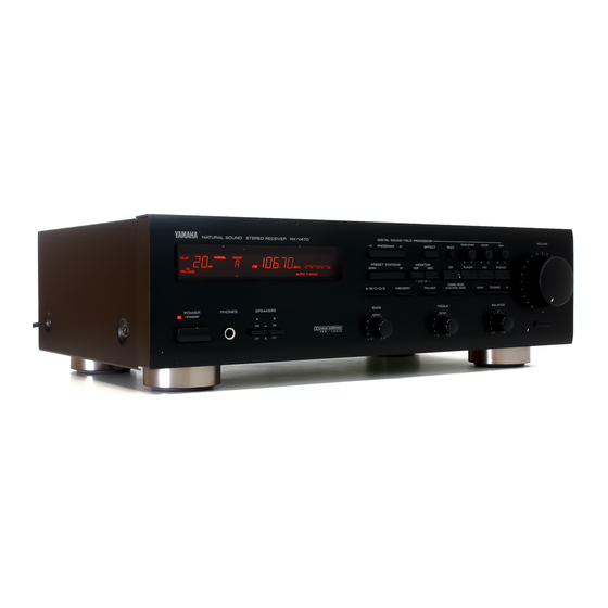
RX-V470
Natural Sound Stereo Receiver
IMPORTANT!
Please record the serial number of this unit in the space
below.
Model:
Serial No.:
The serial number is located on the rear of the unit.
Retain this Owner's Manual in a safe place for future
reference.
WARNING
To reduce the risk of fire or electric shock, do not expose
this unit to rain or moisture.
OWNER'S MANUAL
1
Advertisement
Table of Contents

Related Manuals for Yamaha RX-V470


Summary of Contents for Yamaha RX-V470
-
Page 1: Natural Sound Stereo Receiver
The exclamation point within an equilateral triangle is intended to alert you to the presence of important operating and maintenance (servicing) instructions in the literature accompanying the appliance. RX-V470 Natural Sound Stereo Receiver IMPORTANT! Please record the serial number of this unit in the space below. -
Page 2: Safety Instructions
– and, most importantly, without affecting your sensitive hearing. Since hearing damage from loud sounds is often undetectable until it is too late, YAMAHA and the Electronic Industries Association's Consumer Electronics Group recommend you avoid prolonged exposure to excessive volume levels. -
Page 3: Caution
This product, when installed as indicated in the instructions contained in this manual, meets FCC requirements. Modifications not expressly approved by Yamaha may void your authority, granted by the FCC, to use the product. IMPORTANT: When connecting this product to accessories and/or another product use only high quality shielded cables. -
Page 4: Table Of Contents
Thank you for selecting this YAMAHA stereo receiver. SUPPLIED ACCESSORIES After unpacking, check that the following parts are contained. ÷ Indoor FM Antenna ÷ Remote Control Transmitter ÷ Batteries (size AA, R6, UM-3) Caution ...3 Supplied Accessories ...4 Features ...4 Profile of This Unit ...5... -
Page 5: Profile Of This Unit
You are the proud owner of a Yamaha RX-V470 stereo receiver –an extremely sophisticated audio component. The Digital Sound Field Processor (DSP) built into this unit takes full advantage of Yamaha’s undisputed leadership in the field of digital audio processing to bring you a whole new world of listening experiences. Follow the instructions in this manual carefully when setting up your system, and this unit will sonically transform your room into a wide range of listening environments –movie... -
Page 6: Speaker Setting Up For This Unit
SPEAKER SETTING UP FOR THIS UNIT SPEAKERS TO BE USED This unit is designed to provide the best sound-field quality with a 5 speaker configuration. The speakers to be used with this unit will be mainly front speakers, rear speakers, and a center speaker. -
Page 7: Connections
Before attempting to make any connections to or from this unit, be sure to first switch OFF the power to this unit and to any other components to which connections are being made. CONNECTIONS WITH OTHER COMPONENTS When making connections between this unit and other components, be sure all connections are made correctly, that is to say L (left) to L, R (right) to R, “+”... -
Page 8: Connecting Speakers
CONNECTING SPEAKERS Front speakers A Right Rear speakers Right Left SPEAKERS CENTER REAR REAR – – SPEAKERS FRONT – – TAPE TAPE PB REC OUT TAPE PB REC OUT AUDIO SIGNAL Center speaker Right Left Front speakers B Connect the SPEAKERS terminals to your speakers with wire of the proper gauge, cut to be as short as possible. -
Page 9: Antenna Connections
ANTENNA CONNECTIONS ÷ Each antenna should be connected to the designated terminals correctly, referring to the following figure. ÷ Both AM and FM indoor antennas are included with this unit. In general, these antennas will probably provide sufficient signal strength. Nevertheless, a properly installed outdoor antenna will give clearer reception than an indoor one. If you experience poor reception quality, an outdoor antenna may result in improvement. -
Page 10: Adjustment Before Operation
ADJUSTMENT BEFORE OPERATION Speaker balance adjustment This procedure lets you adjust the sound output level balance between the front, center, and rear speakers using the built-in test tone generator. With this adjustment, the sound output level heard at the listening position will be the same from each speaker. - Page 11 Press the TEST button. TEST TEST Blinks. The TEST indicator continues blinking until the TEST button is pressed again to complete the adjustment. Turn up the volume. VOLUME –dB You will hear a test tone (like pink noise) from the left front speaker, then the center speaker, then the right front speaker, and then the rear speakers, for about two seconds each.
- Page 12 Make the sound output level of the center speaker the same as that of the front speakers with the CENTER level control. (When you selected the PHANTOM mode in step 7, skip this step.) CENTER TEST Adjust while the C indicator is llit. Make the sound output level of the rear speakers the same as that of the front speakers with the REAR level control.
-
Page 13: Playing A Source
Set the VOLUME control to the “ ” position. VOLUME –dB Turn on the power. POWER Select the desired input source. (For video sources, turn the TV/monitor ON.) MONITOR TUNER VCR TAPE The corresponding indicator lights on the display. (When TUNER is selected, the previously received frequency appears on the display.) Select the front speakers to be used. -
Page 14: Recording A Source
Select the source to be recorded. MONITOR TUNER VCR TAPE COPY ÷ To dub from tape to tape, you should record from the component connected to the VCR jacks to the component connected to the TAPE jacks. ÷ When selecting LD, TUNER, CD or PHONO, make sure that the TAPE MONITOR and VCR MONITOR input selectors are not selected. -
Page 15: Adjusting The Balance And Tone
ADJUSTING THE BALANCE AND TONE PHONES To adjust the BALANCE control Adjust the balance of the output volume to the left and right speakers to compensate for sound imbalance caused by speaker location or listening room conditions. BALANCE Note These controls are effective only for the sound from the front speakers. -
Page 16: Tuning Operations
Normally, if station signals are strong and there is no interference, quick automatic-search tuning (AUTOMATIC TUNING) is possible. However, if signals of the station you want to select are weak, you must tune to it manually (MANUAL TUNING). AUTOMATIC TUNING Press the TUNER button and select the reception band (FM or AM) by pressing the FM/AM button. -
Page 17: Preset Tuning
PRESET TUNING This unit can store station frequencies (selected by tuning operation) by using preset station buttons. With this function, you can select any desired station simply by specifying the corresponding preset station number. Up to 40 stations (8 stations per page) can be stored. -
Page 18: Using Digital Sound Field Processor (Dsp)
USING DIGITAL SOUND FIELD PROCESSOR (DSP) This unit incorporates a sophisticated, multi-program digital sound field processor, which allows you to expand and shape the audio sound field from both the audio and video sources, for a theater-like experience in the listening/viewing room. This digital sound field processor has 6 programs, including 2 programs for the Dolby Pro Logic Surround sound system (Ÿ... - Page 19 Description of Each Sound Field Program PROGRAM ŸPRO LOGIC This program is effective for playback of sources encoded with the Dolby Surround. The employment of the digital signal processing system improves crosstalk and transfers the sound source more smoothly and precisely, compared to the conventional type. A stable movie sound field is recreated.
- Page 20 To play a source with the digital sound field processor ŸPRO LOGIC–ENHANCED CNCT VIDEO CENTER MODE ŸSURROUND MONO MOVIE ROCK DELAY – VOLUME TIME EFFECT – Play a source. (Follow steps 1, 2, 3, 4, 5, and 6 shown in “PLAYING A SOURCE”...
- Page 21 Adjustment of the front effect level (Except for ŸPRO LOGIC) If desired, you can adjust the effect sound output level of the front speakers with the FRONT EFFECT level control. FRONT EFFECT ÷ If any DSP program is not used, the FRONT EFFECT level control does not function.
-
Page 22: Setting The Sleep Timer
If you use the SLEEP timer of this unit, you can set this unit to be turned off automatically. When you are going to sleep while enjoying a broadcast or other desired input source, this timer function is helpful. Notes ÷... -
Page 23: Remote Control Transmitter
The remote control transmitter provided with this unit is designed to control all the most commonly used functions of the unit. If the CD player and tape deck connected to this unit are YAMAHA components designed for remote control compatibility, then this remote control transmitter will also control various functions of each component. -
Page 24: Notes About The Remote Control Transmitter
NOTES ABOUT THE REMOTE CONTROL TRANSMITTER Battery installation Press the lid's locking tab down and, at the same time, pull out the battery compartment lid in the direction of the arrow. Install the batteries (size AA, R6, UM-3) with correct polarities. -
Page 25: Troubleshooting
If the unit fails to operate normally, check the following points to determine whether the fault can be corrected by the simple measures suggested. If it cannot be corrected, or if the fault is not listed in the SYMPTOM column, disconnect the power cord and contact your authorized YAMAHA dealer or service center for help. SYMPTOM The unit fails to turn on when the POWER switch is pressed. -
Page 26: Specifications
AUDIO SECTION Minimum RMS Output Power per Channel Front L,R 8 ohms, 20 Hz to 20 kHz, 0.04% THD ... 50W+50W 6 ohms, 20 Hz to 20 kHz, 0.06% THD [U.S.A. and Canada models] ... 55W+55W Center 8 ohms, 1 kHz, 0.5% THD ... 50W Rear L, R 8 ohms, 1 kHz, 0.5% THD ... - Page 27 YAMAHA ELECTRONIK EUROPA G.m.b.H. SIEMENSSTR, 22-34, D-2084 RELLINGEN, BEI HAMBURG, F.R. OF GERMANY YAMAHA ELECTRONIQUE FRANCE S.A. 17 RUE DES CAMPANULES, LOGNES 77321 MARNE LA VALLEE CEDEX 2 FRANCE YAMAHA ELECTRONICS (UK) LTD. YAMAHA HOUSE, 200 RICKMANSWORTH ROAD WATFORD, HERTS WD1 7JS, ENGLAND YAMAHA SCANDINAVIA A.B.