
Related Manuals for Yamaha HTR-5250


Summary of Contents for Yamaha HTR-5250
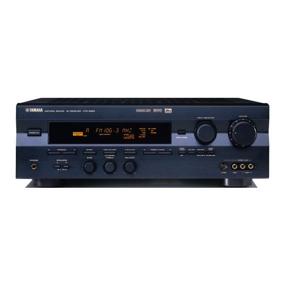
- Page 1 U C A HTR-5250 Natural Sound AV Receiver Ampli-tuner audio-vidéo OWNER’S MANUAL MODE D’EMPLOI...
-
Page 2: Safety Instructions
CAUTION RISK OF ELECTRIC SHOCK DO NOT OPEN CAUTION: TO REDUCE THE RISK OF ELECTRIC SHOCK, DO NOT REMOVE COVER (OR BACK). NO USER-SERVICEABLE PARTS INSIDE. REFER SERVICING TO QUALIFIED SERVICE PERSONNEL. • Explanation of Graphical Symbols The lightning flash with arrowhead symbol, within an equilateral triangle, is intended to alert you to the presence of uninsulated “dangerous voltage”... - Page 3 This product, when installed as indicated in the instructions contained in this manual, meets FCC requirements. Modifications not expressly approved by Yamaha may void your authority, granted by the FCC, to use the product. 2. IMPORTANT : When connecting this product to accessories and/or another product use only high quality shielded cables.
- Page 4 Using this unit with a higher voltage than specified is dangerous and may result in fire or other accidents. YAMAHA will not be held responsible for any damage resulting from the use of this unit with a voltage other than that specified.
-
Page 5: Table Of Contents
Processing Digital Sound Field Processor (DSP) Dolby Pro Logic Decoder Dolby Digital Decoder DTS Decoder CINEMA DSP: Combination of YAMAHA DSP Technology and Dolby Pro Logic, Dolby Digital or Sophisticated FM/AM Tuner 40-Station Random Access Preset Tuning Automatic Preset Tuning... -
Page 6: Getting Started
Checking the Package Contents Check that the following items are included in your package. Remote control Battery Installation in the Remote Control Turn the remote control over and slide the battery compartment cover in the direction of the arrow. Insert the batteries (AAA, R03 or UM-4 type) according the polarity markings on the inside of the battery compartment. - Page 7 Using the Remote Control Remote control sensor Within approximately 6 m (20 feet) The remote control transmits a directional infrared beam. Be sure to aim the remote control directly at the infrared sensor during operation. When the sensor is covered or there is a large object between the remote control and the sensor, the sensor cannot receive signals.
-
Page 8: Controls And Functions
Front Panel – STANDBY/ON Press this switch to turn on the power of this unit or to set this unit in the standby mode. Before turning the power on, set VOLUME to the “m” position. Standby mode In this mode, this unit consumes a very small quantity of power to receive infrared-signals from the remote control. - Page 9 Tone controls These controls are only effective for the sound from the main speakers. a) BASS Turn this control clockwise to increase or counterclockwise to decrease the low-frequency response. The “0” position produces a flat response. b) TREBLE Turn this control clockwise to increase or counterclockwise to decrease the high-frequency response.
- Page 10 CONTROLS AND FUNCTIONS Display t indicator The “t” indicator lights up when the built-in DTS decoder is on. DSP program indicators The name of the selected DSP program lights up in the following cases: • When the tuner is selected as the input source. •...
- Page 11 Remote Control This section describes the basic operation of this unit with the remote control. First, set the selector dial to the AMP/ TUN position. Refer to “PRESET REMOTE CONTROL” on page 42 for full details. TV POWER TV VOLUME Press this button to switch the function of the numeric buttons to the DSP program selector.
-
Page 12: Description Of The Numeric Buttons
CONTROLS AND FUNCTIONS A/B/C/D/E, PRESET +/– These buttons are used to select a preset station. A/B/C/D/E: To select one of a group (A to E) of preset stations PRESET +/–: To select a preset station number (1 to 8) d (next), u (back) These buttons are used to advance or go back one selection on the SET MENU and TIME/LEVEL mode. -
Page 13: Preparation
LFE (low frequency effect) channel with high fidelity when playing back a source encoded with Dolby Digital or DTS. The YAMAHA Active Servo Processing Subwoofer System is ideal for natural and lively bass reproduction. -
Page 14: Connections
When you connect other YAMAHA audio components (such as a tape deck, MD recorder and CD player or changer), connect it to the terminals with the same number labels as !, #, $ etc. YAMAHA applies this labeling system to all its products. -
Page 15: Indoor/Outdoor Fm Antenna
Connecting the Antennas Both AM and FM indoor antennas are included with this unit. In general, these antennas should provide sufficient signal strength. However, a properly installed outdoor antenna provides clearer reception than an indoor one. If you experience poor reception quality, an outdoor antenna may improve the quality. -
Page 16: Connecting The Am Loop Antenna
CONNECTIONS AM loop antenna (included) AM loop antenna Connecting the AM loop antenna Antenna stand Outdoor AM antenna Vinyl covered wire (5 m to 10 m) Ground (GND terminal) The AM loop antenna can be removed from the stand and attached to a wall, etc. -
Page 17: Connecting An Audio Component
Connecting an Audio Component Turntable OUTPUT OUTPUT CD player Be sure to connect the right channel (R), left channel (L), input (IN) and output (OUT) properly. (U.S.A. model) LINE OUT LINE IN Tape deck or MD recorder PHONO terminals These terminals are used to connect a turntable with an MM or high-output MC cartridge. - Page 18 CONNECTIONS Connecting a Video Component TV monitor DVD/LD player S VIDEO ANALOG AUDIO OUT (U.S.A. model) S VIDEO ANALOG AUDIO OUT Audio signal terminals Be sure to connect the right channel (R), left channel (L), input (IN) and output (OUT) properly. S Video signal terminals Use a special S VIDEO cable (commercially available) for the S VIDEO connection.
- Page 19 VIDEO terminals (composite) DVD/LD player Cable TV/satellite tuner VIDEO OUT VIDEO VIDEO TV monitor TV/digital TV Video signal Signal flow VIDEO AUX terminals (on the front panel) AUDIO OUT R AUDIO OUT L VIDEO OUT S VIDEO OUT Connecting to an External Decoder External decoder SURROUND MAIN...
-
Page 20: Connecting The Speakers
Connecting the Speakers Right Subwoofer connection When using a subwoofer with built- in amplifier, including the YAMAHA Active Servo Processing Subwoofer System, connect the input terminal of the subwoofer system to the SUBWOOFER OUTPUT terminal of this unit. Low bass signals distributed from... -
Page 21: Connecting To An External Amplifier
Speaker cables 10 mm (3/8”) Connecting to the MAIN SPEAKERS terminals Red: positive (+) Black: negative (–) Connecting to the REAR and CENTER SPEAKERS terminals Red: positive (+) Black: negative (–) Connecting to an external amplifier The speaker connections described on page 16 are fine for most applications. If you wish to drive your existing amplifier, the following terminals are available for connecting an external amplifier(s) to this unit. -
Page 22: Impedance Selector Switch
CONNECTIONS IMPEDANCE SELECTOR Switch WARNING Do not change the IMPEDANCE SELECTOR switch setting while the power of this unit is on, otherwise the unit may be damaged. If this unit fails to turn on when STANDBY/ON (or POWER) is pressed, the IMPEDANCE SELECTOR switch may not be fully slide to either position. -
Page 23: Adjusting The Speaker Balance
ADJUSTING THE SPEAKER BALANCE This procedure lets you adjust the sound output level balance between the main, center and rear speakers by using the built-in test tone generator. When this adjustment is performed, the sound output level heard at the listening position will be the same from each speaker. -
Page 24: Adjusting The Speaker Balance
ADJUSTING THE SPEAKER BALANCE Adjust BALANCE on the front panel so that the sound output level of the right main speaker and the left main speaker is the same. Press TIME/LEVEL repeatedly to select the speaker to be adjusted. “CENTER”, “R SUR.” or “L SUR.”... -
Page 25: Basic Operation
BASIC OPERATION When using the remote control, set the selector dial to the AMP/TUN position. – – Set VOLUME to the “m” position. Turn the power on. Front panel Press SPEAKERS A or B to select the main speakers to be used. If you use two main speaker systems, press both A and B. -
Page 26: Playing A Source
PLAYING A SOURCE Play the source. Refer to the instructions for the source component (and page 27 for details about tuning). Note • When controlling an audio/video component (tape deck, MD recorder, CD player, DVD/LD player, etc.) with the remote control, set the selector dial to the appropriate position (TAPE/ MD, CD, DVD/LD, etc.), corresponding to the component you want to control. - Page 27 Input Mode (for the DVD/LD, TV/ digital TV and cable TV/satellite tuner sources) This unit allows you to switch the input mode for sources that send both digital and analog signals to this unit. The AUTO, DTS and ANALOG input modes are provided. When you turn on the power of this unit, the input mode for the DVD/LD source is always set to AUTO and for TV/ digital TV or cable TV/satellite tuner source is set according...
- Page 28 PLAYING A SOURCE Notes on playing a source encoded with DTS • If “DATA ERROR” appears on the display while playing an LD source encoded with DTS, stop playback and turn the player off and then on again. • If the digital output data of the player has been processed in any way, you may not be able to perform DTS decoding even if you make a digital connection between this unit and the player.
-
Page 29: Digital Sound Field Processor (Dsp) Effect
DIGITAL SOUND FIELD PROCESSOR (DSP) EFFECT Selecting a DSP Program You can enhance your listening experience by selecting a DSP program. Refer to pages 32 to 34 for details about each program. – – On the front panel Make sure that the effect speakers (center and rear) and subwoofer are turned on. - Page 30 DIGITAL SOUND FIELD PROCESSOR (DSP) EFFECT Canceling the Sound Effect (turning off the effect speakers) Press EFFECT to cancel the sound effect and monitor only the main sound. Press EFFECT again to turn the sound effect back on. If the selector dial is set to a position other than the DSP/TUN position, first press DSP and then EFFECT on the remote control.
-
Page 31: Tuning
Automatic tuning is effective when station signals are strong and there is no interference. However, if the signal from the station you want to select is weak, you must tune in to it manually (manual tuning). – – Automatic Tuning Use INPUT SELECTOR to select the tuner as the input source. - Page 32 TUNING Automatic Preset Tuning (for FM stations only) You can make use of the automatic preset tuning function for FM stations only. This function enables the unit to automatically tune in with strong signals and to sequentially store up to 40 FM stations (5 groups x 8 stations). –...
-
Page 33: Manual Preset Tuning
Manual Preset Tuning You can also store up to 40 stations (5 groups x 8 stations) manually. – – Tune in to the desired station. Refer to page 27 for the tuning procedure. Press MEMORY. The “MEMORY” indicator flashes for about five seconds. -
Page 34: Exchanging Preset Stations
TUNING Exchanging Preset Stations You can exchange the assignment of two preset stations with each other. Example: If you want to exchange preset station “E1” with “A5” – – Recall preset station “E1”. Refer to the procedure in the section “To Recall a Preset Station”... -
Page 35: Recording A Source On Tape, Md Or Video Cassette
RECORDING A SOURCE ON TAPE, MD OR VIDEO CASSETTE Recording adjustments and other operations are performed from the tape deck, MD recorder or VCR. Refer to the instructions for these components. – – Set VOLUME to the “m” position. Select the source you want to record. Front panel Begin recording by the tape deck, MD recorder or VCR connected to this unit. -
Page 36: Advanced Operation
ADVANCED OPERATION This unit incorporates a sophisticated, multi-program digital sound field processor (DSP). This processor allows you to electronically expand and change the shape of the audio sound field from both audio and video sources, creating a theater- like experience in your listening room. You can create outstanding audio sound by selecting a suitable DSP program (this will, of course, depend on what you are listening to). - Page 37 PROGRAM MOVIE [1] 70 mm SPECTACLE THEATER 1 ( o x ) • Input source: • Output channel: • DSP: [2] DGTL SPECTACLE ( g x ) • Input source: • Output channel: • DSP: [3] DTS SPECTACLE ( t x ) •...
- Page 38 SOUND FIELD PROGRAM PROGRAM MONO MOVIE ( x ) • Input source: Monaural • Output channel: 1 channel • DSP: TV SPORTS ( x ) • Input source: Audio/Video • Output channel: 2 to 5.1 channels • DSP: 2 to 3 (presence & surround) For Hi-Fi audio sources PROGRAM DISCO ( x )
-
Page 39: Set Menu
This unit provides you with the following items on the SET MENU to maximize the performance of your system and expand your enjoyment for audio listening and video watching. 1. CENTER SP 2. REAR SP 3. MAIN SP 4. BASS OUT 5. -
Page 40: Set Menu
SET MENU Description of Each Item 1. CENTER SP Choices: LRG (Large)/SML (Small)/NONE Preset position: LRG (Large) LRG (Large) Select this position if your center speaker is approximately the same size as the main speakers. In this position, full- range signals on the center channel are directed to the center speaker. - Page 41 5. MAIN LVL Choices: NORM (Normal)/–10 dB Preset position: NORM (Normal) NORM (Normal) Normally select this position. –10 dB Select this position if the sound output from the main speakers is too loud and cannot be balanced with the sound output from the center and rear speakers.
- Page 42 SET MENU 8. DTS LFE (Adjusting the output level of the LFE channel for DTS) Control range: –10 dB to +10 dB (in 1 dB steps) Preset value: 0 dB Note • This adjustment is effective only when DTS is being decoded and the selected source encoded with DTS contains LFE signals.
-
Page 43: Delay Time And Speaker Output Levels
DELAY TIME AND SPEAKER OUTPUT LEVELS When using the digital sound field processor with the Dolby Pro Logic decoder, Dolby Digital decoder or DTS decoder, you can adjust the delay time between the main sound and sound effect, and each speaker’s output level as you wish. Note •... -
Page 44: Delay Time And Speaker Output Levels
DELAY TIME AND SPEAKER OUTPUT LEVELS Adjusting Method Adjustments should be performed with the remote control while watching the information on the display. Set the selector dial to the AMP/TUN (or DSP/TUN) position. Press TIME/LEVEL repeatedly to select the item you want to adjust. Each time you press TIME/LEVEL, the selected item changes and appears on the display as shown below. -
Page 45: Sleep Timer
The SLEEP timer can be used to automatically set this unit in the standby mode. This timer is useful when you are going to sleep while enjoying the desired input source. The SLEEP timer can only be set with the remote control. Note •... -
Page 46: Preset Remote Control
The provided remote control is factory set to control not only this unit but also most YAMAHA audio components connected to it. Selector Dial There are nine positions that you can select to control connected components with this remote control. For example, if the CD position is selected, the remote control is set in the CD operation mode, allowing the CD player to be operated by the buttons on the remote control. - Page 47 Controlling the Components Connected to This Unit Example: To control a YAMAHA CD player Make sure that VOLUME is set to the “m” position. Set the selector dial to the CD position. Turn on the power. Press INPUT. The indicator lights up for about three second.
- Page 48 PRESET REMOTE CONTROL Description of Each Position TAPE/MD position Select the TAPE/MD position. r REC/PAUSE This button gives a pause in recording on a tape deck or MD recorder. p PLAY This button plays a tape or an MD. b DIR A (TAPE) This button selects the playing direction of deck A.
- Page 49 (center and rear). DISPLAY e PAUSE This button gives a pause in operation. The button functions as PAUSE/STOP* for operating a YAMAHA CD player under factory setting. a SKIP+ This button skips to the beginning of the next track.
- Page 50 MENU DOWN MENU AV POWER This button turns on the YAMAHA DVD player if you have set the code number “0048”. Also this button turns on the DVD player that has a remote control with a power button if you have set the code for another manufacturer.
- Page 51 VCR position Select the VCR position. Numeric buttons VCR REC Press this button twice to start ENTER/RECALL recording. CHANNEL +/– DISPLAY PAUSE PLAY STOP REWIND FAST FORWARD AV POWER This button turns on a VCR that has a remote control with a power button if you have set the code for your VCR.
-
Page 52: Setup Codes
PRESET REMOTE CONTROL Advanced Information Setup codes You can set the code for the manufacturer of your component in each position of the selector dial. Turn on your component to be used. Set the selector dial to the desired position for the component (TAPE/MD, CD, DVD/LD, etc.). - Page 53 The following codes are factory set. Selector dial Code Component position 0101 CBL/SAT Satellite tuner 0006 0002 DVD/LD DVD player 0008 (YAMAHA DVD player) CD player 0005 (YAMAHA CD player) TAPE/MD Tape deck 0004 (YAMAHA Tape deck) AMP/TUN this unit 0003 DSP/TUN this unit...
-
Page 54: Appendix
If the unit fails to operate normally, check the following points to determine whether the fault can be corrected by the simple measures suggested. If it cannot be corrected, or if the fault is not listed in the SYMPTOM column, disconnect the power cord and contact your authorized YAMAHA dealer or service center. General... -
Page 55: Troubleshooting
SYMPTOM No sound from the The sound output level of the center speaker is center speaker. set to minimum. “CENTER SP” on the SET MENU is set to the NONE position. Incorrect DSP program is selected. The source encoded with Dolby Digital or DTS does not have a center channel signal. - Page 56 TROUBLESHOOTING Tuner SYMPTOM FM stereo reception The characteristics of FM stereo broadcasts is noisy. may cause this problem when the transmitter is too far away or the antenna input is poor. There is distortion, There is multipath interference. and clear reception cannot be obtained even with a good FM antenna.
- Page 57 When playing back a source encoded with DTS SYMPTOM A loud hissing noise is The player which plays back the source is not heard when playing back connected to a digital audio signal input a source encoded with terminal of this unit. DTS.
-
Page 58: Specifications
AUDIO SECTION • Minimum RMS Output Power 20 Hz to 20 kHz, 0.06% THD, 8 ohms Main L/R, Center, Rear L/R ... 100 W*/70 W 1 kHz, 0.09% THD, 8 ohms Main L/R, Center, Rear L/R ... 110 W*/80 W •... -
Page 59: Glossary
Dolby Surround, Dolby Digital or DTS Digital Surround sounds. The YAMAHA “CINEMA DSP” logo indicates those programs that are created by the combination of YAMAHA DSP technology and Dolby Surround, Dolby Digital or DTS. LFE 0.1 Channel This channel is for reproduction of low bass signals. -
Page 60: Index
Accessories ... 2 AC outlet ... 18 Antennas ... 11, 12 BALANCE ... 22 BGV (background video) function ... 22 Canceling sound effect ... 26 CINEMA DSP ... 34, 55 Connections Antennas ... 11, 12 Audio components (tape deck/MD recorder, CD player and turntable) ... - Page 61 LIST OF MANUFACTURER’S CODES LISTES DES CODES FABRICANT ELECTRON ELIN A-MARK 1161 ELTA A TANDY 0941 EMERSON ABEX 1151 ADMIRA 1141 ADVENTURA 1131 AIKO 1121 AIWA 1481 AKAI 0331, 1101, 1111 ALBA 0431 ALLERON 1091 ENVISION AMBASSADOR 1081 ERRES AMSTRAD 0481, 1081 ETRON ANAM...
- Page 62 0971, 0991, 1031, SCIENTIFIC ATLANTA 75 1091, 1111, 1771 WATSON 1001 SCIENTIFIC ATLANTA 8650 XOGEGO 1611, 1621, 1661, 1741, 1761 SIGNAL YAMAHA 0221, 0361, 0571, SL MARX 1031, 1111, 1141, SPECTAVISION 1381 STANDARD COMPONENTS YOKO 1001 ZENITH 0011, 0041, 0891,...
-
Page 63: Dvd Player
VIDEO CONCEPTS 0222, 0372, 0382, 0392, 0412, 0932 PENNY 0202, 0432, 0602, WARDS 0632, 0692, 0912, 0922, 0932 PENTAX 0592, 0602 PERDIO 0992 YAMAHA PHILCO 0002, 0932 ZENITH PHILIPS 0002, 0282, 0402, 0492, 0932 PILOT 0912 DVD PLAYER PIONEER 0442, 0542... - Page 64 YAMAHA ELECTRONIQUE FRANCE S.A. RUE AMBROISE CROIZAT BP70 CROISSY-BEAUBOURG 77312 MARNE-LA-VALLEE CEDEX02, FRANCE YAMAHA ELECTRONICS (UK) LTD. YAMAHA HOUSE, 200 RICKMANSWORTH ROAD WATFORD, HERTS WD1 7JS, ENGLAND YAMAHA SCANDINAVIA A.B. J A WETTERGRENS GATA 1, BOX 30053, 400 43 VÄSTRA FRÖLUNDA, SWEDEN Printed in Malaysia ID V471950-1 YAMAHA MUSIC AUSTRALIA PTY, LTD.
- Page 65 Quick Reference Card PRESET +/– TEST j (left), i (right) TIME/LEVEL TV POWER TV VOLUME program TV INPUT selector EFFECT TAPE/MD REC/PAUSE PLAY DIR A (TAPE) SKIP– (MD) REWIND (TAPE) SEARCH (MD) AMP/TUN INPUT Input selector buttons A/B/C/D/E d (next), u (back) SET MENU STANDBY POWER...
- Page 66 Quick Reference Card DVD/LD DISC SKIP+/– PLAY SKIP– SEARCH INPUT Numeric buttons ENTER/ CHANNEL RECALL +/– DISPLAY VCR REC PLAY PAUSE STOP FAST REWIND FORWARD AV POWER Press this button twice to start recording. Appuyer deux fois sur cette touche pour commencer l’enregistrement. Drücken Sie diese Taste zweimal, um die Aufnahme zu starten.
- Page 67 DVD player DIGITAL OUT AUDIO OUT VIDEO S VIDEO COAXIAL VIDEO S VIDEO COAXIAL DIGITAL OUT ANALOG AUDIO OUT VIDEO IN S VIDEO IN DSP-A5 only TV Monitor LD player DOLBY DOLBY DIGITAL DIGITAL OPTICAL RF OUT RF OUT OPTICAL DOLBY DIGITAL DIGITAL OUT RF IN...