Advertisement
Quick Links
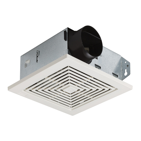
MODELS 670, 671, 671MX, 688 & 689
CEILING/WALL FANS
READ AND SAVE THESE
INSTRUCTIONS
WARNING
TO REDUCE THE RISK OF FIRE, ELECTRIC SHOCK, OR INJURY
TO PERSONS, OBSERVE THE FOLLOWING:
1. Use this unit only in the manner intended by the manufacturer.
If you have questions, contact the manufacturer at the address
or telephone number listed in the warranty.
2. Before servicing or cleaning unit, switch power off at service
panel and lock the service disconnecting means to prevent
power from being switched on accidentally. When the service
disconnecting means cannot be locked, securely fasten a
prominent warning device, such as a tag, to the service panel.
3. Installation work and electrical wiring must be done by a qualified
person(s) in accordance with all applicable codes and standards,
including fire-rated construction codes and standards.
4. Sufficient air is needed for proper combustion and exhausting
of gases through the flue (chimney) of fuel burning equip-
ment to prevent backdrafting. Follow the heating equipment
manufacturer's guideline and safety standards such as those
published by the National Fire Protection Association (NFPA),
and the American Society for Heating, Refrigeration and Air
Conditioning Engineers (ASHRAE), and the local code authori-
ties.
5. When cutting or drilling into wall or ceiling, do not damage
electrical wiring and other hidden utilities.
6. Ducted fans must always be vented to the outdoors.
7. Acceptable for use over a bathtub or shower when installed in
a GFCI protected branch circuit.
8. Install fan at least five feet (1.52 m) above the floor.
9. Never place a switch where it can be reached from a tub or
shower.
10. This unit must be grounded.
CAUTION
1. For general ventilating use only. Do not use to exhaust hazardous or explosive materials
and vapors.
2. To avoid motor bearing damage and noisy and/or unbalanced impellers, keep drywall
spray, construction dust, etc. off power unit.
3. Please read specification label on product for further information and requirements.
USE AND CARE
DISCONNECT ELECTRIC POWER SUPPLY AND LOCK OUT SERVICE PANEL BEFORE
SERVICING THE UNIT.
PREVENTATIVE MAINTENANCE
A clean fan provides better service. Disconnect the power supply and clean the fan as
described below:
TO CLEAN GRILLE - Use a mild detergent, such as dishwashing ligquid, and dry with a soft
cloth. DO NOT USE ABRASIVE CLOTHS, STEEL WOOL PADS, OR SCOURING POWDERS.
TO CLEAN FAN ASSEMBLY - Unplug motor cord from receptacle. To remove motor plate:
Find the single tab on the motor plate (located next to the receptacle). Push up near motor
plate tab while pushing out on side of housing. Or insert a straight-blade screwdriver into
slot in housing (next to tab) and twist screwdriver. Gently vacuum fan, motor and interior
of housing. METAL AND ELECTRICAL PARTS SHOULD NEVER BE IMMERSED IN WATER.
TO REASSEMBLE ALL ABOVE PARTS - Reverse all procedures explained above.
MAINTENANCE
The motor is permanently lubricated and never needs oiling. If the motor bearings are making
excessive or unusual noises, replace the motor with the exact service motor. You should
replace the impeller at the same time.
INSTALLATION
1. Remove motor plate from housing by pushing down on rib in plate while pulling out on
side of housing. Motor plate may also be removed by inserting a straight-blade screw
driver into slot in housing and twisting screw driver. (FIG. 1)
2. Remove wiring cover from housing by pulling straight out. Unit is shipped ready to wire
through the top of housing. To wire through the side, bend housing flap to cover top hole
and expose side hole. DO NOT BREAK OFF FLAP. If flap breaks, Plug unused hole using
standard electrical hole plug. (FIG. 2)
3. Turn off electrical power at service entrance and connect power cable to housing using
appropriate connector. Wire black to black, white to white, and green to green or bare wire.
Push all wiring up into corner of unit and replace wiring cover. Make sure cover holds
housing flap in place against side or top of housing.
CAUTION: DO NOT ALLOW WIRES TO EXTEND OUTSIDE OF WIRING BOX. Wire left
exposed will become pinched or cut when motor plate is installed. Electrical shock
may result. (FIG. 3)
4. Choose the location for your fan. For best performance, use the shortest possible duct
run and a minimum number of elbows, For wall installations: Position unit so damper
flap closes when unit is off.
FIG. 1
SCREWDRIVER
SLOT
FIG. 2
WIRING
COVER
HOUSING
FLAP
FIG. 3
RECEPTACLE
SWITCH BOX
WHITE TO
WHITE
BLACK
SWITCH OR TIMER
WHITE TO
WHITE
GROUND
BLACK
120 VAC LINE IN
GREEN TO
GREEN OR
BARE WIRE
BLACK TO
BLACK
Advertisement

Related Manuals for Broan 670


Summary of Contents for Broan 670
- Page 1 MODELS 670, 671, 671MX, 688 & 689 CEILING/WALL FANS READ AND SAVE THESE INSTRUCTIONS FIG. 1 WARNING TO REDUCE THE RISK OF FIRE, ELECTRIC SHOCK, OR INJURY SCREWDRIVER TO PERSONS, OBSERVE THE FOLLOWING: SLOT 1. Use this unit only in the manner intended by the manufacturer.
- Page 2 Damper/Duct Connector S97015577 (Model 1667HMTL)) Receptacle S99271654 Wiring Cover S98006773 Screw, #8-18 S99150478 Always order replacement parts by "PART NUMBER" - not by "KEY NO." Looking for dependable home heating & cooling? Rely on Broan for quality and long-lasting products.