
Related Manuals for Emerson Tescom ER5K


Summary of Contents for Emerson Tescom ER5K
- Page 1 Automated Pressure Control Kits Product Manual 0-30,000 PSI Range Serving all of your pressure control needs... Instruction Manual DOPSM2095X012A September 2019 www.pressurecontrolsolutions.co.uk...
-
Page 3: Table Of Contents
ER5K Kits Table of Contents DOPSM2095X012 September 2019 Contents Section 1: Introduction ............1 Section 2: Before You Begin . -
Page 4: Section 1: Introduction
Section 1: Introduction ER5K Kits September 2019 DOPSM2095X012 Section 1: Introduction This manual is valid only for ER5K kits ER5K-XXXX. The instructions for individual components must also be read and followed and are either attached in the appendix or supplied separately. Section 2: Before You Begin WARNING This device is not intended for or rated for use in hazardous locations. - Page 5 ER5K Kits Section 2: Before You Begin DOPSM2095X012 September 2019 Possible consequence include but are not limited to: • High velocity fluid (gas or liquid) discharge • Electrocution • Parts ejected at high speed • Contact with fluids that may be hot, cold, toxic, or otherwise injurious •...
-
Page 6: Installation
Section 2: Before You Begin ER5K Kits September 2019 DOPSM2095X012 19. Read and follow precautions on compressed gas cylinder labels. 20. It is important that you analyze all aspects of your application and review all available information concerning the product or system. Obtain, read, and understand the Material Safety Data Sheet (MSDS) for each fluid used in your system. -
Page 7: Tescom Regulators
ER5K Kits Section 2: Before You Begin DOPSM2095X012 September 2019 REPAIR SERVICE If a controller leaks or malfunctions, take it out of service immediately. You must have instructions before doing any maintenance. Do not make any repairs you do not understand. Have qualified personnel make repairs. - Page 8 Section 2: Before You Begin ER5K Kits September 2019 DOPSM2095X012 CAUTION 1. Inspect the regulator, valve, and accessories before each use. 2. Never connect regulators, valves, or accessories to a supply source having a pressure greater than the maximum rated pressure of the regulator, valve, or accessory. 3.
- Page 9 ER5K Kits Section 2: Before You Begin DOPSM2095X012 September 2019 21. Many gases can cause suffocation. Make certain the area is well ventilated. Provide a device to warn employees of lack of Oxygen. 22. Never use oil or grease on these regulators, valves, or accessories. Oil and grease are easily ignited and may combine violently with some fluids under pressure.
-
Page 10: Section 3: Product Description
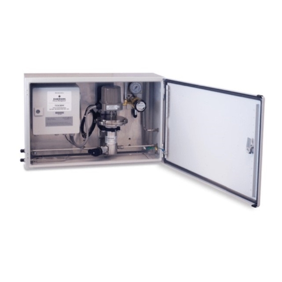
Section 3: Product Description ER5K Kits September 2019 DOPSM2095X012 Section 3: Product Description The ER5K Kits are designed to provide a complete pressure control system for the most common pressure reducing and back pressure control applications. All the components are completely assembled, professionally plumbed together and tested for proper operation to save the user time and the inconvenience of not having all the accessories and interconnections needed to get the system up and running. -
Page 15: Controlling System Pressure
ER5K Kits Section 3: Product Description DOPSM2095X012 September 2019 Connection ER5000 Supply Pressure 110 psig / 7.5 bar Adaptor External Regulator Transducer Outlet Pressure Inlet Pressure To Process Figure 3. Typical Pressure Reducing Application Controlling System Pressure In a typical application, the Outlet Port of the ER5000 connects to the top of a Dome Loaded or Air Actuated pressure reducing Regulator, usually through the included 1/2”... - Page 16 Section 3: Product Description ER5K Kits September 2019 DOPSM2095X012 USB Connection Inlet Exhaust Valve Valve ER5000 ER5000 Inlet Port Exhaust Port Supply Pressure Vents Pressure to Atmosphere 110 psig / Setpoint 7.5 bar Source can be either a ER5000 Outlet Port digital signal provided over and Adaptor USB or RS485, an analog...
-
Page 17: Section 4: Technical Data
ER5K Kits Section 4: Technical Data DOPSM2095X012 September 2019 Section 4: Technical Data Table 3. ER5K Pressure Reducing and Back Pressure Regulators Technical Data Dash Regulator Transducer Max. Regulator Flow Body Temperature Venting Weight Code Series pressure Input Pressure Coefficient Material approx. -
Page 18: Section 5: Installation
Section 5: Installation ER5K Kits September 2019 DOPSM2095X012 Section 5: Installation WARNING Do not attempt to select, install, use or maintain this regulator, valve or accessory until you have read and fully understand these instructions. Be sure this information reaches the operator and stays with the product after installation. - Page 19 ER5K Kits Section 5: Installation DOPSM2095X012 September 2019 Kits are mounted using 4 bolting locations in each corner MOUNTING SURFACE BOLT LOCATIONS BOLT LOCATIONS Note: Mounting hardware not included. 7.112 mm 0.28 in. 4x MOUNTING LOCATIONS 4x MOUNTING LOCATIONS 14.224 mm 0.56 in.
- Page 20 Section 5: Installation ER5K Kits September 2019 DOPSM2095X012 Attach up to 3500 psig / 241 bar clean, dry inert gas to the ER Supply Regulator Inlet port. Pressure supplied by the ER Supply Regulator to the ER5000 Inlet Port should not exceed 120 psig / 8.3 bar.
-
Page 21: System Leak Check
ER5K Kits Section 6: Wiring DOPSM2095X012 September 2019 System Leak Check After installation of all components and wiring: • Switch on the ER5000’s power supply. • Slowly apply ER supply pressure and then process pressure. Set the output pressure to a safe value. - Page 22 Section 6: Wiring ER5K Kits September 2019 DOPSM2095X012 Junction Box Wiring Table 4. Prewired Power Connections Junction Box Terminal Wire ER5000/Transducer Function 114A - braided (transducer) power ground from transducer 100C - red (transducer) +24V DC power to transducer 100C - violet +24V DC power to ER5000 101A - gray 24V return (power ground) from ER5000...
-
Page 23: Section 7: Maintenance
ER5K Kits Section 7: Maintenance DOPSM2095X012 September 2019 Section 7: Maintenance The maintenance and repair of pressure equipment must only be performed by trained personnel. Since every application exists under different conditions, the user is responsible for establishing a maintenance program based on their unique situation. Until enough data is collected to set up a schedule, we recommend a 6 to 12 month check of the following, however more frequent inspection and/or maintenance may be necessary. -
Page 24: Section 8: Drawings
Section 8: Drawings ER5K Kits September 2019 DOPSM2095X012 Section 8: Drawings The drawings in this manual are for reference only. For most up to date drawings please contact your local TESCOM representative. Electrical Drawing Figure 10. Electrical Drawing Section 8: Drawings... - Page 25 ER5K Kits Section 8: Drawings DOPSM2095X012 September 2019 Figure 10. Electrical Drawing (continued) Section 8: Drawings...
-
Page 26: Er5K Kit Drawing
Section 8: Drawings ER5K Kits September 2019 DOPSM2095X012 ER5K Kit Drawing ER5K - E F T A Table 8d. DASH PORTING/FITTING SIZE FOR INLET AND OUTLET, TUBING SIZE Metric System Table 8a. Imperial System DASH KIT CATEGORY Parts Assembled on Plate Table 8c. - Page 27 ER5K Kits Section 8: Drawings DOPSM2095X012 September 2019 All dimensions are reference & nominal Metric [millimeter] equivalents are in brackets ER5000FI-1 PANEL JUNCTION BOX WIRING GAUGE REGULATOR FOR ER SUPPLY (44-5212-241V-003) RELIEF VALVE 14.0" [355.6] REGULATOR (Pressure Reducing or Back Pressure) 26-2000 Series shown TRANSDUCER 23.2"...
- Page 28 Section 8: Drawings ER5K Kits September 2019 DOPSM2095X012 All dimensions are reference & nominal Metric [millimeter] equivalents are in brackets ENCLOSURE ER5000FI-1 GAUGE WIRING JUNCTION BOX REGULATOR FOR ER SUPPLY (44-5212-241V-003) RELIEF VALVE 15.8" [401.5] REGULATOR (Pressure Reducing or Back Pressure) DK shown TRANSDUCER 25.92"...
-
Page 35: Regulator Drawings
ER5K Kits Section 8: Drawings DOPSM2095X012 September 2019 Regulator Drawings 8.3.1 Regulator Flow Booster Table 9. Pilot-Operated Diaphragm Style Regulator Dimensions INLET AND OUTLET PART PILOT WEIGHT, INSTALLATION DIMENSIONS OUTLET GAUGE NUMBER PORT SIZE PORT SIZE PORT SIZE 269-529-04 1/4 NPT Ø... -
Page 36: Pressure Reducing Regulator Dk Series
Section 8: Drawings ER5K Kits September 2019 DOPSM2095X012 8.3.2 Pressure Reducing Regulator DK Series Figure 14. DK Series Regulator Section 8: Drawings... -
Page 37: Pressure Reducing Regulator 26-2000 Series
ER5K Kits Section 8: Drawings DOPSM2095X012 September 2019 8.3.3 Pressure Reducing Regulator 26-2000 Series Figure 15. 26-200 Series Regulator Section 8: Drawings... -
Page 38: Hydraulic Back Pressure Regulator 54-2100 Series
Section 8: Drawings ER5K Kits September 2019 DOPSM2095X012 8.3.4 Hydraulic Back Pressure Regulator 54-2100 Series Figure 16. 54-2100 Series Regulator Section 8: Drawings... -
Page 39: Back Pressure Regulator 26-1700 Series
ER5K Kits Section 8: Drawings DOPSM2095X012 September 2019 8.3.5 Back Pressure Regulator 26-1700 Series Figure 17. 26-1700 Series Regulator Section 8: Drawings... -
Page 40: Control Air Regulator 44-5200 Series
Section 8: Drawings ER5K Kits September 2019 DOPSM2095X012 8.3.6 Control Air Regulator 44-5200 Series Figure 18. 44-5200 Series Regulator Section 8: Drawings... -
Page 41: Pressure Transducer
ER5K Kits Section 8: Drawings DOPSM2095X012 September 2019 Pressure Transducer Table 10. Transducer Pressure Ranges AVAILABLE PRESSURE RANGE D51656 (psig) (bar) 1500 3000 6000 10,000 Figure 19. Pressure Transducer Section 8: Drawings... - Page 42 Section 8: Drawings ER5K Kits September 2019 DOPSM2095X012 8.4.1 Transducer 615 Series (Imperial Versions) Figure 20. 615 Series Transducer Section 8: Drawings...
- Page 43 ER5K Kits Section 8: Drawings DOPSM2095X012 September 2019 8.4.2 Transducer D51656-NB-XXX (Metric Versions) Table 11. D51656-NB-XXX Technical Data Specifications Model S-10 Pressure ranges Over pressure safety Burst pressure Pressure ranges Over pressure safety 1500 Burst pressure 1000 1700 3000 Materials Wetted parts Model S-10 Stainless steel...
- Page 44 Section 8: Drawings ER5K Kits September 2019 DOPSM2095X012 8.4.3 Transducer D51656-NB-XXX (Europe Only) Dimensions Connection NB DIN 175301-803 A 1/4 NPT L-connector per “Nominal size for US standard tapered pipe thread NPT” 1.89 [48] 1.14 [20] 0.85 [21.5] 0.51 [13] 1/4 NPT 1.28 [32.5]...
- Page 45 ER5K Kits Notes DOPSM2095X012 September 2015 For Your Own Notes: Notes...
- Page 46 Your Contact... Pressure Control Solutions Ltd 01604 811 406 01604 810 669 16 Knights Close | Earls Barton | Northampton | NN6 0JD sales@pressurecontrolsolutions.co.uk For Further www.pressurecontrolsolutions.co.uk Information Company Registration No: 9853578 | VAT Registration No: 225 7572 96...