Table of Contents
Advertisement
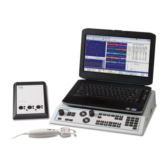
UltraPro S100
Natus Neurology Incorporated
UltraPro S100 User Guide
Part Number: 269-653300 Rev 05
© 2016 - 2018 Natus Medical Incorporated or one of its subsidiaries. All rights reserved.
Natus is a registered trademark of Natus Medical Incorporated. All product names appearing on this document are
trademarks or registered trademarks owned, licensed to, promoted or distributed by Natus Medical Incorporated,
its subsidiaries or affiliates. All other trademarks are the property of their respective owners.
September 13, 2018
Advertisement
Table of Contents

Related Manuals for natus UltraPro S100


Summary of Contents for natus UltraPro S100
- Page 1 © 2016 - 2018 Natus Medical Incorporated or one of its subsidiaries. All rights reserved. Natus is a registered trademark of Natus Medical Incorporated. All product names appearing on this document are trademarks or registered trademarks owned, licensed to, promoted or distributed by Natus Medical Incorporated,...
- Page 3 (Galvanic Skin Response and Sympathetic Skin Response). Autonomic testing also includes assessment of RR Interval variability. The UltraPro S100 is used to detect the physiologic function of the nervous system and to support the diagnosis of neuromuscular disease or condition.
-
Page 4: Ce Mark
UltraPro S100 Specification and accuracy information Please see the system Specification sheet 169-443700. Contact information Technical Support Natus Neurology Incorporated Domestic 3150 Pleasant View Road Middleton, WI USA 53562 Natus Neurology Incorporated 608-829-8500 3150 Pleasant View Road 1 800-356-0007 Middleton, WI USA 53562... -
Page 5: Labels And Symbols
Preface Labels and symbols The following labels and symbols may be affixed to the UltraPro S100 system: When applied on device: Attention: Consult Accompanying Doc- umentation (ISO 7000-0434A) When used in documentation: Caution, Warning or Precaution follows. Consult Operating Instructions. Failure to follow operating instruc- tions could place the patient or operator at risk (ISO 7010 M002). -
Page 6: Read The Safety Reference Guide
UltraPro S100 Read the safety reference guide Please read thoroughly the Additional Information and Safety Notes for Assorted Nicolet Brand Products Reference Guide included on a CD included with your system, paying special attention to the Safety information before applying power to and using your system. -
Page 7: Safety Summary
Preface Safety summary In this manual, two labels identify potentially dangerous or destructive conditions and procedures: The WARNING label identifies conditions or practices that may present danger to the patient and/or user. The CAUTION label identifies conditions or practices that could result in damage to the equipment. - Page 8 UltraPro S100 Table 1 describes the minimum size of the stimulus electrode needed to not exceed 0.25 W/cm to guard against the possibility of causing a burn due to excessive densities at the site of prolonged stimulation. Required Resistance Max Current...
-
Page 9: Maintenance
Preface Maintenance Inspecting the Routinely check the instrument for exterior damage. system Follow your medical facilities safety guidelines. Decontamination Decontamination that can be performed by the operator is limited to cleaning and disinfecting the device. Any maintenance inside the device must be performed by qualified service personnel only. -
Page 10: Preventative Maintenance
UltraPro S100 Preventative maintenance Safety checks The following safety checks should be conducted by qualified personnel only at least once a year and in the event of repair: Inspection for visible damage to device. 2. Inspection of mains cord and connecting cables. -
Page 11: Safety
The device must be disconnected from all voltage sources before being opened for any adjustment, replacement, maintenance or repair. • Service must be referred to Natus Neurology Incorporated authorized service personnel, except for such works described in this manual as being performed by the operator. -
Page 12: Recycling / Disposal
This includes batteries, printed circuit boards, electronic components, wiring and other elements of electronic devices. Follow all of your respective local laws and regulations for the proper disposal of batteries and any other parts of your system, such as monitors, UltraPro S100 amplifiers, keyboards, electrodes.-9... -
Page 13: Copyright
Natus Neurology Incorporated. The copyright and the foregoing restrictions on the copyright use extend to all media in which this information is preserved. -
Page 14: Software Copyright Protection
$100,000 in fines and 10 years in prison. Unless restricted by an agreement with Natus Neurology Incorporated, you are permitted to: a. Use this software on only one computer and by one user at a time. -
Page 15: Table Of Contents
Introduction 1-1 Technical description ............................1-3 Installation and servicing instructions ......................1-3 Device continuity maintenance and installation test- ...................1-3 UltraPro S100 amplifier and system essential performance ................1-4 Protective and equipment classifications ......................1-4 Intended operator...............................1-4 Using this guide ..............................1-5 About the system ..............................1-5 Ancillary accessories ............................1-6... - Page 16 UltraPro S100 System Overview 2-1 UltraPro S100 base unit .............................2-3 UltraPro S100 system interface.........................2-4 UltraPro S100 amplifier module - 3 and 4 channels ..................2-6 Current stimulator .............................2-8 Safety information- ............................2-8 Stimulus probe ..............................2-9 Changing polarity on the Comfort Probe RS10- ..................2-10 UltraPro S100 Base - Version #1 side panel....................2-11...
- Page 17 Table of Contents Performing an Exam 4-1 Setting up the system ............................4-3 Getting started-..............................4-3 Using UltraPro S100, Study Menu vs Test Menu- ..................4-4 Testing using Study menu- ...........................4-5 Testing using Test menu-..........................4-5 Patient to report in seven steps- ........................4-5 Example Motor Nerve Conduction Study......................4-6 About the waveform screen- .........................4-6...
- Page 18 UltraPro S100 Electromagnetic Compatibility (EMC) 6-1 List of UltraPro S100 items; additional and optional parts ................6-3 Table 1 - Electromagnetic emissions- ......................6-5 Table 4 - Immunity Test Levels - Enclosure Port-..................6-5 Table 5 – Immunity Test Levels – Input A.C. Power Port- ................6-6 Table 7 –...
- Page 19 Table of Contents Blank page. 13 September, 2018...
- Page 20 UltraPro S100 13 September, 2018...
-
Page 21: Introduction
Introduction September 13, 2018... - Page 22 UltraPro S100 Blank page. September 13, 2018...
-
Page 23: Technical Description
Introduction Technical description Your UltraPro S100 allows you to perform a wide range of Nerve Conduction Studies (NCS), Electromyography (EMG), and Autonomic Studies. Separate software programs and optional accessories let you customize your UltraPro S100 to meet your specific clinical needs. -
Page 24: Ultrapro S100 Amplifier And System Essential Performance
UltraPro S100 UltraPro S100 amplifier and system essential performance The UltraPro S100 amplifier and system is designed to function under a wide range of environmental conditions without any compromise in performance specifications. In the event that an environmental artifact (e.g. ESD, line voltage fluctuations, etc.) is of sufficient intensity and/or duration to adversely affect system... -
Page 25: Using This Guide
Introduction Using this guide This guide provides the basic information needed to operate your UltraPro S100. It includes instructions for creating patient files, working with studies and exams and for performing simple studies. Your system includes a computer on which the UltraPro S100 software program is installed. -
Page 26: Ancillary Accessories
Neurology Incorporated system, there are ancillary accessories that must be used. These accessories include surface electrodes and needle electrodes that are not included with the Natus Neurology Incorporated system. In an effort to ensure proper use of the system; descriptions, recommendations and or specifications are provided for these ancillary accessories that are deemed compatible with the Natus Neurology Incorporated system. -
Page 27: Cleaning
• hypocholorite) and 50 parts water. Connecting the system components Please refer to the UltraPro S100 Installation Guide for cabling instructions. Entering commands You enter commands, text or values and select functions by pressing a key on the control panel or by typing a series of keys on the keyboard. If you have a pointing device, such as a mouse or track ball, you perform these functions by pointing and clicking on an item in the Function key area. - Page 28 UltraPro S100 Blank page. September 13, 2018...
-
Page 29: System Overview
System Overview This chapter introduces you to the basic hardware and software controls used to operate your UltraPro S100 system. September 13, 2018... - Page 30 UltraPro S100 Blank Page. September 13, 2018...
-
Page 31: Ultrapro S100 Base Unit
System Basics UltraPro S100 base unit Base Unit Side Panel Computer Control Panel Rear Panel September 13, 2018... -
Page 32: Ultrapro S100 System Interface
NOTE: Unplugging the power line cable from the mains input on the Base Unit or Cart disconnects the mains power of the complete UltraPro S100 system. September 13, 2018... - Page 33 System Basics Cable connections Item Description USB 2.0 Cable (2M) High-Speed Link Cable (Proprietary) Power Adaptor IEC Cable (1ft) 4a Advanced Stimulus Probe 4b Comfort Probe RS10 (Optional, not diagrammed) Hospital Grade Power Cable, Shielded Power Jumper Cable IEC (2M) September 13, 2018...
-
Page 34: Ultrapro S100 Amplifier Module - 3 And 4 Channels
UltraPro S100 UltraPro S100 amplifier module - 3 and 4 channels UltraPro S100 3 Channel Amplifier UltraPro S100 4 Channel Amplifier Front Panel Amplifier Input (Isolated) All amplifier input connectors are electronically isolated. 3 Channel Amplifier 4Channel Amplifier Electrostatic Sensitive Amplifier Input... - Page 35 System Basics Front Panel Amplifier Input Connectors (1-3) / (1-4) The amplifier input connectors feature both a DIN- type socket and a pair of 1.5mm touch-proof connectors. 3 Channel Amplifier 4 Channel Amplifier Patient Ground Connectors Connect the patient’s ground electrodes to the green connectors.
-
Page 36: Current Stimulator
UltraPro S100 Current stimulator Safety information Stimulator When operating the current stimulator, be careful not to expose patients to high currents. Before connecting or disconnecting the stimulus electrode, always “reset” the stimulator. Simultaneous connection of a patient to HF surgical equipment may result in burns at the site of the electrical stimulus, or recording electrodes and possible damage to the electrical stimulator, or the electrode input amplifiers. -
Page 37: Stimulus Probe
System Basics Stimulus probe Output Electrode Pins For direct stimulus on the skin, see the description of the stimulus electrodes in this section. Polarity and Stimulus Indicators The stimulus cathode is indicated by a constant green light (LED). During stimulus, the other LED indicator will flash yellow –... -
Page 38: Changing Polarity On The Comfort Probe Rs10
UltraPro S100 Changing polarity on 1. Pull the Probe Head straight out from the Comfort Probe RS10. the Comfort Probe 2. Rotate the Probe Head 180 degrees. RS10 3. Insert the Probe Head back into the Comfort Probe RS10. 2-10... -
Page 39: Ultrapro S100 Base - Version #1 Side Panel
System Basics UltraPro S100 Base - Version #1 side panel Stimulator Output (isolated) The stimulator output connectors are electronically isolated. Stimulator Output Socket (isolated) For connection of stimulus electrodes with DIN plugs. Support for the active stimulus probe. HS Link Output Connector... -
Page 40: Ultrapro S100 Base - Version #2 Side Panel
UltraPro S100 UltraPro S100 Base - Version #2 side panel Stimulator Output (isolated) The stimulator output connectors are electronically isolated. Stimulator Output Socket (isolated) For connection of stimulus electrodes with DIN plugs. Support for the active stimulus probe. Auditory Transducer Connection... -
Page 41: Ultrapro S100 Base - Version #1 Rear Panel
System Basics UltraPro S100 Base - Version #1 rear panel Protective Earth Functional Earth To be used for suppression of noise. Dual USB Connectors – Type A Limited power available. Only used for footswitch and memory stick. USB Connector – Type B For computer interface. -
Page 42: Ultrapro S100 Base - Version #2 Rear Panel
UltraPro S100 UltraPro S100 Base - Version #2 rear panel Protective Earth Functional Earth To be used for suppression of noise. Dual USB Connectors – Type A Limited power available. Only used for footswitch and memory stick. USB Connector – Type B For computer interface. -
Page 43: Control Panel - Front View
System Basics Control Panel – front view Stimulus Intensity Control Knob Stimulus Duration Control Key Stimulus Repetition Rate Control Key Arrow Keys (Marker Navigation Control Keys) Cursor Mode Indicator Selection Knob Volume Indicator Audio Mute Indicator Audio Mute Key Screen Navigation Keys Audio Keys Numeric Keypad Enter Key... -
Page 44: Control Functions
UltraPro S100 Control functions Power On/Standby indicators Power On Stand By Screen navigation / software functions Screen Navigation Keys – Color Coded The Software Screen Navigation keys allow you to navigate through the application tabs. The 6 Software Navigation keys’ colors and functions correspond to the Software Screen Navigation buttons on the application. -
Page 45: Display Keys
System Basics Display Keys The Right and Left control keys allow you to modify the sweep speed. The Right key increases the sweep speed. • The Left key decreases the sweep speed. • The Up and Down control keys allow you to modify the level of sensitivity. -
Page 46: Stimulus Intensity / Duration / Repetition Rate
UltraPro S100 Stimulus Intensity / Duration / Repetition Stimulus Intensity Control Knob Rate The Stimulus Intensity control knob allows you to adjust the intensity of the stimulus released. Rotate the control knob to the right to increase the stimulus intensity. -
Page 47: Audio / Volume / Cursor Mode / Trace / Marker / Trigger
System Basics Audio / Volume / Cursor Mode / Trace / Audio Keys Marker / Trigger The Left and Right arrow keys are used to decrease/increase the audio volume. Audio Mute Key / Indicator Press the Loudspeaker Mute key to switch between the On and Off function. -
Page 48: Footswitch With 3 Pedals (Option)
UltraPro S100 Footswitch with 3 pedals (option) Footswitch is available as a triple pedal model (1, 2 and 3 features) with USB interface. IPX1 Degree of protection against harmful ingress of water User Programmable Next Site (User definable) Start/Stop Stimulus (User definable) -
Page 49: Powering The System
System Basics Powering the system 1. Ensure that all the components are connected properly in accordance to what’s explained earlier in this chapter then follow these steps. 2. Connect the power cord into the wall outlet. 3. The Windows login screen appears. Click on the correct user icon and type in your password(if you have a password). -
Page 50: Ultrapro S100 Acquisition Software Installation
UltraPro S100 UltraPro S100 acquisition software installation Follow these procedures to install and license your UltraPro S100 software if it has not been installed and licensed or if you are doing new software installation. 1. Acquisition 1. Insert the Synergy/Viking EMG installation CD into the CD drive. The setup program should start up automatically. -
Page 51: Patient Information
Patient Information This chapter explains how to use the Patient Information feature used for working with your patient exam files. September 13, 2018... - Page 52 UltraPro S100 Blank page. September 13, 2018...
-
Page 53: The Patients Screen
Patient Information The Patients screen Patient Information has sections where you enter specific data about the patient, such as the Patient ID, Gender, Birth Date, and Patient Name as well as physician information, summary and conclusions. Entering a new patient 1. -
Page 54: Selecting / Editing Patient Information
UltraPro S100 Selecting / editing 1. Click the Patient List function key in the main UltraPro S100 screen to list all the patients in the Patient Database or use the Search utility to find a patient information patient. 2. Use the vertical scroll bar or up/down arrow keys to scroll down the fields to the patient you want. -
Page 55: Recalling A Patient For Testing
Patient Information Recalling a patient for 1. Click the Patient List function key in the main UltraPro S100 screen to list the patients in the Patient Database or use the Search utility to find a patient. testing 2. Load the patient. The patient’s information is displayed on the left. -
Page 56: Deleting Exams From A Patient File
UltraPro S100 Deleting exams from a 1. Click the Patient List button to display all patients in the pane to the right. patient file 2. Highlight the desired patient. 3. Click the Catalog button to display the visits and data files for this patient. -
Page 57: Performing An Exam
This chapter provides general instructions for performing a study or exam, using a motor nerve conduction study for the example. You can apply these basic steps to perform most of the exams available on the UltraPro S100 program. September 13, 2018... - Page 58 UltraPro S100 Blank page. September 13, 2018...
-
Page 59: Setting Up The System
Performing an Exam Setting up the system Make sure the components are properly connected to your system. Do not turn on any system power until all cable connections have been connected properly and verified. For information about system components, please see Chapter 2 in this guide. You will also need the appropriate application software installed on your system. -
Page 60: Using Ultrapro S100, Study Menu Vs Test Menu
UltraPro S100 Using UltraPro S100, There are two basic approaches to selecting exams for testing: Test Menu or Study Menu. Each is discussed in greater detail below. Study Menu vs Test Menu Test menu With Test Menu, exams are grouped by type; motor, sensory, F-Waves, etc. -
Page 61: Testing Using Study Menu
Performing an Exam Testing using Study 1. From Study Menu, double-click the exam to enter the waveform screen. menu Select/change to left or right side by clicking the Reverse icon. 2. Perform the exam. 3. Press or cick the Next Study Exam function key. 4. -
Page 62: Example Motor Nerve Conduction Study
UltraPro S100 Example Motor Nerve Conduction Study Position and secure the electrodes to your patient according to your conventions for the type of test you are performing. About the waveform screen The filter and/or stimulator settings are indicated on the tool bar. -
Page 63: Select The Exam
Performing an Exam Select the exam From the function keys or the Test/Study Menu, select the exam you want to use. Select a protocol (only 1. Use the mouse to select the nerve and tested side. if using Test Menu) 2. -
Page 64: Sensory Ncs Electrode Placement
UltraPro S100 Sensory NCS 1. Surface disk or ring electrodes are placed over the skin where the tested nerve is electrode placement located superficially. 2. The nerve is stimulated at sites where it is located superficially. The cathode of the stimulator is oriented towards the active recording electrode. -
Page 65: Marking Data
4. From the toolbar that appears, you can Clear, Clear All, Hide, Show, Fast Mark or place individual markers. 5. If using the UltraPro S100 Control Panel, press the Marker Control Wheel to activate/advance through the markers. Turning the wheel allows you to position the active marker (Red) appropriately Note:To remove a marker, use the Mark Toolbar in the function keys. -
Page 66: Erasing Data
UltraPro S100 Erasing data 1. Click the waveform to highlight it. 2. Right-click the waveform. 3. Select Erase. Data is removed from the trace and results are cleared from the Results Table. 4. To undo the erase, right-click the waveform and select Unerase. If unerasing, it needs to be done immediately. -
Page 67: Calculate The Velocity
Performing an Exam Calculate the velocity Distances may be entered after each site has been acquired, or all distances may • be entered after all sites have been acquired. Enter distances in cm to one decimal place (e.g., 23.5cm / 235mm) •... -
Page 68: Acquiring Emg
UltraPro S100 Acquiring EMG 1. To acquire free running EMG using the Test Menu, select or press Needle EMG from the function keys on the control panel or double-click the Needle EMG folder in the Test Menu. 2. The waveform screen appears with the EMG Summary Selection dialog in the center. -
Page 69: Emg Screen Displays
Performing an Exam EMG screen displays There are two basic EMG displays available from the function keys: Complex 1 or Complex 2. Complex 2 displays a full-screen of Monitor EMG and Cascades. Complex 1 displays a quadrant of Monitor EMG, a quadrant of Long Trace EMG and a half screen of Cascades. -
Page 70: Storing Data
UltraPro S100 Storing data Data is stored automatically as you advance to the next trace. Adding a screen shot 1. Press Transfer to move the current screen display to the report. to a report 4-14 September 13, 2018... -
Page 71: Backup And Restore Data
Backup and Restore Data This chapter provides some instructions on backing up and restoring patients and settings. September 13, 2018... - Page 72 UltraPro S100 Blank page. September 13, 2018...
-
Page 73: Backing Up Files
Archiving Data Backing up files Backing up data is easily done via the menu bar above the Patient Information screen. The data can be copied to the media of your choice: CDR, DVD-R, flash drive, external hard drive, etc. Backed up data will appear as .mps files which can then also be restored to your patient database through the “Load Patient from File”... -
Page 74: Restoring Files
UltraPro S100 Restoring files Restoring patient data back to the local hard drive is similar to the back up process. 1. Ensure the backup media is connected to the system. 2. From the Home Page screen, click Patient List to display all patients on the right side of the screen display. -
Page 75: Electromagnetic Compatibility (Emc)
Electromagnetic Compatibility (EMC) This chapter provides EMC information for the UltraPro S100. September 13, 2018... - Page 76 UltraPro S100 Blank page. September 13, 2018...
-
Page 77: List Of Ultrapro S100 Items; Additional And Optional Parts
List of UltraPro S100 items; additional and optional parts List of all modules, cables and accessories with which the manufacturer of the UltraPro S100 claims compliance. The customer or the user of the UltraPro S100 should assure that it is used with these parts. Part Number... - Page 78 Cable length 2.9 m * Components, items, with high integrity characteristics. The use of accessories and cables other than those validated by Natus Neurology Incorporated may result in increased emissions, or decreased immunity of the equipment. Pins on connectors identified with this ESD warning symbol should not be touched and connections should not be made to these connectors unless ESD precautionary procedures are used.
-
Page 79: Communications Equipment
Table 1 - Electromagnetic emissions Emissions Test Compliance Electromagnetic environment – guidance The Nicolet UltraPro S100 uses RF energy only for its RF emissions internal function. Therefore, its RF emissions are very Group 1 low and are not likely to cause any interference in CISPR 11 nearby electronic environment. - Page 80 UltraPro S100 Table 5 – Immunity Test Levels – Input A.C. Power Port Immunity Test Levels - Professional Healthcare Phenomenon Basic EMC Standard Facility Environment ± 2 kV Electrical Fast Transients / Bursts IEC 61000-4-4 100 kHz repetition frequency Surges IEC 61000-4-5 ±...
- Page 81 Electromagnetic Compatibility (EMC) Table 8 – Immunity Test Levels - Signal Input / Output Parts Port Immunity Test Levels - Professional Healthcare Phenomenon Basic EMC Standard Facility Environment ± 8 kV contact Electrostatic Discharge IEC 61000-4-2 ± 2 kV, ± 4 kV, ± 8 kV, ± 15 kV air ±...
- Page 82 UltraPro S100 Table 9 - Test specifications for ENCLOSURE PORT IMMUNITY to RF wireless communications equipment Test Maximum Immunity Band Distance Frequency Service Modulation Power Test Level (MHz) (MHz) (V/m) 380 – 390 TETRA 400 Pulse modulation 18 Hz GMRS 460,...
-
Page 83: Notes
If this type of condition causes persistent issues, please contact your local service representative. Essential Performance and Criteria for Ultrapro S100 Compliance, related to immunity testing: Performance criteria according to corresponding standard were applied during immunity test as follows. -
Page 84: General Essential Performance Criteria
UltraPro S100 General essential performance criteria The UltraPro S100 shall not become dangerous or unsafe as a result of application of tests. In normal operation mode, essential performance is defined as follows: The displayed waveform may contain electrical artifacts presented during the susceptibility testing, but should continue to update display while operating expect while in “fail safe “mode. -
Page 85: Compliance For Not Losing Stored Patient Data
Electromagnetic Compatibility (EMC) Compliance for not No change allowed. Check normal program start up before and after immunity test are completed, to confirm test loads properly ensuring safe storing of data. losing stored patient data Compliance to not No fire or smoke are allowed during all immunity tests observe that the system is free of fire or smoke from burned or overheated components. - Page 86 UltraPro S100 Blank page. 6-12 September 13, 2018...
- Page 87 Cursor Mode Indicator 2-19 Labels and symbols 1-c Declaration of compliance List of UltraPro S100 items 6-3 Table 4 - Immunity Test Levels - Enclosure Port 6-5 Table 7 – Patient Coupling Port 6-6 Table 8 – Immunity Test Levels - Signal Input / Output...
- Page 88 Trace analysis and display 4-11 Safety 1-i UltraPro S100 amplifier module - 3 channels 2-6 Safety checks 1-h UltraPro S100 Base - Version #1 rear panel 2-13 Safety information UltraPro S100 Base - Version #1 side panel 2-11 Stimulator 2-8...