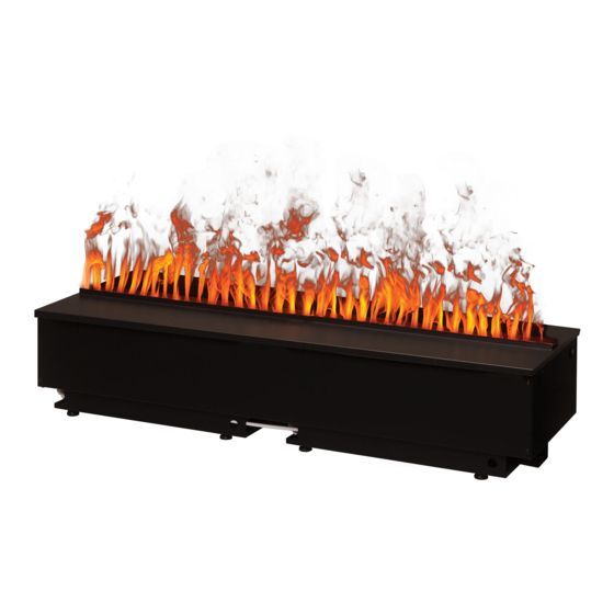
Dimplex CDFI1000P Service Manual
Hide thumbs
Also See for CDFI1000P:
- Owner's manual (19 pages) ,
- Service manual (15 pages) ,
- Owner's manual (21 pages)
Table of Contents
Advertisement
IMPORTANT SAFETY INFORMATION: Always read this manual first before attempting to service this cassette. For your
safety, always comply with all warnings and safety instructions contained in this manual to prevent personal injury or
property damage.
Service Manual
Model
CDFI1000P
CDFI500P
CDFI1000-PRO
CDFI500-PRO
Part Number
6909660100
6909660200
6909660300
6909660400
7400880000R03
Advertisement
Table of Contents

Related Manuals for Dimplex CDFI1000P


Summary of Contents for Dimplex CDFI1000P
- Page 1 Service Manual Model Part Number CDFI1000P 6909660100 CDFI500P 6909660200 CDFI1000-PRO 6909660300 CDFI500-PRO 6909660400 IMPORTANT SAFETY INFORMATION: Always read this manual first before attempting to service this cassette. For your safety, always comply with all warnings and safety instructions contained in this manual to prevent personal injury or property damage.
-
Page 2: Table Of Contents
Replacement Parts List - CDFI1000P, CDFI10000-PRO . . . . . . . . . . . . . . . . . -
Page 3: Operation
(under the media plate), tethered controller (must be connected to the unit) and a remote control. The CDFI1000P and the CDFI1000-PRO units have two separate internal modules that are controlled by the settings entered on the left side (primary). The primary side controls include the power switch and standby button, whereas the secondary side controls do not. -
Page 4: Maintenance
NOTE: If you need to move the unit ensure that all of the components that contain water have been emptied before Battery Cover relocating. Servicing Except for installation and cleaning described in this manual, an authorized service representative should perform any other servicing. www.dimplex.com... -
Page 5: Exploded Parts Diagram - Cdfi1000
Note that if yellow LEDs are used as replacements for earlier MODs with CDFI1000P ....9601110100RP original Main Board, new LED Driver Board (9601270300RP) will need to CDFI1000-PRO . -
Page 6: Exploded Parts Diagram - Cdfi500
Main Board, new LED Driver Board (9601270300RP) will need to CDFI500-PRO ....9601110300RP be installed (included with newer main control boards). All LEDs will need to be changed for colour consistency. www.dimplex.com... -
Page 7: Wiring Diagram
Wiring Diagram CDFI500 BLUE WHITE BROWN BLACK Fuse wire SPEAKER COMMUNICATION LINK DC FAN ELEMENT DC FAN ELEMENT MOTOR MOTOR 24v Input 24v Input RELAY RELAY o p t i o n a l 2 n d o p t i o n a l 2 n d LED DRIVER BOARD LED DRIVER BOARD t r a n s u d c e r... -
Page 8: Switch Board Replacement
7. Re-assemble the remainder of the cassette in reverse 8. Re-assemble the remainder of the cassette in reverse order from the instructions above. order from the instructions above. Figure 4 Switch Board Terminal Block LED Light Assembly Electronics Cover Electronic Choke Main Control Board Power Supply www.dimplex.com... -
Page 9: Fan Assembly Replacement
Fan Assembly Replacement Secondary Side 1. Disconnect and remove the media tray or log set from Tools Required: Phillips head screwdriver the unit and put them in a safe place. WARNING: Disconnect power before attempting any 2. Remove the 4 screws and the electronics cover from maintenance to reduce the risk of electric shock or the unit. -
Page 10: Main Control Board Replacement
CAUTION: Ensure that the switchboard and terminal block have not moved from their original locations and all wires are contained under the cover before reassembly. LED Driver 10. Re-assemble the remainder of the cassette in reverse order from the instructions above. www.dimplex.com... -
Page 11: Led Light Assembly Replacement
Power Supply Replacement 5. Transfer the wires from the old board to the new board. NOTE: A flat head screwdriver can be used to gently pry between the end of the connector and the switch to Tools Required: Phillips head screwdriver release the wires. -
Page 12: Heating Element Replacement
6. Locate the 2 screws that secure the element assembly (element and brackets) to the unit and remove. 7. Lift the element assembly out of the unit. www.dimplex.com... -
Page 13: Level Sensor Assembly Replacement
Level Sensor Assembly Replacement CAUTION: Ensure that the switchboard and terminal block have not moved from their original locations and all Tools Required: Phillips head screwdriver wires are contained under the cover before reassembly. WARNING: Disconnect power before attempting any 13. -
Page 14: Solenoid Valve Replacement
12. Re-assemble the remainder of the cassette in reverse solenoid valve. order from the instructions above. Figure 8 Tether must be installed Floats (one on each post) To CDFILOG (optional) Fan/air filter (not shown) Maximum water level line Minimum water level line www.dimplex.com... -
Page 15: Troubleshooting Guide
Troubleshooting Guide Before you begin consulting the troubleshooting guide, see Figure 8 to ensure the unit is ready for operation. The water level must be between the minimum and maximum water level lines, and the tether must be plugged in. When turning the unit on, ensure that both the power switch has been turned to the ON (I) position and that the standby button has been pressed. - Page 16 Ensure fan filter is clean and dry Fan is not operating correctly - put unit in If fan is not working in test mode, replace fan. If test mode to test the fan issue persists, replace main board www.dimplex.com...
- Page 17 Mist will begin emitting out of the unit after 45 Improper operation seconds of operation Carefully lift the top cover while the unit is oper- Flame is being produced, but is not ris- ating. If mist is produced but is not rising, refer to ing beyong the top cover.
-
Page 18: Test Mode
Off to end the test mode. DATE 21-12-15 31-07-19 07-10-19 08-07-20 1-888-346-7539 | www.dimplex.com In keeping with our policy of continuous product improvement, we reserve the right to make changes without notice. © 2020 Glen Dimplex Americas www.dimplex.com...