Table of Contents
Advertisement
Quick Links
Instructions for TPC Power Through Control Console
SPECIFICATIONS
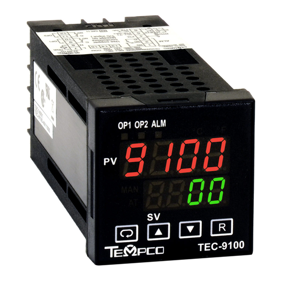
Temperature Controller: Model TEC-9100, 1/16 DIN Dual Display with PID Auto-tuning
Sensor Input: Type "J" or type "K" thermocouple dependent on model ordered
Power Cord/voltage Input: 120VAC or 240VAC (dependent on model ordered)
Heater Output: 12A max for 1-zone consoles
Output Device: Solid State Relay
Main Power Switch: Located on front panel
Fuse Main Power: See replacement parts list (located on back panel)
Fuse Control Power: See replacement parts list (located on back panel)
WARNINGS
1. Air vents located on top and bottom of console must not be blocked! To prevent an
overheating condition the internal components must remain as close to room
temperature (75ºF / 24ºC) as possible.
2. Dangerous voltage capable of causing injury or death is present within this console.
Power to all equipment must be disconnected before installation or beginning any
troubleshooting procedures.
be made by qualified personnel only.
3. To minimize the possibility of fire or shock, do not expose this console to rain or
excessive moisture.
4. Do not use this console in areas where hazardous conditions exist such as excessive
shock, vibration, dirt, corrosive gases, oil or where explosive gases or vapors are
present.
WIRING
(For safety, disconnect all power sources prior to wiring)
1. Attach the leads from your type thermocouple to the mini-plug provided. Take care to
note the correct polarity. The red lead is (-) negative.
2. The heater output current is sourced directly through the line cord. The rear console
output receptacle and mating Hubbell plug provides live controlled power for direct
connection to your heater(s). Connect one lead from your heater to one prong of the
Hubbell plug (not ground). Connect the other lead from your heater to the other prong.
Connect heater ground (if applicable) to the ground connection (G) on the plug.
© Copyright 2020. All Rights Reserved.
1
(Alternative inputs available for special order)
6A max per zone for 2-zone consoles
4A max per zone for 3-zone consoles
3A max per zone for 4-zone consoles
Heater output wiring and component replacement must
Rev. 3/20
D1304.01
Advertisement
Table of Contents

Related Manuals for Tempco TEC-9100


Summary of Contents for Tempco TEC-9100
- Page 1 Instructions for TPC Power Through Control Console SPECIFICATIONS Temperature Controller: Model TEC-9100, 1/16 DIN Dual Display with PID Auto-tuning Sensor Input: Type “J” or type “K” thermocouple dependent on model ordered (Alternative inputs available for special order) Power Cord/voltage Input: 120VAC or 240VAC (dependent on model ordered)
-
Page 2: Operation
2. Set your desired temperature setpoint by using the up and down arrow buttons on the TEC-9100 temperature controller. 3. Refer to the following pages for complete operation and auto-tuning of the TEC-9100 temperature controller. SPARE/REPLACEMENT PARTS Tempco... -
Page 3: Chapter 1 Overview
The following diagram is a comparison of results with and without TEC-9100 is a 1/16 DIN size panel mount controller. TEC-7100 Fuzzy technology. is a 72×72 DIN size panel mount controller. TEC-8100 is a 1/8 DIN size panel mount controller and TEC-4100 is a 1/4 DIN size panel mount controller. -
Page 4: Keys And Displays
2.5 seconds. Press for 7.4 seconds to select auto-tuning mode. The left diagram shows program number 6 for TEC-9100 with version 12. Press for 8.6 seconds to select calibration mode. The program no. for TEC-7100 is 13, for TEC-8100 is 11 and for TEC-4100 is 12. -
Page 5: Menu Overview
1–5 Menu Overview... - Page 6 Parameter Descriptions (TEC-9100 Temperature Controller) NOTE: It is strongly recommended that a process should incorporate a LIMIT CONTROL such as the TEC-910 which will shut down the equipment at a preset process condition in order to preclude possible damage to products or system.
-
Page 7: Chapter 3 Programming
Chapter 3 Programming 3–2 Signal Input Press for 5 seconds and release to enter the setup menu. Press INPT: Selects the sensor type or signal type for signal input. to select the desired parameter. The upper display indicates Range: (thermocouple) J-TC, K-TC, T-TC, E-TC, B-TC, the parameter symbol, and the lower display indicates the selected R-TC, S-TC, N-TC, L-TC value of the parameter. -
Page 8: Digital Filter
PV Shift In certain applications it is desirable to shift the controller display value (PV) from its actual value. This can easily be accomplished by using the PV shift function. The SHIF function will alter PV only. Example: A process is equipped with a heater, a sensor, and a subject to be warmed up. -
Page 9: Auto Tuning
Auto-tuning The auto-tuning process is performed near the set point. The process will oscillate around the set point during the tuning process. Set the set point at a lower value if overshooting beyond the normal process value is likely to cause damage. Auto-tuning is applied in cases of: •... - Page 10 Table A.1 Error Codes and Corrective Actions...
-
Page 11: Warranty
Tempco Electric Heater Corporation is pleased to offer No product returns can be accepted without a completed Return suggestions on the use of its products. However, Tempco makes Material Authorization (RMA) form. no warranties or representations of any sort regarding the fitness TECHNICAL SUPPORT for use, or the application of its products by the Purchaser. - Page 12 Radiant Heaters Strip Heaters Flexible Heaters Tubular Heaters Process Heaters Instrumentation Temperature Control Temperature Sensors 607 N. Central Avenue Wood Dale, IL 60191-1452 USA P: 630-350-2252 Toll Free: 800-323-6859 F: 630-350-0232 E: info@tempco.com www.tempco.com © Copyright 2020. All Rights Reserved...