Table of Contents
Advertisement
Save these instructions for future use!
FAILURE TO READ AND FOLLOW ALL INSTRUCTIONS
CAREFULLY BEFORE INSTALLING OR OPERATING THIS
CONTROL COULD CAUSE PERSONAL INJURY AND/OR
PROPERTY DAMAGE.
APPLICATIONS
THERMOSTAT APPLICATION GUIDE
Description
Heat Pump (No Aux. or Emergency Heat)
Heat Pump (with Aux. or Emergency Heat)
Systems with up to 4 Stages Heat, 2 Stages Cool
Heat Only Systems
Millivolt Heat Only Systems - Floor or Wall Furnaces
Cool Only Systems
Gas or Oil Heat
Electric Furnace
Hydronic (Hot Water) Zone Heat - 2 Wires
Hydronic (Hot Water) Zone Heat - 3 Wires
Wired Remote Temperature Sensor (Indoor or Outdoor)
Dual Fuel Feature (Heat Pump Mode, Outdoor Remote
Required)
SPECIFICATIONS
Electrical Rating:
Battery Power . . . . . . . . . . . . . . . . . . . . . . . . . . mV to 30 VAC, NEC Class II, 50/60 Hz or DC
Input-Hardwire . . . . . . . . . . . . . . . . . . . . . . . . . 20 to 30 VAC
Terminal Load . . . . . . . . . . . . . . . . . . . . . . . . . . . . . 1.5A per terminal, 2.5A maximum all terminals combined
Setpoint Range . . . . . . . . . . . . . . . . . . . . . . . . . . . . 45 to 99°F (7 to 32°C)
Differential (Single Stage) . . . . . . . . . . . . . . . . . . . . Heat 0.6°F; Cool 1.2°F
Differential (Multi-Stage) . . . . . . . . . . . . . . . . . . . . . Heat 0.6°F; Cool 1.2°F
Differential (Heat Pump) . . . . . . . . . . . . . . . . . . . . . Heat 1.2°F; Cool 1.2°F
Operating Ambient. . . . . . . . . . . . . . . . . . . . . . . . . . 32°F to +105°F (0 to +41°C)
Operating Humidity . . . . . . . . . . . . . . . . . . . . . . . . . 90% non-condensing max.
Shipping Temperature Range . . . . . . . . . . . . . . . . . -40 to +150°F (-40 to +65°C)
Dimensions Thermostat. . . . . . . . . . . . . . . . . . . . . . 4.2"H x 6.4"W x 1.7"D
CAUTION
!
To prevent electrical shock and/or equipment damage,
disconnect electric power to system at main fuse or
circuit breaker box until installation is complete.
Index
Blue Universal Thermostat
with Automatic Heat/Cool
Single Stage, Multi-Stage, Heat Pump
Installation and Operating Instructions for Model:
Model
1F95-0671
1F95-0671 Universal Thermostat
Yes
Yes
Yes
Yes
Yes
Yes
Yes
Yes
Yes
Yes
Yes
Yes
ATTENTION: MERCURY NOTICE
This product does not contain mercury. However, this prod-
uct may replace a product that contains mercury.
Mercury and products containing mercury must not be
discarded in household trash. Do not touch any spilled
Page
mercury. Wearing non-absorbent gloves, clean up any
2
spilled mercury and place in a sealed container. For proper
3
disposal of a product containing mercury or a sealed
5
container of spilled mercury, place it in a suitable shipping
6
container. Refer to www.white-rodgers.com for location to
9
send product containing mercury.
10
14
www.white-rodgers.com
Changeover Option
Programming Choices
7 Day
5/1/1 Day
Non-Programmable
PART NO. 37-6979A
0908
Advertisement
Table of Contents

Related Manuals for White Rodgers 1F95-0671


Summary of Contents for White Rodgers 1F95-0671
-
Page 1: Table Of Contents
Installation and Operating Instructions for Model: Model Programming Choices 1F95-0671 7 Day 1F95-0671 Universal Thermostat ATTENTION: MERCURY NOTICE This product does not contain mercury. However, this prod- uct may replace a product that contains mercury. Mercury and products containing mercury must not be discarded in household trash. -
Page 2: Installation
If the Power Stealing Assist method is not compatible with your system, place the Power Stealing Switches to "Off". This cancels Power Stealing Assist, operates the thermostat on batteries and corrects the condition. ® or Ener- Figure 1 – 1F95-0671 Mounting Hole Place Level Switch Position/Description Switches "On", thermostat runs on batteries. -
Page 3: Wiring Diagrams
WIRING DIAGRAMS Refer to equipment manufacturers' instructions for specifi c system wiring information. After wiring, see CONFIGURA- TION section for proper thermostat confi guration. Terminal Designation Description O/B ... Changeover valve for heat pump energized constantly in cooling and off/heating Y2 ... - Page 4 WIRING DIAGRAMS System Heat Pump 1 Energized in (HP1) Cool Mode Diagnostic Heat and Indicator Cool Mode or System 1st Stage Heat Pump 2 Energized in Malfunction (Compressor) Heat, Off, Switch (HP2) Emergency Mode Comfort Alert II Module or Similar System Diagnostic Module See Module Instructions for details...
-
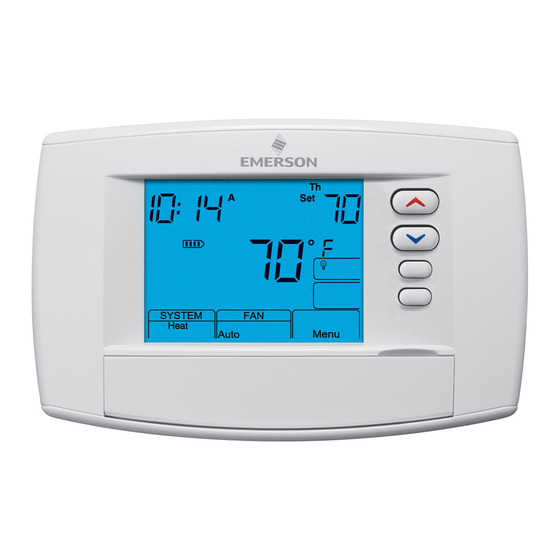
Page 5: Thermostat Quick Reference
THERMOSTAT QUICK REFERENCE Home Screen Description Battery Level Indicator Indicating the current power level of the 2 “AA” batteries: Full power remaining. Half power remaining Change The batteries should be replaced at this time with 2 new premium brand “AA” Alkaline batteries. (See page 2 for more details) Programming and Confi... -
Page 6: Installer Confi Guration Menu
INSTALLER/CONFIGURATION MENU Thermostat must be in Heat, Cool or Auto. Press and hold the Menu button for at least 5 seconds. The display will show item #1 in the table below. Press Menu to advance to the next menu item. Press Menu HP SS Press... - Page 7 INSTALLER/CONFIGURATION MENU 20 18 MENU dS (On) 21 19 MENU (OFF) Keypad Lockout MENU (000) Keypad Lockout 22 20 MENU L Heat (99) 23 21 MENU L Cool (45) – MENU (05) MENU (dF) MENU (60) – MENU (80) 26 22 MENU Change Filter (OFF) MENU...
- Page 8 INSTALLER/CONFIGURATION MENU 5, 6 & 7) Cycle Rate Selection – The factory default setting for Heat and Cool modes, SS1, MS2, is medium cycle (ME). For Heat Pump, HP1, HP2, the default setting is medium (ME). For Emer (Aux) the default setting is fast cycle (FA). To change cycle rate, press the Cycle rate differentials for different settings are: MODE...
-
Page 9: Operating Your Thermostat
INSTALLER/CONFIGURATION MENU 24) Limited Cool Range – This feature provide a minimum setpoint temperature for cool. The default setting is 45°F. It can be changed between 46°F and 82°F by pressing the button. 25) Select Compressor Off (CO) Feature Using Outdoor Sensor –... -
Page 10: Programming
OPERATING YOUR THERMOSTAT Emergency System EM bypasses the Heat Pump to use the heat source wired to terminal W/E on the thermostat. EM is typically used when compressor operation is not desired, or you prefer back-up heat only. 1. Press SYSTEM button to select EM. “EM” will fl ash on the display. - Page 11 PROGRAMMING Energy Saving Factory Pre-Program The 1F95-0680 thermostats are programmed with the energy saving settings shown in the table below for all days of the week. If this program suits your needs, simply set the thermostat clock and press the RunSched button. The table below shows the factory set heating and cooling schedule for all days of the week.
-
Page 12: Enter The Cooling Program
PROGRAMMING Automatic Daylight Saving Calculation The Real Time Clock will adjust automatically for daylight sav- ings time, in the following manner: Increment one hour at 2 AM on the second Sunday of March and decrement one hour at 2 AM on the fi rst Sunday of No- vember. -
Page 13: Wired Remote Temperature Sensing
PROGRAMMING Wired Remote Temperature Sensing One remote temperature sensor can be installed indoor or outdoor and connected to the thermostat by a maximum cable length of 100 meters (300 feet). Terminals +, S and - on the terminal block allow connection of the remote sensor. The thermostat must have 24 VAC Common connection to terminal C for the remote sensor to operate. -
Page 14: Troubleshooting
TROUBLESHOOTING Reset Operation Note: When thermostat is reset, installer confi guration menu settings and programming will reset to factory settings. If a voltage spike or static discharge blanks out the display or causes erratic thermostat operation, you can reset the thermo- stat by removing the wires from terminals R and C (do not short them together) and removing batteries for 2 minutes. - Page 15 NOTES...
- Page 16 HOMEOWNER HELP LINE: 1-800-284-2925 White-Rodgers is a division of Emerson Electric Co. The Emerson logo is a trademark and service mark www.white-rodgers.com of Emerson Electric Co.