Table of Contents
Advertisement
Save these instructions for future use!
FAILURE TO READ AND FOLLOW ALL INSTRUCTIONS
CAREFULLY BEFORE INSTALLING OR OPERATING THIS
CONTROL COULD CAUSE PERSONAL INJURY AND/OR
PROPERTY DAMAGE.
APPLICATIONS
THERMOSTAT APPLICATION GUIDE
Thermostat
Configuration Options
Gas, Oil, Electric, Heat Only,
Cool Only or Heat/Cool
No Heat Pump (SS1)
Systems, 2 or 3 wire Hydronic
Zone (Hot Water or Steam)
Systems, 24 Volt or Millivolt
Single Stage Compressor
Single Stage Compressor
Heat Pump Systems - up to 2
Heat Pump (HP1)
Stages Aux./Emergency Heat
Heat Pump 2
Two Stage or Two Compressor
Two Stage or Two
Heat Pump systems - up to 2
Compressor Heat Pump
Stages Aux./Emergency Heat
(HP2)
SPECIFICATIONS
Electrical Rating:
Battery Power . . . . . . . . . . . . . . . . . . . . . . . . . . mV to 30 VAC, NEC Class II, 50/60 Hz or DC
Input-Hardwire . . . . . . . . . . . . . . . . . . . . . . . . . 20 to 30 VAC
Terminal Load . . . . . . . . . . . . . . . . . . . . . . . . . . . . . 1.5A per terminal, 2.5A maximum all terminals combined
Setpoint Range . . . . . . . . . . . . . . . . . . . . . . . . . . . . 45 to 99°F (7 to 32°C)
Rated Differentials:
Heat (Single Stage/Multi Stage) . . . . . . . . . . . . 0.4 °F
Cool (Single Stage/Multi Stage) . . . . . . . . . . . . 0.9 °F
Heat Pump . . . . . . . . . . . . . . . . . . . . . . . . . . . . 0.9 °F
Aux. Heat . . . . . . . . . . . . . . . . . . . . . . . . . . . . . 0.6 °F
Operating Ambient. . . . . . . . . . . . . . . . . . . . . . . . . . 32°F to +105°F (0 to +41°C)
Operating Humidity . . . . . . . . . . . . . . . . . . . . . . . . . 90% non-condensing max.
Shipping Temperature Range . . . . . . . . . . . . . . . . . -40 to +150°F (-40 to +65°C)
Dimensions Thermostat. . . . . . . . . . . . . . . . . . . . . . 4-3/16"H x 6-1/2"W x 1-5/8"D
CAUTION
!
To prevent electrical shock and/or equipment damage,
disconnect electric power to system at main fuse or
circuit breaker box until installation is complete.
Index
Maximum
Thermostat
Stages
Applications
Heat/Cool
1/1
2/2
3/1
4/2
Page
2
2
3
4
5
7
8
www.white-rodgers.com
www.emersonclimate.com
Blue Easy Reader Thermostat
Single Stage, Multi-Stage, Heat Pump
Installation Instructions for Model:
Model
1F95EZ-0671
Non-Programmable
1F95EZ-0671 Thermostat
Fast
Med.
Slow
0.6 °F
1.7 °F
1.2 °F
1.7 °F
1.2 °F
1.7 °F
-
1.7 °F
ATTENTION: MERCURY NOTICE
This product does not contain mercury. However, this
product may replace a product that contains mercury.
Mercury and products containing mercury must not be
discarded in household trash. Do not touch any spilled
mercury. Wearing non-absorbent gloves, clean up any
spilled mercury and place in a sealed container. For
proper disposal of a product containing mercury or a
sealed container of spilled mercury, place it in a suitable
shipping container. Refer to www.white-rodgers.com for
location to send product containing mercury.
Programming Choices
7 Day
PART NO. 37-6986B
Replaces 37-6986A
1023
Advertisement
Table of Contents

Related Manuals for White Rodgers 1F95EZ-0671


Summary of Contents for White Rodgers 1F95EZ-0671
-
Page 1: Table Of Contents
Thermostat Quick Reference Installer Configuration Menu Operating Your Thermostat Troubleshooting Blue Easy Reader Thermostat Single Stage, Multi-Stage, Heat Pump Installation Instructions for Model: Model 1F95EZ-0671 Non-Programmable 1F95EZ-0671 Thermostat Maximum Stages Heat/Cool Fast Med. Slow 0.6 °F 1.7 °F 1.2 °F 1.7 °F... -
Page 2: Single Stage
If the Power Stealing Assist method is not compatible with your system, place the Power Stealing Switches to "Off". This cancels Power Stealing Assist, operates the thermostat on batteries and corrects the condition. Figure 1 – Thermostat Base Multi-Stage 1F95EZ-0671 Mounting Hole across Mounting Tabs... -
Page 3: Wiring Diagrams
WIRING DIAGRAMS Figure 2 – Single Stage, SS1, or Multi-Stage, MS2, System (No Heat Pump) System Single Diagnostic Energized Constantly Stage 1 Indicator (SS1) Input Cool Mode System Multi- Malfunction Energized Constantly Stage 2 Switch in Heat, Off, (MS2) Input Emergency Mode Comfort Alert II Module... -
Page 4: Product View
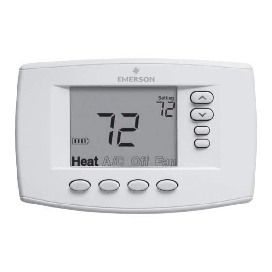
THERMOSTAT QUICK REFERENCE Home Screen Description Battery Level Indicator Indicating the current power level of the 2 “AA” batteries. Full power remaining. Half power remaining. Change The batteries should be replaced at this time with 2 new premium brand “AA” Alkaline batteries. (See page 2 for more details). -
Page 5: Installer Configuration Menu
INSTALLER/CONFIGURATION MENU With Heat or A/C selected, press and hold the Menu button for at least 5 seconds. The display will show item #1 in the table below. Press Menu to advance to the next menu item. Press Menu HP SS Press Displayed Ref. - Page 6 INSTALLER/CONFIGURATION MENU 1) This control can be configured for: MS 2 – Multi-Stage System (no heat pump) HP 1 – Heat Pump with one stage of compressor, Gas or Electric backup HP 2 – Heat Pump with two stage compressor or two compressor system, Gas or Electric backup SS 1 –...
-
Page 7: Operating Your Thermostat
OPERATING YOUR THERMOSTAT Check Thermostat Operation NOTE To prevent static discharge problems, touch side of thermostat to release static build-up before touching any keys. If at any time during testing your system does not operate properly, contact a qualified service person. Fan Operation If your system does not have a G terminal connection, skip to Heating System. -
Page 8: Troubleshooting
TROUBLESHOOTING Reset Operation Note: When thermostat is reset, installer configuration menu settings and programming will reset to factory settings. If a voltage spike or static discharge blanks out the display or causes erratic thermostat operation, you can reset the thermo- stat by removing the wires from terminals RH and RC (do not short them together) and removing batteries for 2 minutes.