Advertisement
Table of Contents
- 1 Attach Thermostat Base to Wall
- 2 Battery Location
- 3 Electric/Gas Switch
- 4 Mounting and Wiring
- 5 Wiring Diagrams
- 6 Multi-Stage Terminal Outputs
- 7 Check Thermostat Operation
- 8 Thermostat Buttons and Switches
- 9 Operation
- 10 Configuration Menu
- 11 Installer/Configuration Menu
- 12 Specifications
- 13 Electrical Data
- 14 Thermal Data
- 15 Programming Your Thermostat
- 16 Troubleshooting
- Download this manual
See also:
Instruction Manual
Operator: Save these instructions for future use!
Operator: Save these instructions for future use!
Operator: Save these instructions for future use!
Operator: Save these instructions for future use!
Operator: Save these instructions for future use!
FAILURE TO READ AND FOLLOW ALL INSTRUCTIONS CAREFULLY BEFORE
FAILURE TO READ AND FOLLOW ALL INSTRUCTIONS CAREFULLY BEFORE
FAILURE TO READ AND FOLLOW ALL INSTRUCTIONS CAREFULLY BEFORE
FAILURE TO READ AND FOLLOW ALL INSTRUCTIONS CAREFULLY BEFORE
FAILURE TO READ AND FOLLOW ALL INSTRUCTIONS CAREFULLY BEFORE
INSTALLING OR OPERATING THIS CONTROL COULD CAUSE PERSONAL
INSTALLING OR OPERATING THIS CONTROL COULD CAUSE PERSONAL
INSTALLING OR OPERATING THIS CONTROL COULD CAUSE PERSONAL
INSTALLING OR OPERATING THIS CONTROL COULD CAUSE PERSONAL
INSTALLING OR OPERATING THIS CONTROL COULD CAUSE PERSONAL
INJURY AND/OR PROPERTY DAMAGE.
INJURY AND/OR PROPERTY DAMAGE.
INJURY AND/OR PROPERTY DAMAGE.
INJURY AND/OR PROPERTY DAMAGE.
INJURY AND/OR PROPERTY DAMAGE.
YOUR THERMOSTAT REPLACES
YOUR THERMOSTAT REPLACES
YOUR THERMOSTAT REPLACES
YOUR THERMOSTAT REPLACES
YOUR THERMOSTAT REPLACES
Description
Description
Description
Description
Description
Heat Pump (No Aux. or Emergency Heat)
Heat Pump (with Aux. or Emergency Heat)
Standard Heat & Cooling Systems
Two Stage Heat & Two Stage Cool
Standard Heat Only Systems
Millivolt Heat Only Systems – Floor or Wall Furnaces
Standard Central Air Conditioning
Gas or Oil Heat
Electric Furnace
Hydronic (Hot Water) Zone Heat – 2 Wires
Hydronic (Hot Water) Zone Heat – 3 Wires
CAUTION
!
To prevent electrical shock and/or equipment dam-
To prevent electrical shock and/or equipment dam-
To prevent electrical shock and/or equipment dam-
To prevent electrical shock and/or equipment dam-
To prevent electrical shock and/or equipment dam-
age, disconnect electric power to system at main fuse
age, disconnect electric power to system at main fuse
age, disconnect electric power to system at main fuse
age, disconnect electric power to system at main fuse
age, disconnect electric power to system at main fuse
or circuit breaker box until installation is complete.
or circuit breaker box until installation is complete.
or circuit breaker box until installation is complete.
or circuit breaker box until installation is complete.
or circuit breaker box until installation is complete.
Before removing wires from old thermostat's switching sub-
base, label each wire
label each wire
label each wire
label each wire
label each wire with the terminal designation it was
removed from.
1. Shut off electricity at the main fuse box until installation is
complete. Ensure that electrical power is disconnected.
2. Remove Old Thermostat
Remove Old Thermostat: A standard heat/cool
Remove Old Thermostat
Remove Old Thermostat
Remove Old Thermostat
thermostat consists of three basic parts:
a. The cover, which may be either a snap-on or
hinge type.
b. The base, which is removed by loosening all
captive screws.
c. The switching subbase, which is removed by
unscrewing the mounting screws that hold it on
the wall or adaptor plate.
3. Remove the front cover of the old thermostat. With
wires
wires
wires still attached
wires
wires
still attached, remove wall plate from the wall. If
still attached
still attached
still attached
the old thermostat has a wall mounting plate, remove the
thermostat and the wall mounting plate as an assembly.
4. Identify each wire attached to the old thermostat.
5. Disconnect the wires from the old thermostat one at a
time. DO NOT LET WIRES FALL BACK INTO THE
DO NOT LET WIRES FALL BACK INTO THE
DO NOT LET WIRES FALL BACK INTO THE
DO NOT LET WIRES FALL BACK INTO THE
DO NOT LET WIRES FALL BACK INTO THE
WALL
WALL
WALL.
WALL
WALL
6. Install new thermostat using the following procedures.
1F85-277
1F85-277
1F85-277
1F85-277
1F85-277
Yes
Yes
Yes
Yes
Yes
Yes
Yes
Yes
Yes
Yes
No
With
With
With
With
White-Rodgers is a division
of Emerson Electric Co.
www.white-rodgers.com
1F85-277
1F85-277
1F85-277
1F85-277
1F85-277
Heating & Air Conditioning
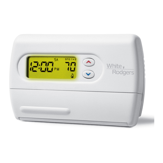
7 Day/5-1-1 Programmable/Non-programmable, Auto
Changeover, Multi-Stage/Heat Pump Thermostat
INSTALLATION INSTRUCTIONS
INSTALLATION INSTRUCTIONS
INSTALLATION INSTRUCTIONS
INSTALLATION INSTRUCTIONS
INSTALLATION INSTRUCTIONS
Assemble tools required as shown below.
FLAT BLADE SCREWDRIVER
HAND OR POWER
DRILL WITH 3/16 INCH
DRILL BIT, IF NEEDED
REMOVING OLD THERMOSTAT
REMOVING OLD THERMOSTAT
REMOVING OLD THERMOSTAT
REMOVING OLD THERMOSTAT
REMOVING OLD THERMOSTAT
Mounting
Hole
Figure 1 – Thermostat base
Figure 1 – Thermostat base
Figure 1 – Thermostat base
Figure 1 – Thermostat base
Figure 1 – Thermostat base
ATTENTION!
ATTENTION!
ATTENTION!
ATTENTION! This product does not contain mercury. How-
ATTENTION!
ever, this product may replace a unit which contains mercury.
Do not open mercury cells. If a cell becomes damaged, do not
touch any spilled mercury. Wearing non-absorbent gloves,
clean up the spilled mercury and place into a container which
can be sealed. If a cell becomes damaged, the unit should be
discarded.
Mercury must not be discarded in household trash. When the
unit this product is replacing is to be discarded, place in a
suitable container and return to White-Rodgers at 2895 Harrison
Street, Batesville, AR 72501 for proper disposal.
PREPARATIONS
PREPARATIONS
PREPARATIONS
PREPARATIONS
PREPARATIONS
WIRE CUTTER/STRIPPER
Y2
C
R
E/W1
Y1
O
B
L W2 G
Mounting
Hole
ELEC.
GAS
Elec-Gas
Switch
ON
AUTO
not
not
not
not
PART NO. 37-6560A
PART NO. 37-6560A
PART NO. 37-6560A
PART NO. 37-6560A
PART NO. 37-6560A
0430
Advertisement
Table of Contents

Related Manuals for White Rodgers 1F85-277


Summary of Contents for White Rodgers 1F85-277
- Page 1 WALL WALL. WALL WALL 6. Install new thermostat using the following procedures. White-Rodgers is a division of Emerson Electric Co. www.white-rodgers.com 1F85-277 1F85-277 1F85-277 1F85-277 1F85-277 Heating & Air Conditioning 7 Day/5-1-1 Programmable/Non-programmable, Auto Changeover, Multi-Stage/Heat Pump Thermostat INSTALLATION INSTRUCTIONS...
-
Page 2: Attach Thermostat Base To Wall
MOUNTING AND WIRING MOUNTING AND WIRING MOUNTING AND WIRING MOUNTING AND WIRING MOUNTING AND WIRING WARNING Do not use on circuits exceeding specified voltage. Do not use on circuits exceeding specified voltage. Do not use on circuits exceeding specified voltage. Do not use on circuits exceeding specified voltage. -
Page 3: Wiring Diagrams
Reversing Valve Reversing 2nd Stage Energized in Valve Compressor Heat, Off, Energized in Emergency Cool Mode Compressor Mode Contactor Figure 4. Typical wiring diagram for two transformer heat pump systems with safety circuits in BOTH systems *The 24 volt neutral connection to terminal C on the thermostat is not required if you replace the batteries once a year with fresh “AA” Energizer Refer to equipment manufacturers' instructions for specific system wiring information. -
Page 4: Multi-Stage Terminal Outputs
Refer to equipment manufacturers' instructions for specific system wiring information. You can configure the thermostat for use with either multi-stage electric heat systems or multi-stage gas systems. When con- figured for electric electric electric electric heat, the G G G G G terminal (blower/fan) will be electric energized on a call for heat. -
Page 5: Thermostat Buttons And Switches
Before you begin programming your thermostat, you should be familiar with its features and with the display and the location and operation of the thermostat buttons. Your thermostat consists of two parts: the thermostat cover and the base. To remove the cover, pull it straight out from the base. To replace the cover, line up the cover with the base and press until the cover snaps onto the base. -
Page 6: Installer/Configuration Menu
CONFIGURATION MENU CONFIGURATION MENU CONFIGURATION MENU CONFIGURATION MENU CONFIGURATION MENU Press the SYSTEM button until OFF INSTALLER/CONFIGURATION MENU INSTALLER/CONFIGURATION MENU INSTALLER/CONFIGURATION MENU INSTALLER/CONFIGURATION MENU INSTALLER/CONFIGURATION MENU Press Press Press Displayed Displayed Displayed Press Press Displayed Displayed Step Step Button(s) Button(s) (Factory Default) (Factory Default) Step... - Page 7 5) Select Energy Management Recovery OFF or ON Select Energy Management Recovery OFF or ON Select Energy Management Recovery OFF or ON Select Energy Management Recovery OFF or ON – Select Energy Management Recovery OFF or ON Energy Management Recovery (EMR) causes the thermo- stat to start heating or cooling early to make the building temperature reach the program setpoint at the time you specify.
-
Page 8: Specifications
SPECIFICA SPECIFICA TIONS TIONS SPECIFICA SPECIFICATIONS SPECIFICA TIONS TIONS ELECTRICAL DATA ELECTRICAL DATA ELECTRICAL DATA ELECTRICAL DATA ELECTRICAL DATA Electrical Rating Electrical Rating Electrical Rating Electrical Rating Electrical Rating: 20 to 30 VAC 50/60 Hz or DC 0.05 to 1.5 Amps (Load per terminal) 2.5 Amps Maximum Total Load (All terminals combined) OPERA OPERA... -
Page 9: Programming Your Thermostat
PROGRAMMING YOUR THERMOSTAT PROGRAMMING YOUR THERMOSTAT PROGRAMMING YOUR THERMOSTAT PROGRAMMING YOUR THERMOSTAT PROGRAMMING YOUR THERMOSTAT This section will help you plan your thermostat's program to meet your needs. For maximum comfort and efficiency, keep the following guidelines in mind when planning your program. •... -
Page 10: Troubleshooting
OPERATION OPERA OPERA OPERA OPERA TION TION TION TION heating program period appears. The time will change in 15- minute increments. When your selected time is displayed, press TIME again to return to the change temperature mode. 5. Press PRGM once. The currently programmed start time and setpoint temperature for the Monday’s 2nd heating program period will appear. - Page 11 Possible Cause Possible Cause Symptom Symptom Possible Cause Possible Cause Possible Cause Symptom Symptom Symptom 5. Heating system requires service or No Heat (continued) thermostat requires replacement. (continued) 1. SYSTEM button not pressed to COOL. No Cool 2. Loose connection to thermostat or system.
- Page 12 TROUBLESHOOTING TROUBLESHOOTING TROUBLESHOOTING TROUBLESHOOTING TROUBLESHOOTING Possible Cause Symptom Symptom Symptom Symptom Symptom Forgot Keypad Lockout Code (continued) First stage is keeping up with demand. Why won’t my 2nd or 3rd stage come on? F F F F F A A A A A Q Q Q Q Q Symptom Symptom Symptom...