Table of Contents
Advertisement
Quick Links
Advertisement
Table of Contents

Related Manuals for Lorex LW2232


Summary of Contents for Lorex LW2232
- Page 1 INSTRUCTION MANUAL ENGLISH VERSION 1.0...
- Page 2 Installation (Continued) Service Ventilation Servicing - Slots and openings in the case are - Do not attempt to service this video provided for ventilation to ensure reliable operation equipment yourself, as opening or removing covers of the product and to protect it from overheating. may expose you to dangerous voltage or other These openings must not be blocked or covered.
- Page 3 Features • Real time wireless video with MPEG-4 compression at 640x480 (VGA) resolution • Single 2 channel receiver minimizes cable clutter and offers greater value. • Extended bandwidth delivers smooth high frame rate video. • SignalGuard™ Technology continuously monitors the wireless signal and automatically reconnects upon detecting low signal strength.
-
Page 4: Table Of Contents
Table of Contents 1. Getting Started ....... . . 1 2. - Page 5 Attention This device uses the antenna with RP-SMA connector which must be professionally installed.
-
Page 6: Getting Started
(PRE-ATTACHED) (Mounting kit contents may differ from image) WIRELESS SECURITY CAMERAS INSTRUCTION MANUAL ENGLISH VERSION 1.0 LW2232 www.lorextechnology.com INSTRUCTION MANUAL 2 X DOUBLE-SIDED TAPE QUICK START GUIDE CHECK YOUR PACKAGE TO CONFIRM THAT YOU HAVE RECEIVED THE COMPLETE SYSTEM, INCLUDING ALL COMPONENTS SHOWN ABOVE. -
Page 7: Wireless Receiver
Wireless Receiver 2. Wireless Receiver Removable Antennas (SMA Type): Pre-attached to the receiver. Channel Indicator LEDs: Glow green to indicate which channel is selected for pairing. Pairing Button: For details, see “Pairing Cameras” on page 8. DC Power: Connect power adapter to power on the receiver. -
Page 8: Wireless Camera
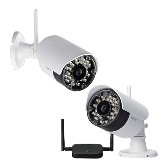
Wireless Camera 3. Wireless Camera Removable Antenna (SMA Type): Pre-attached to the back of camera. Camera Stand DC Power: Connect power adapter to power on the camera. Pairing Button: For details, see “Pairing Cameras” on page 8. Antenna Jack ATTENTION - This camera includes an Auto Mechanical IR Cut Filter. -
Page 9: Installing The Camera
Installing the Camera 4. Installing the Camera Cameras are suitable for outdoor installation. Installation in a sheltered location is recommended. For example, install under shelter protected from the elements, such as beneath roof eaves. The diagram to the right shows an example of an ideal location for outdoor placement. -
Page 10: Mounting Positions
Installing the Camera 4.2 Mounting Positions You may mount your cameras on a wall, ceiling, or counter. See the images below for recommended configurations of the camera stand and antenna. Wall Ceiling Counter NOTE: For ceiling installation, position the antenna as high as the ceiling allows. See the "Ceiling"... - Page 11 Installing the Camera Loosen the thumbscrews (1, 2) and the adjustment ring (3) by turning them counter clockwise. Adjust the angle of the cameras until the desired view is set. Tighten the thumbscrews and the adjustment ring to secure each camera’s position. Connect the power cable from the cameras to the weatherproof power connector.
-
Page 12: Installing The Wireless Receiver
Installing the Wireless Receiver 5. Installing the Wireless Receiver Before powering on the receiver, make sure to first connect and power on the cameras. This will ensure a proper connection. Connect the BNC cables labelled CAM1 and CAM2 to your DVR. Channel Indicator LED’s Connect the power cable to the power adapter. -
Page 13: Pairing Cameras
Pairing Cameras 6. Pairing Cameras IMPORTANT The cameras and the receiver have already been paired out of the box, which means that they are exclusively communicating with each other. If for some reason the pairing is lost, follow these steps to pair the cameras and receiver. To pair the cameras to the receiver: Make sure that the cameras and receiver are both powered up and all antennas are properly attached. -
Page 14: Appendix A: System Specifications
Appendix A: System Specifications 7. Appendix A: System Specifications 7.1 General Specifications TX Frequency Range 2.400GHz~2.480GHz TX Power 16dBm Unobstructed Effective Range 165ft (50m) indoor 500ft (152m) outdoor Data Rate 4 Mb/s Modulation GFSK Spread Spectrum FHSS Operating Temperature Range 14°F ~ 122°F / -10°C ~ 40°C 1. -
Page 15: Appendix B: Frequently Asked Questions
The signal range also depends on whether there are competing signals using the same frequency as the camera. For example, signals from cordless phones or routers may affect signal strength. Adaptive Frequency Hopping Spread Spectrum (FHSS) technology featured in the latest Lorex models greatly reduces signal interference. Range Limiting Factors Reflection... -
Page 16: Are Digital Wireless Camera Signals Secure
8.5 How many frames per second should I expect from a digital wireless camera? Current Lorex digital wireless cameras offer 10 - 30 FPS (Frames Per Second) performance. Actual frame rate depends mainly on signal strength (see the chart in section above). -
Page 17: Appendix C: Troubleshooting
Appendix C: Troubleshooting 9. Appendix C: Troubleshooting If you have problems with your system, there is often a quick and simple solution. Please try the following: Problem Solution There is no picture from the • Make sure that the camera is plugged into a power outlet and that camera(s) the power adapter is plugged in properly. -
Page 18: Appendix D: Extending Wireless Signal Range
Appendix D: Extending Wireless Signal Range 10. Appendix D: Extending Wireless Signal Range DISCLAIMER: Certain accessories are not available in all markets. There are several ways to boost your wireless signal as well as options to help you extend the range of the wireless signal. Clear Line-of-Sight You should always try to ensure there is a clear line-of-sight between the camera and the receiver. - Page 19 Appendix D: Extending Wireless Signal Range 2.4 GHZ Directional Wireless Panel Antenna Use the 2.4GHz Directional Wireless Panel Antenna (model #: ACCANTD9) to focus a wireless signal onto one specific camera in order to increase the range of transmission (clear line-of-sight between the camera and the antenna is required).
- Page 20 Note : Cet appareil est conforme à la Partie 15 des règlements de la FCC et aux normes RSS de l’Industrie du Canada. Son fonctionnement est soumis aux deux conditions suivantes : (1) cet appareil ne doit pas causer des interférences nuisibles, et (2) cet appareil doit accepter toute interférence reçue, y compris les interférences qui peuvent provoquer un fonctionnement indésirable.