
Related Manuals for Intel ESM-APLC


Summary of Contents for Intel ESM-APLC
- Page 1 ESM-APLC Intel® Celeron® / Pentium® SoC Processor Type 6 COMe Compact Module User’s Manual Ed – 28 July 2017 Copyright Notice Copyright 2017 ALL RIGHTS RESERVED. Part No. E2047288500R...
- Page 2 We assume no responsibility or liability for the use of the described product(s), conveys no license or title under any patent, copyright, or masks work rights to these products, and makes no representations or warranties that 2 ESM-APLC User’s Manual...
- Page 3 ESM-APLC User’s Manual these products are free from patent, copyright, or mask work right infringement, unless otherwise specified. Applications that are described in this manual are for illustration purposes only. We make no representation or warranty that such application will be suitable for the specified use without further testing or modification.
-
Page 4: Table Of Contents
2.4.2.1.12 USB Signals ........................27 2.4.2.1.13 I2C Signals ........................27 2.4.2.1.14 COM.0 Pins Signals ....................... 27 2.4.3 COM Express Connector 2 (CN1B) ....................28 2.4.3.1 Signal Description – COM Express Connector 2 (CN1B) ............32 2.4.3.1.1 USB3.0 Signals ........................32 4 ESM-APLC User’s Manual... - Page 5 ESM-APLC User’s Manual 2.4.3.1.2 DDI Signals .......................... 32 Installing COMe Module + Heatsink / Heat spreader & Carrier board ..... 33 Installing COMe Module & Carrier board ..............34 3.BIOS Setup ........................35 Introduction ......................36 Starting Setup ......................36 Using Setup ......................
- Page 6 Install Chipset Driver ....................76 Install TXE Driver ....................77 Install VGA Driver ....................78 Install Audio Driver ....................79 Install Serial IO Driver ..................... 80 Install Ethernet Driver ....................81 5. Mechanical Drawing ....................83 6 ESM-APLC User’s Manual...
-
Page 7: Getting Started
1.2 Packing List Before you begin installing your single board, please make sure that the following materials have been shipped: 1 x ESM-APLC COMe Module 1 x Driver/Utility DVD-ROM 1 x Desiccant (5g) ... -
Page 8: Document Amendment History
ESM-APLC User’s Manual 1.3 Document Amendment History Revision Date Comment July 2017 Initial Release 8 ESM-APLC User’s Manual... -
Page 9: Manual Objectives
We strongly recommend that you study this manual carefully before attempting to set up ESM-APLC series or change the standard configurations. Whilst all the necessary information is available in this manual we would recommend that unless you are confident, you contact your supplier for guidance. -
Page 10: System Specifications
ESM-APLC User’s Manual 1.5 System Specifications System Onboard Intel® Celeron® N3350 Processor / Pentium® N4200 SoC Processor Apollo Lake Platform Celeron® N3350 1.1GHz/6W Pentium® N4200 1.1GHz/6W BIOS AMI uEFI BIOS, 128Mbit SPI Flash ROM System Chipset Apollo Lake SoC integrated... - Page 11 Support Linux (Kernel>4.5) Implementing the new thermal design conception which adds the screw hole next to the SoC to fix the thermal module. Thermal Solution Heatsink w/o Fan Heat spreader Note: Specifications are subject to change without notice. ESM-APLC User’s Manual 11...
-
Page 12: Architecture Overview-Block Diagram
ESM-APLC User’s Manual 1.6 Architecture Overview—Block Diagram The following block diagram shows the architecture and main components of ESM-APLC. eDP to LVDS CH7511B Resistor Select DP to VGA DDI_1 SWITCH CH7517A 8 USB2.0 DDI_0 4 USB3.0 3 PCIe x 1... -
Page 13: Hardware Configuration
ESM-APLC User’s Manual 2. Hardware Configuration ESM-APLC User’s Manual 13... -
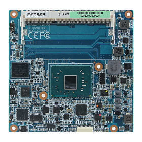
Page 14: Product Overview
ESM-APLC User’s Manual 2.1 Product Overview 14 ESM-APLC User’s Manual... -
Page 15: Installation Procedure
6. Enter the BIOS setup by pressing the delete key during boot up. Use the "Save & Exit \ Restore Defaults" feature. 7. If TFT panel display is to be utilized, make sure the panel voltage is correctly set before connecting the display cable and turning on the power. ESM-APLC User’s Manual 15... -
Page 16: Main Memory
ESM-APLC User’s Manual 2.2.1 Main Memory ESM-APLC provides the 204-pin SODIMM socket, supports up to 8GB DDR3L 1866 SDRAM SODIMM Make sure to unplug the power supply before adding or removing DIMMs or other system components. Failure to do so may cause severe damage to board and components. - Page 17 (2) Static electricity can damage the electronic components of the computer or optional boards. Before proceeding, ensure that you are discharged of static electricity by briefly touching a grounded metal object. ESM-APLC User’s Manual 17...
-
Page 18: Connector List
The following tables list the function of each of the board’s jumpers and connectors. Connectors Label Function Note (Reserved for BIOS programming) 5 x 2 header, pitch 2.00mm BIOS_SPI1 CN1A COM Express connector 1 COM Express connector 2 CN1B SODIMM1 204-pin DDR3L SDRAM DIMM socket AT/ATX mode selector 18 ESM-APLC User’s Manual... -
Page 19: Setting Jumpers & Connectors
ATX mode *Default 2.4.1.1 Signal Description –AT/ATX mode selection AT/ATX mode Description AT mode Auto-power on, no need to press Power button to enable power on/off ATX mode Press the power button to enable power on/off ESM-APLC User’s Manual 19... -
Page 20: Com Express Connector 1 (Cn1A)
FST_SPI_D3 SER0_TX FST_SPI_D2 TYPE10# CB_SPI_CS# PP_TPM VGA_I2C_DAT FST_SPI_D0/MOSI VGA_I2C_CK FST_SPI_CLK VGA_VSYNC GPO0/SD_CLK VGA_HSYNC FST_SPI_D1/MISO VGA_BLU +1.8VSB VGA_GRN PCIE_CLK_REF- VGA_RED PCIE_CLK_REF+ BIOS_DIS1# CB_EDP_HDP +ATX5VSB +ATX5VSB GPI3/SD_DATA3 +ATX5VSB LVDS_I2C_DAT/EDP_AUX- A84 +ATX5VSB LVDS_BKLT_CTRL/ LVDS_I2C_CK/EDP_AUX+ EDP_BKLT_CTRL LVDS_A_CK-/EDP_TX3- LVDS_B_CK- LVDS_A_CK+/EDP_TX3+ LVDS_B_CK+ 20 ESM-APLC User’s Manual... - Page 21 GPO3/SD_CD# PCIE_TX2- A62 B62 PCIE_RX2- PCIE_TX2+ A61 B61 PCIE_RX2+ A60 B60 PCIE_TX3- PCIE_RX3- A59 B59 PCIE_TX3+ A58 B58 PCIE_RX3+ A57 B57 GPO2/SD_WP A56 B56 A55 B55 GPI0/SD_DATA0 A54 B54 GPO1/SD_CMD A53 B53 A52 B52 A51 B51 ESM-APLC User’s Manual 21...
- Page 22 A33 B33 I2C_CLK HDA_BITCLK A32 B32 SPKR A31 B31 HDA_RST# HDA_SDI0 A30 B30 HDA_SYNC A29 B29 SATA_ACT# A28 B28 BATLOW# A27 B27 A26 B26 A25 B25 PCH_SLP_S4# A24 B24 PWR_OK A23 B23 A22 B22 A21 B21 22 ESM-APLC User’s Manual...
- Page 23 SUS_S3# A15 B15 SMB_ALERT# A14 B14 SMB_SDA_S5 GBE0_MDI0+ A13 B13 SMB_SCL_S5 GBE0_MDI0- A12 B12 PWRBTN# A11 B11 GBE0_MDI1+ A10 B10 LPC_CLKOUT1 GBE0_MDI1- GBE0_LINK# GBE0_MDI2+ LPC_AD3 GBE0_MDI2- LPC_AD2 GBE0_LINK1000# A5 LPC_AD1 GBE0_LINK100# LPC_AD0 GBE0_MDI3+ LPC_FRAME# GBE0_MDI3- GBE0_ACT# ESM-APLC User’s Manual 23...
-
Page 24: Signal Description - Com Express Connector 1 (Cn1A)
GBE0_Lin1000# Gigabit Ethernet Controller 0 1000 Mbit / sec link indicator, active low. 2.4.2.1.3 PCI Express Signals Signal Signal Description PCIE_TX[0:3] +/- PCI Express Differential Transmit Pair 0-3 PCIE_RX[0:3] +/- PCI Express Differential Receive Pair 0-3 24 ESM-APLC User’s Manual... -
Page 25: Flat Panel Lvds Signals
Module High Module SPI0/SPI1 BIOS_DIS1# Carrier Module Module High Module Module Carrier SPI0 Carrier SPI0/SPI1 Carrier Module SPI1 Module SPI0/SPI1 2.4.2.1.7 GPIO Signals Signal Signal Description GPI[0:4] General purpose input pins. GPO[0:4] General purpose output pins. ESM-APLC User’s Manual 25... -
Page 26: Power Signals
Management Interrupt) or to wake the system. SUS_STAT# Indicates imminent suspend operation. PWR_OK Power OK from main power supply SYS_RESET# Reset button input. Active low input. WAKE0# PCI Express wake up signal. WAKE1# General purpose wake up signal. 26 ESM-APLC User’s Manual... -
Page 27: Sata Signals
I2C_CLK General purpose I2C port clock output. I2C_DATA General purpose I2C port data I/O line. 2.4.2.1.14 COM.0 Pins Signals Signal Signal Description SER0/1_TX TTL level outputs from the Module. SER0/1_RX TTL level inputs from the Module. ESM-APLC User’s Manual 27... -
Page 28: Com Express Connector 2 (Cn1B)
ESM-APLC User’s Manual 2.4.3 COM Express Connector 2 (CN1B) Signal Signal C110 D110 C109 D109 C108 D108 C107 D107 C106 D106 C105 D105 C104 D104 C103 D103 C102 D102 C101 D101 C100 D100 28 ESM-APLC User’s Manual... - Page 29 C67 D67 C66 D66 C65 D65 C64 D64 C63 D63 C62 D62 C61 D61 C60 D60 C59 D59 C58 D58 TYPE1# C57 D57 TYPE2# C56 D56 C55 D55 TYPE0# C54 D54 C53 D53 C52 D52 C51 D51 ESM-APLC User’s Manual 29...
- Page 30 C34 D34 DDI1_DDC_AUX_SEL DDI2_CTRLDATA_AUX- C33 D33 DDI1_PAIR2- DDI2_CTRLCLK_AUX+ C32 D32 DDI1_PAIR2+ C31 D31 C30 D30 DDI1_PAIR1- C29 D29 DDI1_PAIR1+ C28 D28 C27 D27 DDI1_PAIR0- C26 D26 DDI1_PAIR0+ C25 D25 DDI1_HPD C24 D24 C23 D23 C22 D22 C21 D21 30 ESM-APLC User’s Manual...
- Page 31 C17 D17 C16 D16 DDI1_CTRLDATA_AUX- C15 D15 DDI1_CTRLCLK_AUX+ C14 D14 USB_SSRX3+ C13 D13 USB_SSTX3+ USB_SSRX3- C12 D12 USB_SSTX3- C11 D11 USB_SSRX2+ C10 D10 USB_SSTX2+ USB_SSRX2- USB_SSTX2- USB_SSRX1+ C7 USB_SSTX1+ USB_SSRX1- USB_SSTX1- USB_SSRX0+ C4 USB_SSTX0+ USB_SSRX0- USB_SSTX0- ESM-APLC User’s Manual 31...
-
Page 32: Signal Description - Com Express Connector 2 (Cn1B)
DP AUX+function if DDI[1:2]_DDC_AUX_SEL is no connect DDI[1:2]_CTRLCLK_AUX+ HDMI/DVI 12C CTRLCLK if DDI[1:2]_DDC_AUX_SEL is pulled high DP AUX-function if DDI[1:2]_DDC_AUX_SEL is no connect DDI[1:2]_CTRLDATA_AUX- HDMI/DVI 12C CTRLDATA if DDI[1:2]_DDC_AUX_SEL is pulled high DDI[1:2]_HPD Digital Display Interface Hot-Plug Detect 32 ESM-APLC User’s Manual... -
Page 33: Installing Come Module + Heatsink / Heat Spreader & Carrier Board
Step1. Using 2 screws (M2.5-4L) to lock the Heatsink/Heat spreader from PCB backside. Step2. Using 4 screws (M2.5-12L) to assemble with Carrier board from top to bottom. Note: Recommendation of screwing torque force: 4kg Screw Size / Q’TY - M2.5-4L Ni * 2pcs - M2.5-12L Ni * 4pcs ESM-APLC User’s Manual 33... -
Page 34: Installing Come Module & Carrier Board
ESM-APLC User’s Manual 2.6 Installing COMe Module & Carrier board Step1. Using 4 screws (M2.5-6L) to lock the Carrier board. Note: Recommendation of screwing torque force: 4kg Screw Size / Q’TY: M2.5-6L Ni * 4pcs 34 ESM-APLC User’s Manual... -
Page 35: Bios Setup
ESM-APLC User’s Manual 3.BIOS Setup ESM-APLC User’s Manual 35... -
Page 36: Introduction
If the message disappears before you respond and you still wish to enter Setup, restart the system to try again by turning it OFF then ON or pressing the "RESET" button on the system case. You may also restart by simultaneously pressing <Ctrl>, <Alt>, and <Delete> keys. 36 ESM-APLC User’s Manual... -
Page 37: Using Setup
Note: Some of the navigation keys differ from one screen to another. To Display a Sub Menu Use the arrow keys to move the cursor to the sub menu you want. Then press <Enter>. A “” pointer marks all sub menus. ESM-APLC User’s Manual 37... -
Page 38: Getting Help
Even a seemingly small change to the chipset setup has the potential for causing you to use the override. 38 ESM-APLC User’s Manual... -
Page 39: Bios Setup
<Enter> to accept and enter the sub-menu. 3.6.1 Main Menu This section allows you to record some basic hardware configurations in your computer and set the system clock. ESM-APLC User’s Manual 39... -
Page 40: System Language
Note: The BIOS setup screens shown in this chapter are for reference purposes only, and may not exactly match what you see on your screen. 3.6.2 Advanced Menu This section allows you to configure your CPU and other system devices for basic operation through the following sub-menus. 40 ESM-APLC User’s Manual... -
Page 41: Trusted Computing
Enable[Default] and INT1A interface will not be available. Physical Presence Spec Select to Tell O.S. to support PPI Spec Version 1.2 or Version 1.3[Default], 1.3. Note some HCK tests might not support 1.3. 3.6.2.2 APCI Settings ESM-APLC User’s Manual 41... -
Page 42: Smart Settings
Select WatchDog. 1 min 2 min 10 min 30 min Disabled Enable/Disable USB Standby Power during USB Standby Power Setting Enabled[Default], S3/S4/S5. Disabled Wake Up By Ring Wake Up by Ring from S3/S4/S5. Enabled[Default], 3.6.2.3 SMART Settings 42 ESM-APLC User’s Manual... -
Page 43: Nct6106D Super Io Configuration
Please refer to 3.6.2.3.1~ 3.6.2.3.3 for more information. Item Description Serial Port 1 Configuration Set Parameters of Serial Port 1 (COMA). Serial Port 2 Configuration Set Parameters of Serial Port 2 (COMB). Parallel Port Configuration Set Parameters of Parallel Port (LTP/LPTE). ESM-APLC User’s Manual 43... -
Page 44: Serial Port 1 Configuration
ESM-APLC User’s Manual 3.6.2.4.1 Serial Port 1 Configuration Item Option Description Enabled[Default], Serial Port Enable or Disable Serial Port (COM). Disabled 3.6.2.4.2 Serial Port 2 Configuration 44 ESM-APLC User’s Manual... -
Page 45: Parallel Port Configuration
Enable or Disable Parallel Port (LPT/LPTE). Disabled STD Printer Mode[Default] SPP Mode EPP-1.9 and SPP Mode Device Mode EPP-1.7 and SPP Mode Change the Printer Port mode. ECP Mode ECP and EPP 1.9 Mode ECP and EPP 1.7 Mode ESM-APLC User’s Manual 45... -
Page 46: H/W Monitor
ESM-APLC User’s Manual 3.6.2.5 H/W Monitor Item Option Description Enabled, Smart Fan Function Enables or Disables Smart Fan. Disabled[Default] 46 ESM-APLC User’s Manual... -
Page 47: It8528Sec Super Io Configuration
Please refer to 3.6.2.6.1~ 3.6.2.6.2 for more information. Item Description Serial Port 1 Configuration Set Parameters of Serial Port 1 (COMA). Serial Port 2 Configuration Set Parameters of Serial Port 2 (COMB). 3.6.2.6.1 Serial Port 1 Configuration ESM-APLC User’s Manual 47... -
Page 48: Serial Port 2 Configuration
Item Option Description Enabled[Default], Serial Port Enable or Disable Serial Port (COM). Disabled 3.6.2.6.2 Serial Port 2 Configuration Item Option Description Enabled[Default], Serial Port Enable or Disable Serial Port (COM). Disabled 3.6.2.7 Serial Port Console Redirection 48 ESM-APLC User’s Manual... -
Page 49: Com0
Space Parity do not allow for error detection. They can be used as an additional data bit. Stop bits indicate the end of a serial data 1[Default] Stop Bits packet. (A start bit indicates the beginning). The standard setting is 1 stop bit. ESM-APLC User’s Manual 49... -
Page 50: Legacy Console Redirection Settings
OS. When Always Enable Redirection After BIOS POST BootLoader is selected, then Legacy Console Redirection is enabled for legacy OS. Default setting for this option is set to Always Enable. 3.6.2.7.2 Legacy Console Redirection Settings 50 ESM-APLC User’s Manual... -
Page 51: Console Redirection Settings
Hardware RTS/CTS be sent to stop the data flow. Once the buffers are empty, a ‘start’ signal can be sent Software Xon/Xoff to re-start the flow. Hardware flow control uses two wires to send start/stop signals. ESM-APLC User’s Manual 51... -
Page 52: Cpu Configuration
Item Options Description Disabled[Default] Number of cores to enable in each processor Active Processor Cores Enabled package. When enabled, a VMM can utilize the additional Disabled Intel Virtualization Technology hardware capabilities provided by Vanderpool Enabled[Default] Technology. 52 ESM-APLC User’s Manual... -
Page 53: Socket 0 Cpu Information
ESM-APLC User’s Manual 3.6.2.8.1 Socket 0 CPU Information 3.6.2.8.2 CPU Power Management Configuration Item Option Description Disabled EIST Enable/Disable Intel SpeedStep. Enabled[Default] ESM-APLC User’s Manual 53... -
Page 54: Network Stack Configuration
Core C6 Core C1 Unlimited Disabled C-State Auto Demotion Configure C-State Auto Demotion. C1[Default] Disabled C-State Un-demotion Configure C-State Un-demotion. C1[Default] 3.6.2.9 Network Stack Configuration Item Options Description Enabled Network Stack Enable/Disable UEFI Network Stack. Disabled[Default] 54 ESM-APLC User’s Manual... - Page 55 Ipv6 HTTP Support Disabled[Default] HTTP boot option will not be created. Wait time to press ESC key to abort the PXE PXE boot wait time boot. Number of times presence of media will be Media detect count checked. ESM-APLC User’s Manual 55...
-
Page 56: Csm Configuration
ESM-APLC User’s Manual 3.6.2.10 CSM Configuration Item Options Description Enabled CSM Support Enable/Disable CSM Support. Disabled[Default] 56 ESM-APLC User’s Manual... - Page 57 Legacy[Default] Do not launch Controls the execution of UEFI and Legacy Video UEFI Video OpROM. Legacy[Default] Do not launch Determines OpROM execution policy for Other PCI devices UEFI devices other than Network, Storage, or Legacy[Default] Vide. ESM-APLC User’s Manual 57...
-
Page 58: Usb Configuration
‘Auto’ uses default value: for a Root port it is Device power-up delay Manual 100ms, for a Hub port the delay is taken form Hub descriptor. Mass storage device emulation type. ‘AUTO’ Mass Storage Devices Auto[Default] 58 ESM-APLC User’s Manual... -
Page 59: Security Configuration
‘CDROM’, drives with no media will be Hard Disk CD-ROM emulated according to a drive type. 3.6.2.12 Security Configuration Item Options Description Enabled TXE HMRFPO TXE HMRFPO. Disabled[Default] Enabled[Default] TXE EOP Message Send EOP Message Before Enter OS. Disabled ESM-APLC User’s Manual 59... -
Page 60: Chipset
ESM-APLC User’s Manual 3.6.3 Chipset 3.6.3.1 North Bridge Item Option Description 2 GB[Default] Max TOLUD Maximum Value of TOLUD. 2.25 GB 60 ESM-APLC User’s Manual... -
Page 61: South Bridge
Above 4GB MMIO BIOS assignment Disabled[Default] automatically when Aperture Size is set to 2048MB. 3.6.3.2 South Bridge Item Option Description Quiet Serial IRQ Mode Configure Serial IRQ Mode. Continuous[Default] Windows[Default] OS Selection Android Select the target OS. Intel Linux ESM-APLC User’s Manual 61... -
Page 62: Uncore Configuration
Active LVDS (Ch7511) Enabled[Default] LVDS(eDP->Ch7511-to-LVDS). 1024x768 24/1[Default] 800x600 18/1 1024x768 18/1 1366x768 18/1 1024x600 18/1 Port1-EDP to LVDS(Chrotel 7511) Panel CH7511 EDID Panel Option 1280x800 18/1 EDID Option. 1920x1200 24/2 1920x1080 18/2 1280x1024 24/2 1440x900 18/2 1600x1200 24/2 62 ESM-APLC User’s Manual... -
Page 63: South Cluster Configuration
ESM-APLC User’s Manual 1366x768 24/1 1920x1080 24/2 1680x1050 24/2 LVDS Back Light PWM Select LVDS back light PWM duty. 100%[Default] 200[Default] LVDS Back Light PWM Select LVDS back light PWM Frequency. Frequency 3.6.3.4 South Cluster Configuration ESM-APLC User’s Manual 63... -
Page 64: Hd-Audio Configuration
ESM-APLC User’s Manual 3.6.3.4.1 HD-Audio Configuration Item Option Description Disable HD-Audio Support Enable/Disable HD-Audio Support. Enable[Default] 3.6.3.4.2 PCI Express Configuration 64 ESM-APLC User’s Manual... -
Page 65: Pci Express Root Port (Rtl8111)
Enable PCIe root port Disabled PCIe root port. Disable[Default] PCI Express Active State Power ASPM Management settings. L0sL1 Auto Disabled[Default] L1.1 L1 Substates PCI Express L1 Substates settings. L1.2 L1.1 & L1.2 Auto[Default] PCIe Speed Gen1 Configure PCIe Speed. Gen2 ESM-APLC User’s Manual 65... -
Page 66: Pci Express Root Port 4
Enable PCIe root port Disabled PCIe root port. Disable[Default] PCI Express Active State Power ASPM Management settings. L0sL1 Auto Disabled[Default] L1.1 L1 Substates PCI Express L1 Substates settings. L1.2 L1.1 & L1.2 Auto[Default] PCIe Speed Gen1 Configure PCIe Speed. Gen2 66 ESM-APLC User’s Manual... -
Page 67: Pci Express Root Port 5
Enable PCIe root port Disabled PCIe root port. Disable[Default] PCI Express Active State Power ASPM Management settings. L0sL1 Auto Disabled[Default] L1.1 L1 Substates PCI Express L1 Substates settings. L1.2 L1.1 & L1.2 Auto[Default] PCIe Speed Gen1 Configure PCIe Speed. Gen2 ESM-APLC User’s Manual 67... -
Page 68: Pci Express Root Port 6(I211)
Enable PCIe root port Disabled PCIe root port. Disable[Default] PCI Express Active State Power ASPM Management settings. L0sL1 Auto Disabled[Default] L1.1 L1 Substates PCI Express L1 Substates settings. L1.2 L1.1 & L1.2 Auto[Default] PCIe Speed Gen1 Configure PCIe Speed. Gen2 68 ESM-APLC User’s Manual... -
Page 69: Sata Drivers
Identify the SATA port is connected to Solid SATA Device Type Solid State Drive State Drive or Hard Disk Drive. Disabled[Default] Enable/Disable SATA Port 0 DevSlp. Board SATA Port 0 DevSlp Enabled rework for LP needed before enable. ESM-APLC User’s Manual 69... -
Page 70: Scc Configuration
ESM-APLC User’s Manual 3.6.3.4.4 SCC Configuration Item Option Description Enable SCC SD Card Support (D27:F0) Enable/Disable SCC SD Card Support. Disable[Default] Enable SCC eMMC Support (D28:F0) Enable/Disable SCC eMMC Support. Disable[Default] 3.6.3.4.4 USB Configuration 70 ESM-APLC User’s Manual... -
Page 71: Security
Compliance Mode. Set TRUE to disable Compliance Mode. USB HW MODE AFE Enable Enable/Disable USB HW MODE AFE Comparators Disable[Default] Comparators. 3.6.4 Security Setup Administrator Password Set setup Administrator Password User Password Set User Password ESM-APLC User’s Manual 71... -
Page 72: Secure Boot
Secure Boot Mode – Custom_Standard, Set UEFI Secure Boot Mode to STANDARD mode Standard[Default] Secure Boot Mode or CUSTOM mode, this change is effect after Customized save. And after reset, the mode will return to STANDARD mode. 72 ESM-APLC User’s Manual... -
Page 73: Key Management
Allow to provision factory default Secure Provision Factory Default Keys Enable Boot keys when System is in Setup Mode. 3.6.5 Boot Item Option Description Number of seconds to wait for setup activation Setup Prompt Timeout 1~ 65535 ESM-APLC User’s Manual 73... -
Page 74: Save And Exit
This option restores all BIOS settings to the factory default. This option is useful if the controller exhibits unpredictable behavior due to an incorrect or inappropriate BIOS setting. 3.6.6.4 Launch EFI Shell from filesystem device Attempts to Launch EFI Shell application (Shellx64.efi) from one of the available filesystem devices. 74 ESM-APLC User’s Manual... -
Page 75: Drivers Installation
ESM-APLC User’s Manual 4. Drivers Installation Note: Installation procedures and screen shots in this section are for your reference and may not be exactly the same as shown on your screen. ESM-APLC User’s Manual 75... -
Page 76: Install Chipset Driver
Windows 10 operation system. If the warning message Step 3. Click Install. appears while the installation process, click Continue to go on. Step1. Click Next. Step 4. Complete setup. Step 2. Click Accept. 76 ESM-APLC User’s Manual... -
Page 77: Install Txe Driver
If the warning message appears while the installation Step 3. Click Next to continue installation. process, click Continue to go on. Step 4. Click Finish to complete setup. Step1. Click Next to start installation. Step 2. Click Next. ESM-APLC User’s Manual 77... -
Page 78: Install Vga Driver
Windows 10 operation system. Step 3. Click Next. Step 1. Click Next to continue installation. Step 4. Click Next. Step 2. Step 5. Click Finish to complete setup. Click Yes to accept license agreement. 78 ESM-APLC User’s Manual... -
Page 79: Install Audio Driver
4.4 Install Audio Driver Note: The installation procedures and screen shots in this section are based on Windows 10 operation system. Step 1. Click Next to continue setup. Step 2. Click Finish to complete the setup. ESM-APLC User’s Manual 79... -
Page 80: Install Serial Io Driver
Windows 10 operation system. Step 3. Click Next to continue setup. Step 1. Click Next to continue setup. Step 4. Click Next. Step 2. Click Next. Step 5. Click Finish to complete the setup. 80 ESM-APLC User’s Manual... -
Page 81: Install Ethernet Driver
Windows 10 operation system. Step 3. Click Next to continue setup. Step 4. Click Next. Step 1. Click Install Drivers and Software. Step 5. Click Install. Step 2. Click Next. ESM-APLC User’s Manual 81... - Page 82 ESM-APLC User’s Manual Step 6. Click Finish to complete the setup. 82 ESM-APLC User’s Manual...
-
Page 83: Mechanical Drawing
ESM-APLC User’s Manual 5. Mechanical Drawing ESM-APLC User’s Manual 83... - Page 84 ESM-APLC User’s Manual Unit: mm 84 ESM-APLC User’s Manual...