Table of Contents
Advertisement
Quick Links
Application
The IOM37 input/output expansion module is a part of the
Metasys
system Field Equipment Controller family. Input/
®
Output Module (IOM) expansion modules expand the
number of I/O points connected to a Network Automation
Engine (NAE), Network Control Engine (NCE), Field
Equipment Controller (FEC), VAV Modular Assembly (VMA),
or Advanced Application Field Equipment Controller (FAC)
to monitor and control a wide variety of HVAC equipment.
IOM expansion modules operate on an RS-485 BACnet
MS/TP Bus and integrate into Johnson Controls
third-party BACnet systems.
Note: At CCT Release 10.1 and later, a new capability
was introduced allowing VMAs, FECs, and FACs to
communicate by using either the BACnet or the N2
field bus networking protocol. The operation of the
Input/Output Module (IOM) is not affected by the
selection of the BACnet or the N2 protocol in the host
controller, when the (IOM) is connected to the host
controller using the SA bus. Only the BACnet protocol
is supported when the (IOM) is connected directly to
the trunk using the FC bus.
Important: In Metasys system smoke control
applications, use only the MS-IOM3710-0U and MS-
IOM3711-0U at Metasys Release 8.1 that are UL 864
UUKL/UUKLC 10th Edition Smoke Control Listed. For
Metasys system smoke control applications, you must
refer to the Metasys System UL 864 UUKL Tenth Edition
Smoke Control System Technical Bulletin (LIT-12012487)
for detailed requirements and procedures for
installing, commissioning, and operating UL 864
UUKL Listed Metasys system devices. The UL 864
UUKL listing for Smoke Control Equipment is voided
if (1) you do not use the required software tools
at the required versions; or (2) you do not meet
the requirements or do not follow the procedures
as documented in the Metasys System UL 864 UUKL
Tenth Edition Smoke Control System Technical Bulletin
(LIT-12012487).
North American Emissions Compliance
Canada
This Class (A) digital apparatus meets all the
requirements of the Canadian Interference-Causing
Equipment Regulations.
Cet appareil numérique de la Classe (A) respecte toutes
les exigences du Règlement sur le matériel brouilleur du
Canada.
IOM3711 Input/Output Module Installation Guide
and
®
United States
This equipment has been tested and found to comply
with the limits for a Class A digital device pursuant to
Part 15 of the FCC Rules. These limits are designed
to provide reasonable protection against harmful
interference when this equipment is operated in a
commercial environment. This equipment generates,
uses, and can radiate radio frequency energy and, if not
installed and used in accordance with the instruction
manual, may cause harmful interference to radio
®
communications. Operation of this equipment in a
residential area may cause harmful interference, in which
case the users will be required to correct the interference
at their own expense.
Installation
Observe these guidelines when installing an expansion
module:
• Transport the expansion module in the original
container to minimize vibration and shock damage.
• Verify that all parts shipped with the expansion module.
• Do not drop the expansion module or subject it to
physical shock.
Parts included
• One expansion module with removable terminal blocks
(Power and SA/FC bus are removable)
• One installation instructions sheet
Materials and special tools needed
• Three fasteners appropriate for the mounting surface
(M4 screws or #8 screws)
• One 20 cm (8 in.) or longer piece of 35 mm DIN rail and
appropriate hardware for DIN rail mount (only)
• Small straight-blade screwdriver for securing wires in
the terminal blocks
Physical feature graphic and table
Part No. 24-10144-84 Rev. N
2019-10-01
*241014484N*
(barcode for factory use only)
MS-IOM3711-x
Advertisement
Table of Contents

Related Manuals for Johnson Controls IOM3711


Summary of Contents for Johnson Controls IOM3711
- Page 1 • Do not drop the expansion module or subject it to applications, use only the MS-IOM3710-0U and MS- physical shock. IOM3711-0U at Metasys Release 8.1 that are UL 864 UUKL/UUKLC 10th Edition Smoke Control Listed. For Parts included Metasys system smoke control applications, you must refer to the Metasys System UL 864 UUKL Tenth Edition •...
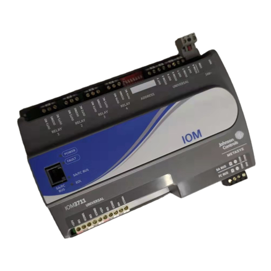
- Page 2 Figure 1: IOM3711 physical features Table 1: IOM3711 Physical features • Mount the expansion module on a hard, even surface whenever possible in wall-mount applications. Callo Physical features: description and references • Use shims or washers to mount the expansion module securely and evenly on the mounting surface.
-
Page 3: Wall Mount Applications
(if necessary). Hold the expansion module in place, and insert the screws through the mounting clips and into the holes (or anchors). Carefully tighten all of the screws. IOM3711 Input/Output Module Installation Guide... - Page 4 FC bus (Figure 4). The SA bus supervisor supplies jack. 15 VDC to devices on the SA bus requiring power. When connecting the IOM to an FC bus, wire the bus terminal block plugs on the expansion module, and the IOM3711 Input/Output Module Installation Guide...
- Page 5 In addition to the wiring guidelines in Table 2, observe these guidelines when wiring expansion module inputs and outputs: • Run all low-voltage wiring and cables separate from high-voltage wiring. IOM3711 Input/Output Module Installation Guide...
- Page 6 • Inputs/outputs with cables less than 30 m (100 ft) typically do not require an offset in the software setup. Cable runs over 30 m (100 ft) may require an offset in the input/output software setup. IOM3711 Input/Output Module Installation Guide...
- Page 7 Qualified Sensors: 0-2k ohm potentiometer, RTD (1k Nickel See Guideline A in Table 3. [ Johnson Controls sensor], 1k Platinum, and A99B Silicon Temperature Sensor) Negative Temperature Coefficient (NTC) Sensor (10k Type L, 10k JCI Type II, 2.252k Type II) Binary Input - Dry Contact Maintained Mode See Guideline A in Table 3.
- Page 8 0.5 mm (24 AWG) stranded copper 61 m (200 ft) twisted wire output point. See Figure 8 to determine See Figure 8 to select wire size/gauge. cable length. Use twisted Use stranded copper wire wire cable. IOM3711 Input/Output Module Installation Guide...
- Page 9 FC or SA Bus Signal Reference and 15 VDC Common retractable cable or 24 AWG 3-pair (Port) Commissioning Converter or ZFR181x/ZFR 182x Wireless CAT 3 Cable <30.5 m (100 ft) Router (Maximum total current draw for SA Bus is 240 mA.) IOM3711 Input/Output Module Installation Guide...
- Page 10 MS/TP bus communications at 38,400 baud. For more information, refer to the MS/TP Communications Bus Technical Bulletin (LIT-12011034). • See Table 3 to determine wire size and cable lengths for cables. IOM3711 Input/Output Module Installation Guide...
- Page 11 Termination details A set of Johnson Controls termination diagrams provides details for wiring inputs and outputs to the controllers. See the figures in this section for the applicable termination diagrams. Table 5: Termination Details Type of Input/ Type of Field Device...
- Page 12 Current Input - External Source (in Loop) Feedback from EPP-100 Dry Contact (Binary Input) 24 VAC Binary Output (Switch UO or RO Low, External Source) 24 VAC Binary Output (Switch UO or RO High, External Source IOM3711 Input/Output Module Installation Guide...
- Page 13 Termination diagrams Output 0–10 VDC Output to Actuator (External Source) 0–10 VDC Output to Actuator (Internal Source) Incremental Control to Actuator(Switch Low, Externally Sourced) Incremental control to Actuator (Switch High, Externally Sourced) Voltage (Analog Output) IOM3711 Input/Output Module Installation Guide...
-
Page 14: Setup And Adjustments
128 to ON for wireless FC bus applications only. To set the device addresses on Metasys field expansion modules: Set all of the switches on the address DIP switch block (128 through 1) to off. IOM3711 Input/Output Module Installation Guide... - Page 15 Table 6 describes the FC bus and SA bus devices addresses for Johnson Controls MS/TP communications To remove the expansion module cover: bus applications. Refer to the MS/TP Communications Bus Technical Bulletin...
- Page 16 Off Steady = No Data Transmission (N/A - auto baud not supported) On Steady = Communication lost, waiting to join communication ring Off (Except on On Steady = EOL switch in ON position Amber terminating Off Steady = EOL switch in Off position devices) IOM3711 Input/Output Module Installation Guide...
-
Page 17: Repair Information
For a replacement expansion module, contact your Johnson Controls representative. For the MS-IOM3710-0U and MS-IOM3711-0U models that are UL 864 10th Edition UUKL/ORD-C100-13 UUKLC listed for smoke control, contact the Johnson Controls Repair Center in Louisville, Kentucky, at 1-502-671-7312. - Page 18 Refer to the WRZ Series Wireless Room Sensors Product Bulletin (LIT-12000653) for specific sensor WRZ Series Wireless Room Sensors model descriptions. Refer to the Mobile Access Portal Gateway Catalog Page (LIT-1900869) to identify the appropriate Mobile Access Portal (MAP)Gateway product for your region. IOM3711 Input/Output Module Installation Guide...
-
Page 19: Technical Specifications
24 VAC (nominal, 20 VAC minimum/30 VAC maximum), 50/60 Hz, power supply Class 2 (North Supply Voltage America), Safety Extra-Low Voltage (SELV) (Europe) 14 VA maximum for IOM3711 only Note: VA rating does not include any power supplied to the peripheral devices connected to Power Consumption Binary Outputs (BOs) or Configurable Outputs (COs), which can consume up to 12 VA for each BO or CO;... -
Page 20: Product Warranty
DISTRICT WUXI JIANGSU PROVINCE 214028 CHINA For more contact information, refer to www.johnsoncontrols.com/locations. © 2019 Johnson Controls. All rights reserved. All specifications and other information shown were current as of document revision and are subject to change without notice. www.johnsoncontrols.com...