Milwaukee 4253-1 Operator's Manual
Heavy-duty drill motors, electromagnetic drill stands, electromagnetic drill presses
Hide thumbs
Also See for 4253-1:
- Operator's manual (32 pages) ,
- Operator's manual (32 pages) ,
- Operator's manual (21 pages)
Table of Contents
Advertisement
Available languages
Available languages
Cat. No. / No de cat.
4253-1, 4262-1, 4292-1, 4297-1, 4204-1,
4206-1, 4208-1, 4210-1, 4202, 4203
HEAVY-DUTY DRILL MOTORS, ELECTROMAGNETIC DRILL STANDS,
ELECTROMAGNETIC DRILL PRESSES
PERCEUSES ÉLECTROMAGNÉTIQUES, COLONNES ET MOTEURS DE
PERCEUSES EXTRA ROBUSTES
MOTORES PARA TALADRADORAS EXTRARESISTENTES, BASES
ELECTROMAGNÉTICAS PARA TALADRADORAS, PRENSAS
TALADRADORAS ELCTROMAGNÉTICAS
WARNING
AVERTISSEMENT
comprendre le manuel.
ADVERTENCIA
To reduce the risk of injury, user must read and understand operator's manual.
Afin de réduire le risque de blessures, l'utilisateur doit lire et bien
Para reducir el riesgo de lesiones, el usuario debe leer y entender el manual.
OPERATOR'S MANUAL
MANUEL de L'UTILISATEUR
MANUAL del OPERADOR
Advertisement
Table of Contents

Related Manuals for Milwaukee 4253-1


Summary of Contents for Milwaukee 4253-1
- Page 1 OPERATOR'S MANUAL MANUEL de L'UTILISATEUR MANUAL del OPERADOR Cat. No. / No de cat. 4253-1, 4262-1, 4292-1, 4297-1, 4204-1, 4206-1, 4208-1, 4210-1, 4202, 4203 HEAVY-DUTY DRILL MOTORS, ELECTROMAGNETIC DRILL STANDS, ELECTROMAGNETIC DRILL PRESSES PERCEUSES ÉLECTROMAGNÉTIQUES, COLONNES ET MOTEURS DE PERCEUSES EXTRA ROBUSTES MOTORES PARA TALADRADORAS EXTRARESISTENTES, BASES ELECTROMAGNÉTICAS PARA TALADRADORAS, PRENSAS...
-
Page 2: General Power Tool Safety Warnings
GENERAL POWER TOOL • Do not overreach. Keep proper footing and SAFETY WARNINGS balance at all times. This enables better control of the power tool in unexpected situations. Read all safety warnings, instruc- WARNING • Dress properly. Do not wear loose clothing or tions, illustrations and specifica- jewelry. -
Page 3: Extension Cords
Milwaukee Tool or a trained properly grounded. Do not modify the plug pro- professional for additional information or training. -
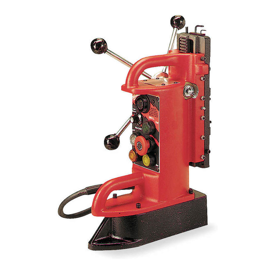
Page 4: Specifications
All drills (except jury, always keep hands, rags, cloth- 4253-1) can also be mounted in a reverse position ing, etc. away from moving parts and to permit drilling close to walls and corners. When chips. -
Page 5: Operation
1. Select the mounting area that Auto Base/Chip De-Mag best suits your application. (Motor must be OFF) 2. Line up the mounting holes. The metal chips formed while drilling have a tendency 3. Slip the lock washers over to retain some residual magnetism and stick to the the mounting screw and base once the electromagnet is de-energized. - Page 6 B - Forward Drill Button Safety Chain C - Reverse Drill Button To reduce the risk of injury,always WARNING The drill may be set to two positions: forward and use a safety chain when drilling reverse. overhead or on a vertical surface. 1.
- Page 7 These drills are supplied with a No. 3 Morse Taper Chuck" or "Morse Taper Socket" and "Using Twist Socket. Drills" and "Using MILWAUKEE STEEL HAWG™ To insert a bit or adapter into the socket: Cutters"). 1. Make sure the taper is clean and 2.
- Page 8 Excessive pressure will only slow the operation Using MILWAUKEE STEEL HAWG™ CUTTERS and damage the cutter. Use less feed pressure MILWAUKEE STEEL HAWG™ CUTTERS cut an when slotting or notching because there is less annular ring around the edge of the hole leaving support for the cutting edges in these situations.
-
Page 9: Maintenance
When the product was modified or repaired by people not authorized is determined by MILWAUKEE to be defective in material or workman- by TECHTRONIC INDUSTRIES. ship for a period of five (5) years** after the date of purchase unless Note: If cord set is damaged, it should be replaced by an Authorized otherwise noted. -
Page 10: Sécurité Électrique
SÉCURITÉ INDIVIDUELLE IMPORTED AND COMMERCIALIZED BY TECHTRONIC INDUSTRIES MEXICO, SA DE CV • Rester attentif, prêter attention au travail et faire Av President Masarik #29 piso 7, Col. Polanco V Sección preuve de bon sens lors de l'utilisation de tout outil CP 11560, Deleg. -
Page 11: Entretien
Ne pas utiliser cet outil si vous ne comprenez pas ces instructions d’opération ou si vous pensez que le travail dépasse votre capacité ; veuillez contacter Milwaukee Tool ou un professionnel formé pour recevoir plus d’information ou formation. -
Page 12: Mise A La Terre
No de Cat..........4253-1 † est le cas, faites-les réparer dans un centre-service Ampéres .............6,2 MILWAUKEE accrédité avant de vous en servir. Si T/Min.à vide ............600 la fiche du cordon ne s’adapte pas à la prise, faites Mandrin ou cône ......... 1/2" Mandrin remplacer la prise par un électricien. -
Page 13: Description Fonctionnelle
DESCRIPTION FONCTIONNELLE et des coins, toutes les perceuses, sauf le modèle 4253-1, peuvent être montées en position inversée. Cependant, lorsque le pivot de la perceuse est au point le plus éloigné de la colonne, la pression de per- çage maximale est réduite. - Page 14 Si le voyant continue de clignoter, portez l’outil à un Pignon et crémaillère centre-service MILWAUKEE accrédité. Ces unités ont un ratio de commande de 10:1, c’est- Démagnétiseur base-rognures à-dire que chaque livre de pression appliquée au (Le moteur doit être à...
- Page 15 AVERTISSEMENT Si le voyant continue de clignoter, portez l’outil à de blessures, portez des un centre-service MILWAUKEE accrédité. lunettes à coques latérales. Débranchez l’outil 3. Enfoncez le bouton de perceuse : vert pour la avant de changer les accessoires ou d’effectuer rotation avant et jaune pour la rotation arrière.
- Page 16 Utilisation de la base réglable 3. Remettez la douille conique Morse en place et alignez- en les encoches sur les pattes du bec de la perceuse. (Modèle 4203 seulement) 4. Replacez le collet moleté et serrez-le. APPLICATIONS Pour réduire les risques AVERTISSEMENT de blessures, gardez tou- jours mains, chiffons, vêtements, etc.
- Page 17 état et que l’excentricité de l’arbre est N.B. Pour la perceuse à deux régimes de rotation, seule minimale. la basse vitesse doit être employée pour le taraudage. Installation des LAMES MILWAUKEE Utilisation des forets hélicoïdaux STEEL HAWG ™ Avant de commencer à driller, alignez le foret sur l’endroit à...
-
Page 18: Service - Canada
L’enregistrement de la garantie n’est pas nécessaire pour bénéficier Pour minimiser les risques AVERTISSEMENT de la garantie en vigueur sur un outil électrique MILWAUKEE. La de blessures, choc élec- date de fabrication du produit servira à établir la période de garantie, trique et dommage à... -
Page 19: Seguridad En El Área De Trabajo
Veuillez consulter la rubrique Centre SAV Milwaukee, dans la sec- Las distracciones pueden ocasionar la pérdida de tion Pièces et Services du site Web de MILWAUKEE, à l’adresse control. www.milwaukeetool.com, ou composer le 1-800-SAWDUST (1-800-729-3878) afin de trouver le centre de service de votre région... -
Page 20: Uso Y Cuidado De Las Herramientas Eléctricas
Milwaukee Tool o con • Utilice la herramienta eléctrica, los accesorios un profesional capacitado para recibir capacitación y las puntas, etc. - Page 21 Para reducir su exposición a estos químicos: trabaje de servicio MILWAUKEE para que lo reparen. Si en un área bien ventilada y trabaje con equipo de el enchufe no se acopla al tomacorriente, haga...
-
Page 22: Descripcion Funcional
A fin de obtener la máxima capacidad de sujeción, monte el motor con el vástago lo más cerca posible a la base. Todas las taladradoras (excepto el modelo 4253-1) también pueden montarse en posición inversa para facilitar los trabajos de perforación cerca de pare-... - Page 23 Luz de diagnóstico des y esquinas. Cuando el vástago se coloca lo más lejos posible de la base, el punto de presión máximo Cuando hay una baja de energía eléctrica, la capaci- de la taladradora disminuye. dad de sujeción del imán disminuye. En estos casos, la 1.
- Page 24 Preparación de la superficie Panel de control La pintura, el óxido, las escamas o las superficies disparejas disminuyen la capacidad de sujeción del imán; ésta también se verá afectada si hay virutas, rebabas o cualquier otro tipo de materia extraña sobre la superficie de la base magnética.
- Page 25 (Modelos selectos) helicoidales" así como "Cómo uutilizar las fresas Estas taladradoras vienen con una boq STEEL HAWG™ de MILWAUKEE"). uilla de ahusado Morse del número 3. 2. Coloque la prensa taladradora magnética sobre Para insertar una broca o un adapta- la superficie preparada.
- Page 26 Consulte la sección "Ca- HAWG™ de MILWAUKEE pacidad máxima recomendada". En los motores de Las FRESAS STEEL HAWG™ de MILWAUKEE taladradora de dos velocidades, utilice la velocidad cortan un aro alrededor del orificio dejando intacto más baja. Perfore el orificio tal como se explicó an- el agujero central.
- Page 27 Nunca desarme la herramienta. 4. Haga girar el brazo del eje en la dirección de Acuda a un Centro de Servicio MILWAUKEE para rotación del vástago hasta que éste entre en TODAS las reparaciones.
- Page 28 Al devolver la herramienta eléctrica a un de obra en ese Producto. Centro de Servicio de la fábrica de MILWAUKEE o a una Estación Para hacer válida esta garantía, presente esta tarjeta de garantía, de Servicio Autorizada de MILWAUKEE, se requiere que el flete esté...