
Related Manuals for YASKAWA CP 040 RS422/485


Summary of Contents for YASKAWA CP 040 RS422/485
- Page 1 VIPA System SLIO CP | 040-1CA00 | Manual HB300 | CP | 040-1CA00 | en | 18-28 CP 040 - RS422/485 www.vipa.com/en/service-support/manuals...
- Page 2 VIPA GmbH Ohmstr. 4 91074 Herzogenaurach Telephone: 09132-744-0 Fax: 09132-744-1864 Email: info@vipa.com Internet: www.vipa.com 040-1CA00_000_CP040 RS422/485,4,EN - © 2018...
-
Page 3: Table Of Contents
VIPA System SLIO Table of contents Table of contents General........................5 1.1 Copyright © VIPA GmbH ................. 5 1.2 About this manual..................... 6 1.3 Safety information..................... 7 Basics and mounting..................... 8 2.1 Safety information for users................8 2.2 System conception................... 9 2.2.1 Overview...................... - Page 4 VIPA System SLIO Table of contents 5.5.2 Modbus at the CP from VIPA ..............74 5.5.3 Parameter data of Modbus ................. 74 5.6 Deployment - Modbus..................79 5.6.1 Modbus - Overview..................79 5.6.2 Modbus - Access to multiple slaves............81 5.6.3 Modbus - Function codes ................
-
Page 5: General
VIPA System SLIO General Copyright © VIPA GmbH General 1.1 Copyright © VIPA GmbH All Rights Reserved This document contains proprietary information of VIPA and is not to be disclosed or used except in accordance with applicable agreements. This material is protected by the copyright laws. It may not be reproduced, distributed, or altered in any fashion by any entity (either internal or external to VIPA), except in accord- ance with applicable agreements, contracts or licensing, without the express written con- sent of VIPA and the business management owner of the material. -
Page 6: About This Manual
This manual describes the CP 040-1CA00 of the System SLIO from VIPA. It contains a description of the structure, project engineering and deployment. Product Order number as of state: CP 040 RS422/485 040-1CA00 V1.0.1 Target audience The manual is targeted at users who have a background in automation technology. -
Page 7: Safety Information
VIPA System SLIO General Safety information CAUTION! Damages to property is likely if these warnings are not heeded. Supplementary information and useful tips. 1.3 Safety information Applications conforming The system is constructed and produced for: with specifications communication and process control general control and automation tasks industrial applications operation within the environmental conditions specified in the technical data... -
Page 8: Basics And Mounting
VIPA System SLIO Basics and mounting Safety information for users Basics and mounting 2.1 Safety information for users Handling of electrostatic VIPA modules make use of highly integrated components in MOS-Technology. These sensitive modules components are extremely sensitive to over-voltages that can occur during electrostatic discharges. -
Page 9: System Conception
VIPA System SLIO Basics and mounting System conception > Overview 2.2 System conception 2.2.1 Overview System SLIO is a modular automation system for assembly on a 35mm mounting rail. By means of the peripheral modules with 2, 4 or 8 channels this system may properly be adapted matching to your automation tasks. -
Page 10: Components
VIPA System SLIO Basics and mounting System conception > Components 2.2.2 Components CPU (head module) Bus coupler (head module) Line extension Periphery modules Accessories CAUTION! Only modules of VIPA may be combined. A mixed operation with third- party modules is not allowed! CPU 01xC With this CPU 01xC, the CPU electronic, input/output components and power supply are integrated to one casing. - Page 11 VIPA System SLIO Basics and mounting System conception > Components Bus coupler With a bus coupler bus interface and power module is integrated to one casing. With the bus interface you get access to a subordinated bus system. As head module, via the inte- grated power module for power supply, bus interface and the electronic of the connected periphery modules are supplied.
-
Page 12: Accessories
VIPA System SLIO Basics and mounting System conception > Accessories Terminal module The terminal module serves to carry the electronic module, contains the backplane bus with power supply for the electronic, the DC 24V power section supply and the staircase- shaped terminal for wiring. -
Page 13: Dimensions
VIPA System SLIO Basics and mounting Dimensions Bus cover With each head module, to protect the backplane bus connectors, there is a mounted bus cover in the scope of delivery. You have to remove the bus cover of the head module before mounting a System SLIO module. - Page 14 VIPA System SLIO Basics and mounting Dimensions Dimensions CPU 01x Dimensions bus coupler and line extension slave HB300 | CP | 040-1CA00 | en | 18-28...
- Page 15 VIPA System SLIO Basics and mounting Dimensions Dimensions line extension master Dimension periphery module Dimensions electronic module Dimensions in mm HB300 | CP | 040-1CA00 | en | 18-28...
-
Page 16: Mounting Periphery Modules
VIPA System SLIO Basics and mounting Mounting periphery modules 2.4 Mounting periphery modules Requirements for UL compliance use – Use for power supply exclusively SELV/PELV power supplies. – The System SLIO must be installed and operated in a housing according to IEC 61010-1 9.3.2 c). There is a locking lever at the top side of the module. - Page 17 VIPA System SLIO Basics and mounting Mounting periphery modules Coding There is the possibility to fix the assignment of electronic and terminal module. Here coding pins (order number 000-0AC00) from VIPA can be used. The coding pin consists of a coding jack and a coding plug. By combining electronic and terminal module with coding pin, the coding jack remains in the electronic module and the coding plug in the terminal module.
- Page 18 VIPA System SLIO Basics and mounting Mounting periphery modules Mounting periphery modules Mount the mounting rail! Please consider that a clearance from the middle of the mounting rail of at least 80mm above and 60mm below, respectively 80mm by deployment of shield bus carriers, exist. Mount your head module such as CPU or field bus coupler.
-
Page 19: Wiring Periphery Modules
VIPA System SLIO Basics and mounting Wiring periphery modules After mounting the whole system, to protect the backplane bus connectors at the last module you have to mount the bus cover, now. If the last module is a clamp module, for adaptation the upper part of the bus cover is to be removed. 2.5 Wiring periphery modules Terminal module terminals CAUTION! - Page 20 VIPA System SLIO Basics and mounting Wiring periphery modules Insert a suited screwdriver at an angel into the square opening as shown. Press and hold the screwdriver in the opposite direction to open the contact spring. Insert the stripped end of wire into the round opening. You can use wires with a cross section of 0.08mm up to 1.5mm By removing the screwdriver, the wire is securely fixed via the spring contact to the...
-
Page 21: Wiring Power Modules
VIPA System SLIO Basics and mounting Wiring power modules 2.6 Wiring power modules Terminal module terminals Power modules are either integrated to the head module or may be installed between the periphery modules. With power modules, terminals with spring clamp technology are used for wiring. - Page 22 VIPA System SLIO Basics and mounting Wiring power modules Standard wiring (1) DC 24V for power section supply I/O area (max. 10A) (2) DC 24V for electronic power supply bus coupler and I/O area PM - Power module For wires with a core cross-section of 0.08mm up to 1.5mm Pos.
- Page 23 VIPA System SLIO Basics and mounting Wiring power modules Fusing The power section supply is to be externally protected with a fuse, which corresponds to the maximum current. This means max. 10A is to be protected with a 10A fuse (fast) respectively by a line circuit breaker 10A characteristics Z! It is recommended to externally protect the electronic power supply for head modules and I/O area with a 2A fuse (fast) respectively by a line circuit breaker 2A characteris-...
- Page 24 VIPA System SLIO Basics and mounting Wiring power modules Power module 007-1AB10 (1) DC 24V for power section supply I/O area (max. 10A) (2) DC 24V for electronic power supply bus coupler and I/O area (3) DC 24V for power section supply I/O area (max. 4A) (4) DC 24V for electronic power supply I/O area Shield attachment Shield bus carrier...
-
Page 25: Demounting Periphery Modules
VIPA System SLIO Basics and mounting Demounting periphery modules Attach the cables with the accordingly stripped cable screen and fix it by the shield clamp with the shield bus. 2.7 Demounting periphery modules Proceeding Exchange of an electronic Power-off your system. module For the exchange of a electronic module, the electronic module may be pulled for- ward after pressing the unlocking lever at the lower side of the module. - Page 26 VIPA System SLIO Basics and mounting Demounting periphery modules Turn the locking lever of the module to be exchanged upwards. Pull the module. For mounting turn the locking lever of the module to be mounted upwards. To mount the module put it to the gap between the both modules and push it, guided by the stripes at both sides, to the mounting rail.
- Page 27 VIPA System SLIO Basics and mounting Demounting periphery modules Turn all the locking lever of the module group to be exchanged upwards. Pull the module group forward. For mounting turn all the locking lever of the module group to be mounted upwards. To mount the module group put it to the gap between the both modules and push it, guided by the stripes at both sides, to the mounting rail.
-
Page 28: Trouble Shooting - Leds
VIPA System SLIO Basics and mounting Trouble shooting - LEDs 2.8 Trouble shooting - LEDs General Each module has the LEDs RUN and MF on its front side. Errors or incorrect modules may be located by means of these LEDs. In the following illustrations flashing LEDs are marked by ☼. -
Page 29: Installation Guidelines
VIPA System SLIO Basics and mounting Installation guidelines 2.9 Installation guidelines General The installation guidelines contain information about the interference free deployment of a PLC system. There is the description of the ways, interference may occur in your PLC, how you can make sure the electromagnetic compatibility (EMC), and how you manage the isolation. - Page 30 VIPA System SLIO Basics and mounting Installation guidelines Proof the correct fixing of the lead isolation. – Data lines must be laid isolated. – Analog lines must be laid isolated. When transmitting signals with small ampli- tudes the one sided laying of the isolation may be favourable. –...
-
Page 31: General Data
VIPA System SLIO Basics and mounting General data 2.10 General data Conformity and approval Conformity 2014/35/EU Low-voltage directive 2014/30/EU EMC directive Approval Refer to Technical data others RoHS 2011/65/EU Restriction of the use of certain hazardous substances in electrical and electronic equipment Protection of persons and device protection Type of protection IP20... - Page 32 VIPA System SLIO Basics and mounting General data Mounting conditions Mounting place In the control cabinet Mounting position Horizontal and vertical Standard Comment Emitted interference EN 61000-6-4 Class A (Industrial area) Noise immunity EN 61000-6-2 Industrial area zone B EN 61000-4-2 8kV at air discharge (degree of severity 3), 4kV at contact discharge (degree of severity 2) EN 61000-4-3...
-
Page 33: Hardware Description
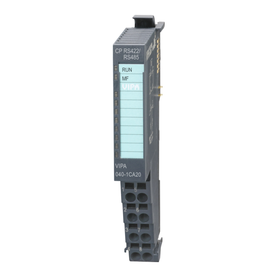
Character delay time ZVZ parameterizable in ms steps Configured by parameter data Order data Type Order number Description CP 040 RS422/485 040-1CA00 Communication processor, RS422/485, isolated, ASCII, STX/ETX, 3964(R), Modbus master/slave short/long HB300 | CP | 040-1CA00 | en | 18-28... -
Page 34: Structure
VIPA System SLIO Hardware description Structure 3.2 Structure Locking lever terminal module Labeling strip Backplane bus LED status indication DC 24V power section supply Electronic module Terminal module Locking lever electronic module Terminal Status indication Description green Bus communication is OK Module status is OK Bus communication is OK Module status reports an error... - Page 35 VIPA System SLIO Hardware description Structure Terminal For wires with a core cross-section of 0.08mm up to 1.5mm Pos. Function Type Description TxD-P (B) Send data (RS422) RxD-P (B) Receive data (RS422) TxD/RxD-P (B) Send-/Receive data (RS485) Request to send (RS485) RTS at logic "1": CP ready to send RTS at logic "0": CP is not sending TERM...
- Page 36 VIPA System SLIO Hardware description Structure RS485 connection RS422 connection *) A bridge between the two TERM inputs activates a terminal resistance of 120Ω on the receiver side between RxD-P (Pin 2) and RxD-N (Pin 6). HB300 | CP | 040-1CA00 | en | 18-28...
- Page 37 VIPA System SLIO Hardware description Structure Defined static voltage For a connection with minimum reflections and the wire-break recognition at RS422/485 levels by parameters operation, the lines may be preset with defined static voltage levels. At the CP interface the wiring of the receiver is realized as follows: Parameter Description Wiring of the receiver...
-
Page 38: Technical Data
VIPA System SLIO Hardware description Technical data 3.3 Technical data Order no. 040-1CA00 Type CP 040 RS422/485 Module ID 0E41 1700 Current consumption/power loss Current consumption from backplane bus 125 mA Current consumption from load voltage L+ (without load) 10 mA... -
Page 39: Technical Data Protocols
VIPA System SLIO Hardware description Technical data > Technical data protocols Order no. 040-1CA00 Datasizes Input bytes 8 / 20 / 60 Output bytes 8 / 20 / 60 Parameter bytes Diagnostic bytes Housing Material PPE / PPE GF10 Mounting Profile rail 35 mm Mechanical data Dimensions (WxHxD) - Page 40 VIPA System SLIO Hardware description Technical data > Technical data protocols Character delay time TMO 0 ... 65535 in ms steps (with 0 triple character time is used) Flow control none, hardware, XON/XOFF Number of telegrams to buffer max. 250 End recognition of a telegram by parameterized end character Number of start characters...
-
Page 41: Deployment
VIPA System SLIO Deployment Fast introduction Deployment 4.1 Fast introduction Overview The communication processor 040-1CA00 enables the serial process connection to dif- ferent destination or source systems. Here the CP is used as peripheral module and power supplied by the back plane bus. Parameter For the parameterization you may send parameter data to the CP that are differently assigned depending on the chosen protocol. -
Page 42: In-/Output Area
VIPA System SLIO Deployment In-/Output area 4.2 In-/Output area Overview Depending on the host system the CP uses for each input and output the following number of bytes in the address area. PROFIBUS: 8byte, 20byte or 60byte selectable PROFINET: 20byte or 60byte selectable CANopen: 8byte EtherCAT: 60byte DeviceNET: 60byte... -
Page 43: Principal Communication Via Back Plane Bus
VIPA System SLIO Deployment Principal communication via back plane bus > Sending data CP_OUT_x The content of these data depends on the structure of data in the send buffer. For more information, see the following pages. 4.3 Principal communication via back plane bus 4.3.1 Sending data When sending from the host, the output data are entered in the output area and by means of the Control-Byte transferred to the CP. - Page 44 VIPA System SLIO Deployment Principal communication via back plane bus > Sending data Acknowledgement Status Bit 3...0 Reserved for receipt Bit 7...4 8h: Acknowledgement: Idle state Ah: Acknowledgement: Data received without fragmentation Ch: Status: Reset was executed on the CP Dh: Status: The entered length is not valid Eh: Status: Error in CP communication –...
- Page 45 VIPA System SLIO Deployment Principal communication via back plane bus > Sending data Length Length of user data for serial communication in byte. User data Enter here the user data for the serial communication. Acknowledgement Status Bit 3...0 Reserved for receipt Bit 7...4 8h: Acknowledgement: Idle state 9h: Acknowledgement: Fragmented transfer started...
-
Page 46: Receiving Data
VIPA System SLIO Deployment Principal communication via back plane bus > Receiving data Host system Byte Function Byte Function Acknowledgement / Status with n = number of used bytes in the address area (IO-Size) Control-Byte Bit 3...0 8h: Idle state - no data available Ah: Transfer last fragment Bh: Execute a reset on the CP Bit 7...4... - Page 47 VIPA System SLIO Deployment Principal communication via back plane bus > Receiving data Host system Byte Function Byte Function 8...n-1 User data Acknowledgement with n = number of used bytes in the address area (IO-Size) Info-Byte Bit 3...0 8h: Idle state - no data available 9h: Data are transferred with fragmentation Ah: Data are transferred without fragmentation Bit 7...4...
- Page 48 VIPA System SLIO Deployment Principal communication via back plane bus > Receiving data Principle of communica- Host system tion with fragmentation Byte Function Byte Function Info-Byte Telegram-Info-Byte Length high byte Length low byte Offset high byte Offset low byte 6...n-1 User data with n = number of used bytes in the address area (IO-Size) After the data are processed in the host system, you have to send an acknowledge to the...
-
Page 49: Examples
VIPA System SLIO Deployment Principal communication via back plane bus > Examples Offset If the Telegram-Info-Byte is 04h, an additional offset is entered. Otherwise there is no Offset in the telegram. Calculating the Offset with fragmented transfer: Data_Offset = (Fragment_counter + 1) × (IO_Size-1) -7 + Offset Data_Offset: –... - Page 50 VIPA System SLIO Deployment Principal communication via back plane bus > Examples Header Host system Byte Function Byte Function 4...15 User data byte 0...11 90h Acknowledgement 1. Fragment Host system Byte Function Byte Function 00h Fragment 1...15 User data byte 12...26 00h Acknowledgement 2.
- Page 51 VIPA System SLIO Deployment Principal communication via back plane bus > Examples Host system Byte Function Byte Function 2Ah Length low byte + 2byte 00h Return Value high byte 00h Return Value low byte 6...45 User data byte 0...39 46...59 is not used A0h Acknowledgement Receive data with frag-...
-
Page 52: Communication Via Handling Blocks
VIPA System SLIO Deployment Communication via handling blocks > Overview Last fragment Host system Byte Function Byte Function 0Ah Fragment-Info 1...15 User data byte 25...39 A0h Acknowledgement 4.4 Communication via handling blocks Communication For the processing of the connecting jobs at PLC side a user program is necessary in the CPU. -
Page 53: Vipa Lib
VIPA System SLIO Deployment Communication via handling blocks > VIPA Lib The data blocks must be assembled in the CPU. Since the data exchange via the backplane bus runs asynchronously, a software handshake is used between the CP and the CPU. For this, both handling blocks have the common CONTROL parameter. -
Page 54: Diagnostic Data
VIPA System SLIO Deployment Diagnostic data 4.5 Diagnostic data Overview Via the parameterization you may activate a diagnostic interrupt for the module. With a diagnostic interrupt the module serves for diagnostic data for diagnostic interrupt incoming As soon as the reason for releasing a diagnostic interrupt is no longer present, the diag- nostic interrupt automatically takes place. - Page 55 VIPA System SLIO Deployment Diagnostic data MODTYP Modul informa- Byte Bit 7 ... 0 tion Bit 3 ... 0: Module class – 1100b: CP Bit 4: set at channel information present Bit 7 ... 5: reserved ERR_D Diagnostic Byte Bit 7 ... 0 Bit 2 ...
- Page 56 VIPA System SLIO Deployment Diagnostic data DIAG_US µs ticker Byte Bit 7 ... 0 0...3 Value of the µs ticker at the moment of the diagnostic µs ticker In the SLIO module there is a timer (µs ticker). With PowerON the timer starts counting with 0.
-
Page 57: Serial Communication Protocols
VIPA System SLIO Serial communication protocols Overview Serial communication protocols 5.1 Overview Serial transfer of a char- The simplest type of information exchange between two stations is the point-to-point link. acter Here the CP serves for the interface between a host system and a communication partner. -
Page 58: Ascii
VIPA System SLIO Serial communication protocols ASCII > Parameter data of ASCII 5.2 ASCII 5.2.1 Basics ASCII Mode of operation ASCII data communication is a simple kind of data exchange that may be compared to a multicast/broadcast function. Individual telegrams are separated by means of character delay time (ZVZ). - Page 59 VIPA System SLIO Serial communication protocols ASCII > Parameter data of ASCII DIAG_EN: Diagnostic Here you activate respectively deactivate the diagnostic function. interrupt Byte Bit 7 ... 0 Range of values: – 00h: deactivate – 40h: activate Default: 00h BAUD: Transfer rate Speed of the data transfer in bit/s (baud).
- Page 60 VIPA System SLIO Serial communication protocols ASCII > Parameter data of ASCII OPTION3: Character frame Byte Bit 7 ... 0 Bit 1, 0: Data bits – 00b = 5 Data bits – 01b = 6 Data bits – 10b = 7 Data bits –...
- Page 61 VIPA System SLIO Serial communication protocols ASCII > Parameter data of ASCII When the ZVZ=0 the character delay time (ZVZ) will be calculated automatically (about double character time). Option6: ZVZ (High byte) Option7: ZVZ (Low byte) Range of values: 0 ... 65535 Default: 250 OPTION8: Number of Defines the number of receive buffers.
- Page 62 VIPA System SLIO Serial communication protocols ASCII > Parameter data of ASCII Parameters Description Wiring of the receiver Signal R(A) 5V (Break evaluation) Signal R(B) 0V With this pre-assignment break detection is with RS422 possible at full-duplex operation. Signal R(A) 0V Signal R(B) 5V This pre-assignment corresponds to the idle state (no sender is activated) at half-duplex operation with RS485.
-
Page 63: Stx/Etx
VIPA System SLIO Serial communication protocols STX/ETX > Parameter data of STX/ETX 5.3 STX/ETX 5.3.1 Basics STX/ETX Mode of operation STX/ETX is a simple protocol employing header and trailer. The STX/ETX procedure is suitable for the transfer of ASCII characters (20h…7Fh). It does not use block checks. Any data transferred from the periphery must be preceded by an STX (Start of Text) fol- lowed by the data characters. - Page 64 VIPA System SLIO Serial communication protocols STX/ETX > Parameter data of STX/ETX Name Bytes Function Default OPTION14 reserved 3110h OPTION15 Operating mode 3111h OPTION16 Line assignment 3112h 1) This record set may only be transferred at STOP state. 2) Value depends on the host system. DIAG_EN: Diagnostic Here you activate respectively deactivate the diagnostic function.
- Page 65 VIPA System SLIO Serial communication protocols STX/ETX > Parameter data of STX/ETX OPTION3: Character frame Byte Bit 7 ... 0 Bit 1, 0: Data bits – 00b = 5 Data bits – 01b = 6 Data bits – 10b = 7 Data bits –...
- Page 66 VIPA System SLIO Serial communication protocols STX/ETX > Parameter data of STX/ETX Option7: TMO (Low-Byte) Range of values: 0 ... 65535 Default: 250 OPTION8: Number start You may select 1 or 2 start identifications. When you select "1" as number of start identifi- identifications cations, the contents of the 2.
- Page 67 VIPA System SLIO Serial communication protocols STX/ETX > Parameter data of STX/ETX 00h: half-duplex 01h: full-duplex Default: 00h OPTION16: Line assign- For a connection with minimum reflections and the break evaluation at RS422/485 opera- ment tion, the lines may be preset with defined static voltage levels. At the CP interface the wiring of the receiver is realized as follows: Parameters Description...
-
Page 68: 3964(R)
VIPA System SLIO Serial communication protocols 3964(R) > Basics 3964(R) 5.4 3964(R) 5.4.1 Basics 3964(R) Mode of operation The 3964(R) procedure controls the data transfer of a point-to-point link between the CP and a communication partner. The procedure adds control characters to the telegram data during data transfer. -
Page 69: Parameter Data Of 3964(R)
VIPA System SLIO Serial communication protocols 3964(R) > Parameter data of 3964(R) Block check character 3964R appends a Block check character to safeguard the transmitted data. The BCC- (BCC-Byte) Byte is calculated by means of an XOR function over the entire data of the telegram, including the DLE/ETX. - Page 70 VIPA System SLIO Serial communication protocols 3964(R) > Parameter data of 3964(R) Name Bytes Function Default OPTION11...14 reserved 310Dh ... 0Eh ... 11h 3110h OPTION15 Operating mode 3111h OPTION16 Line assignment 3112h 1) This record set may only be transferred at STOP state. 2) Value depends on the host system.
- Page 71 VIPA System SLIO Serial communication protocols 3964(R) > Parameter data of 3964(R) OPTION3: Character frame Byte Bit 7 ... 0 Bit 1, 0: Data bits – 00b = 5 Data bits – 01b = 6 Data bits – 10b = 7 Data bits –...
- Page 72 VIPA System SLIO Serial communication protocols 3964(R) > Parameter data of 3964(R) OPTION7: BWZ BWZ is the max. time between acknowledgement of a request telegram (DLE) and STX of the answer telegram. The BWZ is specified in units of 20ms. Range of values: 0 ...
-
Page 73: Modbus
VIPA System SLIO Serial communication protocols Modbus > Basics Modbus OPTION16: Line assign- For a connection with minimum reflections and the break evaluation at RS422/485 opera- ment tion, the lines may be preset with defined static voltage levels. At the CP interface the wiring of the receiver is realized as follows: Parameters Description Wiring of the receiver... -
Page 74: Modbus At The Cp From Vipa
VIPA System SLIO Serial communication protocols Modbus > Parameter data of Modbus Broadcast with slave A request may be addressed to a certain slave or sent as broadcast telegram to all address = 0 slaves. For identifying a broadcast telegram, the slave address 0 is set. Only write com- mands may be sent as broadcast. - Page 75 VIPA System SLIO Serial communication protocols Modbus > Parameter data of Modbus Name Bytes Function Default PII_L 3100h Length process image input data PIQ_L 3101h Length process image output data DIAG_EN 3102h Diagnostic interrupt BAUD Baud rate 3103h PROTOCOL Protocol 3104h OPTION3 Character frame...
- Page 76 VIPA System SLIO Serial communication protocols Modbus > Parameter data of Modbus PROTOCOL Protocol, which is to be used. This setting influences the structure. Range of values with Modbus: 0Ah: Modbus Master ASCII 0Bh: Modbus RTU 0Ch: Modbus Slave ASCII short 0Dh: Modbus Slave RTU short 1Ch:...
- Page 77 VIPA System SLIO Serial communication protocols Modbus > Parameter data of Modbus OPTION5, 6: Delay time Here for the Modbus master a delay time in ms is to be preset. With 0 the delay time is evaluated automatically depending on the protocol with the following formula: Modbus ASCII: with Baudrate in bit/s Modbus RTU:...
- Page 78 VIPA System SLIO Serial communication protocols Modbus > Parameter data of Modbus Parameters Description Wiring of the receiver None (Default) No pre-assignment of the receiving lines. This setting only makes sense with bus-capable special drivers. Signal R(A) 5V (Break evaluation) Signal R(B) 0V With this pre-assignment break detection is with RS422 possible at full-duplex operation.
-
Page 79: Deployment - Modbus
VIPA System SLIO Serial communication protocols Deployment - Modbus > Modbus - Overview 5.6 Deployment - Modbus 5.6.1 Modbus - Overview The number of input and output data, dependent on the IO-Size, is parameterizable via GSD file at the 040-1CA00. For the deployment with Modbus a hardware configuration must always be executed. - Page 80 VIPA System SLIO Serial communication protocols Deployment - Modbus > Modbus - Overview Approach Build-up each for the master and slave side a SLIO system, which both contain a CP 040. Connect both systems via the serial interface. Configure the master section. The configuration of the CP 040 as Modbus master happens via the hardware con- figuration.
-
Page 81: Modbus - Access To Multiple Slaves
VIPA System SLIO Serial communication protocols Deployment - Modbus > Modbus - Access to multiple slaves Configure the slave section. The configuration of the CP 040 as Modbus master happens via the hardware configuration. In addition you need a PLC user applica- tion for the communication with the following structure: OB 100: One-time call of the handling blocks FB 60 - SEND and FB 61 - RECEIVE (or FB 65 SEND_RECV) with all parameters and set R for initialization. -
Page 82: Modbus - Function Codes
VIPA System SLIO Serial communication protocols Deployment - Modbus > Modbus - Function codes Evaluate respond telegram 3. slave: A request may be sent to a specified slave or as broadcast telegram to all slaves. To mark a broadcast telegram the slave address is set to 0. Only write commands may be sent as broadcast. - Page 83 VIPA System SLIO Serial communication protocols Deployment - Modbus > Modbus - Function codes A description of the function codes follows below. Overview With the following Modbus function codes a Modbus master can access a Modbus slave: With the following Modbus function codes a Modbus master can access a Modbus slave. The description always takes place from the point of view of the master: Code Command...
- Page 84 VIPA System SLIO Serial communication protocols Deployment - Modbus > Modbus - Function codes Respond of the slave If the slave announces an error, the function code is send back with an "OR" 80h. Without an error, the function code is sent back. ®...
- Page 85 VIPA System SLIO Serial communication protocols Deployment - Modbus > Modbus - Function codes Respond telegram Slave address Function code Number of Data 1. word Data 2. word Check sum read bytes CRC/LRC 1byte 1byte 1byte 1word 1word 1word max. 125words Write 1 bit 05h Code 05h: Write 1 bit to master output area 0x A status change is via "Status bit"...
-
Page 86: Modbus - Error Messages
VIPA System SLIO Serial communication protocols Deployment - Modbus > Modbus - Error messages Write n bits 0Fh Code 0Fh: Write n bits to master output area 0x Please regard that the number of bits has additionally to be set in byte. Command telegram Slave Function... - Page 87 VIPA System SLIO Serial communication protocols Deployment - Modbus > Modbus - Error messages The following error messages may occur: ERROR01 NO DATA Error no data No telegram arrived within the specified delay time. ERROR02 D LOST Error data lost No data is available because either the receive buffer is full or an error occurred in the receive section.