
Related Manuals for natus ErgoJust


Summary of Contents for natus ErgoJust
- Page 1 Natus ErgoJust and ErgoJust ICU Cart Installation and Functionality Guide Natus ErgoJust cart Natus ErgoJust ICU cart 019667 Rev 05...
-
Page 3: Publisher's Notice
Natus EU Authorized Representative Natus Manufacturing Limited IDA Business Park Gort, Co.Galway, Ireland Safety and standards conformity The Natus ErgoJust cart meets the following safety standards set by domestic and international regulatory agencies for Medical Electrical Equipment. • UL 60601-1 General Requirements •... - Page 4 ErgoJust and ErgoJust ICU Cart Installation and Functionality Guide Blank page. August 22, 2017...
-
Page 5: Table Of Contents
Tilting the keyboard tray (ErgoJust cart only)..........................2-6 Extending the mouse holder tray (ErgoJust cart only).........................2-6 Mounting the mouse holder for left or right handed mouse operation (ErgoJust cart only) ............2-7 Raising/lowering the monitor or All-in-One computer .......................2-7 Rotating and tilting the monitor or All-in-One computer......................2-8 Transporting the ErgoJust and ErgoJust ICU cart ........................2-8... - Page 6 ErgoJust and ErgoJust ICU Cart Installation and Functionality Guide Positioning the video pole brackets............................. 3-5 Mount the video pole................................... 3-6 Mounting the computer bracket ..............................3-8 Mounting the computer ................................. 3-8 Mounting the ISO or UPS................................3-9 Mounting the Natus Photic Stimulator (option) ........................3-12 Mounting the Natus Amplifier Base Unit...........................
- Page 7 Table of Contents PTZ and HD PTZ video option signal and control cables connections ...................4-27 PTZ and HD PTZ option signal and control cables routings ....................4-28 PTZ and HD PTZ video option power cables connections .......................4-29 PTZ and HD PTZ video option power cables routings ......................4-30 Fixed-zoom video option signal and control cables connections ....................4-31 Fixed-zoom video option signal and control cables routings ....................4-32 Securing the cables with tie wraps.............................4-33...
- Page 8 ErgoJust and ErgoJust ICU Cart Installation and Functionality Guide Blank page. August 22, 2017...
-
Page 9: Introduction
(ISO) or uninterruptible power supply (UPS) and basket(s) for clinical supplies. The ErgoJust ICU cart is ideal for EEG monitoring applications in an Intensive Care Unit (ICU). It offers the same features as the ErgoJust cart but utilizes an All-in-One desktop acquisition computer, ideal for a smaller footprint, touchscreen operation in the ICU. -
Page 10: Using This Manual
Intended use The Natus ErgoJust and Natus ErgoJust ICU cart is an accessory for Natus EEG devices based on the NeuroWorks/SleepWorks platform. It provides a portable workstation that houses all equipment (offered by Natus) needed to conduct a video EEG study for routine testing, long-term monitoring (LTM) and EEG monitoring in an intensive care unit (ICU). -
Page 11: Labels And Symbols
Introduction Labels and symbols The following labels and symbols may be affixed to the Natus ErgoJust cart and/or Natus Neurology Incorporated system components: When applied on device: Attention: Consult Accompanying Documentation. (ISO 7000-0434A) When used in documentation: Caution, Warning or Precaution follows. -
Page 12: Safety Summary
Safety summary Warnings The following is an overview of Warnings pertaining to the Natus ErgoJust and Natus ErgoJust ICU system cart. Additional Warnings and Cautions are located in the various sections of this User guide. Please read and understand the information in this User guide and any accompanying documentation thoroughly before using the Natus ErgoJust and Natus ErgoJust ICU cart system. - Page 13 Do not open the cart tower or base. • Do not attempt to service the cart. • Do not remove safety guards or labels designed to protect or inform of possible hazards. • Only Natus approved installers may service or otherwise modify the cart. August 22, 2017...
-
Page 14: Voltage Requirements
50-60 Hz. ISO or UPS The Natus ErgoJust and Natus ErgoJust ICU cart must be used with a Natus-approved ISO or UPS requirements to provide electrically isolated power to all system devices. Please contact Natus Technical Support for more information. -
Page 15: Compatible Natus Ergojust Cart Accessories
Introduction Compatible Natus ErgoJust cart accessories The following is a list of equipment that may be mounted or installed on the Natus ErgoJust cart. Other equipment compatible with the Natus NeuroWorks/SleepWorks system which are not directly mounted or installed are not listed (including software, devices, accessories and cables). -
Page 16: Compatible Natus Ergojust Icu Cart Accessories
ErgoJust and ErgoJust ICU Cart Installation and Functionality Guide Compatible Natus ErgoJust ICU cart accessories The following is a list of equipment that may be mounted or installed on the Natus ErgoJust ICU cart. Other equipment compatible with the Natus NeuroWorks/SleepWorks system which are not directly mounted or installed are not listed (including software, devices, accessories and cables). -
Page 17: Disposal At End Of Operating Life Instructions
Figure 1: ErgoJust cart maximum weight capacities. Natus ErgoJust ICU cart weight capacities Figure 1 shows the maximum weight limitations for the All-in-One computer holder and work surface. Figure 1: ErgoJust ICU cart maximum weight capacities. August 22, 2017... -
Page 18: Cleaning Recommendations
For this cart, preventative maintenance consists of periodically cleaning and inspecting the exterior of the instrument. It is recommended that all repairs be performed by a qualified Natus Neurology Incorporated service representative only. You have the sole responsibility for any malfunctions resulting from improper maintenance or repair by anyone other than an authorized Natus Neurology Incorporated representative. -
Page 19: General Use
Chapter 2 General Use This chapter shows how to adjust the various components on the Natus ErgoJust and Natus ErgoJust ICU carts. August 22, 2017... -
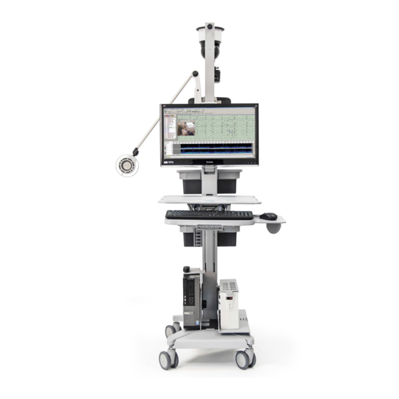
Page 20: Basic Ergojust Cart System Component Identification
ErgoJust and ErgoJust ICU Cart Installation and Functionality Guide Basic ErgoJust cart system component identification Keyboard Mouse Natus Photic Video Camera IR Light and Microphone Stimulator (option) Amplifier Base Unit ISO or UPS Computer Natus Photic Stimulator Video Extension Power Supply... -
Page 21: Basic Ergojust Icu Cart System Component Identification
Mounting the Components Basic ErgoJust ICU cart system component identification Keyboard Mouse ISO or UPS Amplifier Base Unit PTZ or HD PTZ Video Camera, RJ45 to USB Converter, Fixed-Zoom Video Camera, Power Supply, IR Light and Microphone IR Light and Power Supply... -
Page 22: Adjusting The Natus Ergojust And Natus Ergojust Icu Cart Components
Adjusting the Natus ErgoJust and Natus ErgoJust ICU cart components The Natus ErgoJust cart work surface, keyboard and monitor may be adjusted to use in sitting or standing positions. Adjust the height of these components to a comfortable position to minimize strain on the arms, wrists, neck and eyes. -
Page 23: Adjusting The Work Surface Height
Place your hands below the keyboard tray and lift slowly upward to extend the tray to the keyboard tray maximum position (Figure 3). (ErgoJust cart only) Place your hands on top of the keyboard tray and push slowly downward to retract the tray. Figure 3: Extending the ErgoJust cart keyboard tray. August 22, 2017... -
Page 24: Tilting The Keyboard Tray (Ergojust Cart Only)
Figure 4c: Tilt the ErgoJust cart keyboard tray. Extending the mouse You can extend the mouse holder tray to use the mouse on the tray for the ErgoJust cart. holder tray (ErgoJust NOTE: Store the mouse in the mouse holder when not in use or transporting the cart cart only) NOTE: The ErgoJust ICU cart system uses the keyboard with an integrated touchpad mouse. -
Page 25: Mounting The Mouse Holder For Left Or Right Handed Mouse Operation (Ergojust Cart Only)
NOTE: Store the mouse in the mouse holder when not in use and when transporting the cart. Raising/lowering the The ErgoJust cart uses a small-form factor desktop computer and a monitor. The ErgoJust ICU cart monitor or All-in-One features a touchscreen All-in-One (AiO) computer. The AiO computer is mounted on the mast to monitor mount. -
Page 26: Rotating And Tilting The Monitor Or All-In-One Computer
ErgoJust and ErgoJust ICU Cart Installation and Functionality Guide Rotating and tilting the The monitor can be rotated 90 counterclockwise only for portrait or landscape viewing (Figure monitor or All-in-One computer NOTE: Ensure all cables connected to the All-in-One computer have freedom of motion before rotating it. -
Page 27: Ergojust Cart Installation
Chapter 3 ErgoJust Cart Installation This chapter shows how to mount and cable the components on the Natus ErgoJust cart. Review the contents of this chapter before starting any of the procedures. IMPORTANT: All Natus ErgoJust cart systems must be installed or upgraded by a qualified and trained Natus technician or representative. -
Page 28: Mounting The Keyboard
Set the keyboard on the keyboard tray and secure it in place with the provided Velcro strips. Figure 1: Mounting the keyboard. NOTE: The Natus ErgoJust cart is equipped with a height limiter on the mast below the Keyboard tray (Figure 2). This height limiter is designed to guard against the Keyboard tray from coming in contact with the equipment installed on the cart base (providing at least 1 inch clearance). -
Page 29: Removing The Video Pole
ErgoJust Cart System Removing the video pole The ErgoJust video pole may on occasion need to be removed during transportation to fit the cart through an unusually small entryway, access cables inside the video pole, or replace the video pole. - Page 30 ErgoJust and ErgoJust ICU Cart Installation and Functionality Guide IMPORTANT: Do NOT remove the mounting screws in the following step. If the mounting screws are removed, the mounting plate(s) will slide down. Ensure the plates are orientated with the concave side of the plate pointing outward away from the bottom mast when remounting the video pole (Figure 3).
-
Page 31: Mounting The Video Pole
ErgoJust Cart System Mounting the video pole It is recommended to use an assistant when mounting the video pole to avoid injury or damage to the equipment. Positioning the video NOTE: Steps 1 - 4 are required only if the Video Pole mounting screws were removed instead of pole brackets loosened when the Video Pole was removed. -
Page 32: Mount The Video Pole
ErgoJust and ErgoJust ICU Cart Installation and Functionality Guide Mount the video pole IMPORTANT: Press all four screws inwards until they are tight against the Video Pole (Figure 3) when performing the next step. This is necessary to position both brackets properly in order to slide the brackets into both grooves on the bottom mast. - Page 33 ErgoJust Cart System NOTE: Confirm that the Video Pole is seated properly on the lower mast (Figure 5). If it is not seated correctly, the brackets did not slide into the two slots. Remove the Video Pole and repeat step 4 above.
-
Page 34: Mounting The Computer Bracket
ErgoJust and ErgoJust ICU Cart Installation and Functionality Guide Mounting the computer bracket Mount the computer bracket to the bottom of the video pole using the furnished three mounting screws and a 4mm allen wrench (Figure 1). Figure 1. Mounting the computer Loosen the six securing knobs (Figure 1). -
Page 35: Mounting The Iso Or Ups
ErgoJust Cart System Mounting the ISO or UPS Carefully set the ISO or UPS and cage on the cart base and slide the ISO or UPS into the cage (Figure 1). Figure 1. Verify Bracket 1 is positioned properly in Slot 1 (Figure 2). - Page 36 UPS though the cage’s cable cutout. Ensure that the tab on the cage inserts into Slot B after tilting the ISO or UPS fully upright (Figure 4). Figure 4. Feed the Natus Photic Stimulator power cable between the ISO or UPS cage and cart post (Figure 5). Figure 5.
- Page 37 ErgoJust Cart System 8. Slide the cage rear cover into the ISO or UPS main cage (Figure 7). Figure 7: Slide ISO or UPS cage rear cover into place. Secure the rear cover to the ISO or UPS main cage using three screws (Figure 8).
-
Page 38: Mounting The Natus Photic Stimulator (Option)
ErgoJust and ErgoJust ICU Cart Installation and Functionality Guide Mounting the Natus Photic Stimulator (option) Insert the optional Natus Photic Stimulator mounting post into the accessory bar (Figure 1). It may be located on either side of the main post. -
Page 39: Mounting The Ir Light And Microphone
ErgoJust Cart System Mounting the IR light and microphone Unscrew the cable channel mounting knob (Figure 1) and set the cable channel cover aside. Figure 1: Removing the cable channel cover. With an assistant, hold on to the IR Light and Microphone during the next step to guard against dropping the IR Light and Microphone. -
Page 40: Mounting The Video Camera
ErgoJust and ErgoJust ICU Cart Installation and Functionality Guide Mounting the video camera With an assistant, hold on to the Video Camera during the next step to guard against dropping the camera. Install and tighten the four Video Camera mounting screws (Figure 1). -
Page 41: Adjusting The Handle Height
ErgoJust Cart System Adjusting the handle height Bend the middle of the basket (A) slightly away from the handle and swing the bottom of the basket (B) towards yourself until the two basket mounting tabs snap free from the two mounting holes (Figure 1). -
Page 42: Replacing A Basket/Handle
ErgoJust and ErgoJust ICU Cart Installation and Functionality Guide Replacing a basket/handle This procedure replaces a damaged basket and/or handle. It is recommended using an assistant to avoid injury or damage to the equipment when removing the video pole. Remove the video pole Remove the video pole (see page 3-3) and then return to step 2 below. -
Page 43: Replacing A Damaged Handle
ErgoJust Cart System Replacing a damaged NOTE: If the handle requires replacement, continue with Replacing a damaged handle on this handle page. If the handle is not damaged, go to Installing the new basket on the next page. a. Loosen the four handle screws and slide the handle up and out from the bottom mast (Figure a). -
Page 44: Install The New Basket
ErgoJust and ErgoJust ICU Cart Installation and Functionality Guide Install the new basket Insert the mounting tab on the right side of the basket into the mounting hole on the handle and then push up on the left side of the basket (Figure 4). -
Page 45: Reinstall The Video Pole Mounting Brackets
ErgoJust Cart System Reinstall the video pole mounting It is recommended to use an assistant when mounting the video pole to brackets avoid injury or damage to the equipment. Improper positioning of the two mounting brackets will allow the Video Pole to separate from the bottom mast, which may damage system components or cause an injury. - Page 46 ErgoJust and ErgoJust ICU Cart Installation and Functionality Guide IMPORTANT: Press all four screws inwards until they are tight against the Video Pole (Figure 9) when performing the next step. This is necessary to position both brackets properly in order to slide the brackets into both grooves on the bottom mast.
-
Page 47: Verifying The Iso Or Ups Voltage
ErgoJust Cart System Verifying the ISO or UPS voltage Your system is configured with the line voltage for the value appropriate to the shipping address. If your system is moved between countries, you may need to guard against possible damage to the electrical components due to improper input voltage. -
Page 48: Removing The Cable Channel Cover
ErgoJust and ErgoJust ICU Cart Installation and Functionality Guide Verify the input voltage printed on the ISO or UPS label is correct for the voltage source that will be used to power the ISO or UPS (Figure 3). Figure 3. -
Page 49: Signal And Control Cables Connections
ErgoJust Cart System Signal and control cables connections See the cable routing diagram on the next page. Figure 1: Cabling the system components. 3-23 August 22, 2017... -
Page 50: Signal And Control Cables Routings
ErgoJust and ErgoJust ICU Cart Installation and Functionality Guide Signal and control cables routings Figure 1: Signal and control cable routings. 3-24 August 22, 2017... -
Page 51: System Power Cables Connections
ErgoJust Cart System System power cables connections Ensure that the ISO or UPS is disconnected (unplugged) from the MAINS power source before connecting power cables to the system components. NOTE: ISO is shown in the example below. See the cable routing diagram on the next page. -
Page 52: System Power Cables Routings
ErgoJust and ErgoJust ICU Cart Installation and Functionality Guide System power cables routings Figure 1: Power cable routings. 3-26 August 22, 2017... -
Page 53: Ergojust Icu Cart Installation
Chapter 4 ErgoJust ICU Cart Installation This chapter shows how to mount and cable the components on the Natus ErgoJust ICU cart. Review the contents of this chapter before starting any of the procedures. IMPORTANT: All Natus ErgoJust ICU cart systems must be installed or upgraded by a qualified and trained Natus technician or representative. -
Page 54: Mounting The Keyboard
Figure 1: Keyboard location. NOTE: The Natus ErgoJust cart is equipped with a height limiter on the mast below the Keyboard tray (Figure 2). This height limiter is designed to guard against the Keyboard tray from coming in contact with the equipment installed on the cart base (providing at least 1 inch clearance). -
Page 55: Removing The Video Pole
ErgoJust ICU Cart System Removing the video pole The video pole may on occasion need to be removed during transportation to fit the cart through an unusually small entryway, access cables inside the video pole, or replace the video pole. - Page 56 ErgoJust and ErgoJust ICU Cart Installation and Functionality Guide 3. Loosen the four video pole mounting screws sufficiently to allow the video pole to be lifted away from the bottom mast (Figure 3). 4. Using an assistant, carefully lift the video pole away from the bottom mast and set it aside (Figure 4).
-
Page 57: Removing The Video Pole Mounted With The Fixed-Zoom Video Camera
ErgoJust ICU Cart System Removing the video Cut and remove the tie wraps shown below (Figure 1). pole mounted with the Fixed-zoom video camera Figure 1: Remove the tie wraps. 2. Unplug the video camera cable (Figure 2). Unplug the video camera and camera control cables. - Page 58 ErgoJust and ErgoJust ICU Cart Installation and Functionality Guide Unplug the Video camera power supply from the ISO/UPS (Figure 3). Carefully remove the Video camera power supply cable from the channel. Figure 3: Unplug the video power supply and remove the video power cable from the channel.
- Page 59 ErgoJust ICU Cart System 6. Loosen the four video pole mounting screws sufficiently to allow the video pole to be lifted away from the bottom mast (Figure 5). 7. Using an assistant, carefully raise the video pole away from the bottom mast and set it aside (Figure 6).
-
Page 60: Mounting The Ergojust Icu Cart Video Pole
ErgoJust and ErgoJust ICU Cart Installation and Functionality Guide Mounting the ErgoJust ICU cart video pole It is recommended to use an assistant when mounting the video pole to avoid injury or damage to the equipment. Positioning the Video NOTE: Steps 1 - 4 are required only if the Video Pole mounting screws were removed instead of Pole brackets loosened when the Video Pole was removed. -
Page 61: Mount The Video Pole
ErgoJust ICU Cart System Mount the video pole IMPORTANT: Press all four screws inwards until they are tight against the Video Pole (Figure 3) when performing the next step. This is necessary to position both brackets properly in order to slide the brackets into both grooves on the bottom mast. - Page 62 ErgoJust and ErgoJust ICU Cart Installation and Functionality Guide NOTE: Confirm that the Video Pole is seated properly on the lower mast (Figure 5). If it is not seated correctly, the brackets did not slide into the two slots. Remove the Video Pole and repeat step 4 above.
-
Page 63: Mounting The Iso Or Ups
ErgoJust ICU Cart System Mounting the ISO or UPS Carefully set the ISO or UPS and cage on the cart base and slide the ISO or UPS into the cage (Figure 1). Figure 1. Verify Bracket 1 is positioned properly in Slot 1 (Figure 2). - Page 64 UPS though the cage’s cable cutout. Ensure that the tab on the cage inserts into Slot B after tilting the ISO or UPS fully upright (Figure 4). Figure 4. Feed the Natus Photic Stimulator power cable between the ISO or UPS cage and cart post (Figure 5). Figure 5.
- Page 65 ErgoJust ICU Cart System 8. Slide the cage rear cover into the ISO or UPS main cage (Figure 7). Figure 7: Slide ISO or UPS cage rear cover into place. Secure the rear cover to the ISO or UPS main cage using three screws (Figure 8).
-
Page 66: Mounting The Amplifier Base Unit
ErgoJust and ErgoJust ICU Cart Installation and Functionality Guide Mounting the amplifier base unit NOTE: Ensure the base unit has a Headbox Side Quick Disconnect Bracket attached. Insert the four mounting pins on the rear of the Amplifier Base Unit into the four mounting holes on the video pole side quick disconnect bracket (Figure 1) and slide the Amplifier Base Unit downward until the locking pin snaps into the quick disconnect bracket locking hole. -
Page 67: Ptz And Hd Ptz Video Option
ErgoJust ICU Cart System PTZ and HD PTZ video option The following two pages describe how to mount the PTZ and HD PTZ video camera and IR light with microphone (Figure 1). Figure 1: PTZ/HD PTZ video camera and IR light with microphone. -
Page 68: Mounting The Ir Light And Microphone
ErgoJust and ErgoJust ICU Cart Installation and Functionality Guide Mounting the IR light Unscrew the cable channel mounting knob (Figure 1) and set the cable channel cover aside. and microphone Figure 1: Removing the cable channel cover. With an assistant, hold on to the IR Light and Microphone during the next step to guard against dropping the IR Light and Microphone. -
Page 69: Fixed-Zoom Video Option
ErgoJust ICU Cart System Fixed-zoom video option The following two pages describe how to mount the Fixed-zoom video camera, IR light and microphone (Figure 1). Figure 1: Fixed-zoom video camera and microphone. Mounting the Unscrew the cable channel mounting knob (Figure 2) and set the cable channel cover aside. -
Page 70: Mounting The Fixed-Zoom Video Camera
ErgoJust and ErgoJust ICU Cart Installation and Functionality Guide Mounting the Fixed- Attach the video camera mount to the video camera (Figure 3). zoom video camera With an assistant, hold on to the video camera during the next step to guard against dropping the camera. -
Page 71: Adjusting The Handle Height
ErgoJust ICU Cart System Adjusting the handle height Bend the middle of the basket (A) slightly away from the handle and swing the bottom of the basket (B) towards yourself until the two basket mounting tabs snap free from the two mounting holes (Figure 1). -
Page 72: Replacing A Basket/Handle
ErgoJust and ErgoJust ICU Cart Installation and Functionality Guide Replacing a basket/handle This procedure replaces a damaged basket and/or handle. It is recommended using an assistant to avoid injury or damage to the equipment when removing the video pole. Remove the video pole Remove the video pole (see page 4-3) and then return to step 2 below. -
Page 73: Replacing A Damaged Handle
ErgoJust ICU Cart System Replacing a damaged NOTE: If the handle requires replacement, continue with Replacing a damaged handle on this handle page. If the handle is not damaged, go to Installing the new basket on the next page. a. Loosen the four handle screws and slide the handle up and out from the bottom mast (Figure a). -
Page 74: Install The New Basket
ErgoJust and ErgoJust ICU Cart Installation and Functionality Guide Install the new basket Insert the mounting tab on the right side of the basket into the mounting hole on the handle and then push up on the left side of the basket (Figure 4). -
Page 75: Reinstall The Video Pole Mounting Brackets
ErgoJust ICU Cart System Reinstall the video pole mounting It is recommended to use an assistant when mounting the video pole to brackets avoid injury or damage to the equipment. Improper positioning of the two mounting brackets will allow the Video Pole to separate from the bottom mast, which may damage system components or cause an injury. - Page 76 ErgoJust and ErgoJust ICU Cart Installation and Functionality Guide IMPORTANT: Press all four screws inwards until they are tight against the Video Pole (Figure 9) when performing the next step. This is necessary to position both brackets properly in order to slide the brackets into both grooves on the bottom mast.
-
Page 77: Verifying The Iso Or Ups Voltage
ErgoJust ICU Cart System Verifying the ISO or UPS voltage Your system is configured with the line voltage for the value appropriate to the shipping address. If your system is moved between countries, you may need to guard against possible damage to the electrical components due to improper input voltage. -
Page 78: Removing The Cable Channel Cover
ErgoJust and ErgoJust ICU Cart Installation and Functionality Guide Removing the cable channel cover The Video Camera, IR Light and Microphone cables feed through the video pole, which may require removing the cable channel cover to access the cables. Unscrew the cable channel mounting knob (Figure 1) and set the cable channel cover aside. -
Page 79: Ptz And Hd Ptz Video Option Signal And Control Cables Connections
ErgoJust ICU Cart System PTZ and HD PTZ video option signal and control cables connections See the PTZ and HD PTZ video option signal and control cable routing diagram on the next page. Figure 1: PTZ and HD PTZ option signal and control cable connections. -
Page 80: Ptz And Hd Ptz Option Signal And Control Cables Routings
ErgoJust and ErgoJust ICU Cart Installation and Functionality Guide PTZ and HD PTZ option signal and control cables routings Figure 1: PTZ and HD PTZ video option signal and control cable routings. 4-28 August 22, 2017... -
Page 81: Ptz And Hd Ptz Video Option Power Cables Connections
ErgoJust ICU Cart System PTZ and HD PTZ video option power cables connections Ensure that the ISO or UPS is disconnected (unplugged) from the MAINS power source before connecting power cables to the system components. See the PTZ and HD PTZ video option power cable routing diagram on the next page. -
Page 82: Ptz And Hd Ptz Video Option Power Cables Routings
ErgoJust and ErgoJust ICU Cart Installation and Functionality Guide PTZ and HD PTZ video option power cables routings Figure 1: PTZ and HD PTZ video option power cable routings. 4-30 August 22, 2017... -
Page 83: Fixed-Zoom Video Option Signal And Control Cables Connections
ErgoJust ICU Cart System Fixed-zoom video option signal and control cables connections See the Fixed-zoom video option cable routing diagram on the next page. Figure 1: Fixed-zoom video option signal and control cable connections. 4-31 August 22, 2017... -
Page 84: Fixed-Zoom Video Option Signal And Control Cables Routings
ErgoJust and ErgoJust ICU Cart Installation and Functionality Guide Fixed-zoom video option signal and control cables routings Figure 1: Fixed-zoom video option signal and control cable routings. 4-32 August 22, 2017... -
Page 85: Securing The Cables With Tie Wraps
ErgoJust ICU Cart System Securing the cables Attach tie wraps to the ErgoJust ICU cart cables as shown below after cabling the system with tie wraps components (Figure 1). Figure 1: Securing the cables with tie wraps. 4-33 August 22, 2017... -
Page 86: Fixed-Zoom Video Option Power Cables Connections
ErgoJust and ErgoJust ICU Cart Installation and Functionality Guide Fixed-zoom video option power cables connections Ensure that the ISO or UPS is disconnected (unplugged) from the MAINS power source before connecting power cables to the system components. See the Fixed-zoom video option cable routing diagram on the next page. -
Page 87: Fixed-Zoom Video Option Power Cables Routings
ErgoJust ICU Cart System Fixed-zoom video option power cables routings Figure 1: Fixed-zoom video option power cable routings. 4-35 August 22, 2017... - Page 88 ErgoJust and ErgoJust ICU Cart Installation and Functionality Guide Blank page. 4-36 August 22, 2017...
- Page 89 ErgoJust cart weight capacities Extending the keyboard tray (ErgoJust cart only) 2-5 ErgoJust ICU cart accessories Extending the mouse holder tray (ErgoJust cart only) 2-6 Locking/unlocking the wheels 2-4 ErgoJust ICU Cart Installation Mounting the mouse holder (ErgoJust cart only) 2-7...
- Page 90 ErgoJust and ErgoJust ICU Cart Installation and Functionality Guide Labels and symbols Manual conventions Mounting Components on a Unibody Mobile Cart 1-1 Natus EU Authorized Representative Patient isolation requirements Preventive maintenance 1-10 PTZ video camera Publisher’s notice Safety and standards conformity...
- Page 92 A Total Service Solution Standing behind every XLTEK product is Natus Medical Incorporated, an internationally respected innovator of medical products and services. Our Neurology systems are backed up by an in-house support team staffed with technical and clinical experts, 24/7 sup- port, remote support via WebEx or VPN, the largest clinical and technical field support network in Neuro/Sleep and cus- tomized service contracts that include preventative maintenance visits and computer upgrades.